Nussbaum ATT BM Series Owner's manual

Page 1 of 54
Technical Instructions
BM Wheel Balancers – new generation from Oct 2010
Status: 27. August 2013

Page 2 of 54

Page 3 of 54
Content:
1. Recommended spare parts list...................................................................................................4
2. General information on servicing machines..............................................................................4
3. Drive belt......................................................................................................................................5
4. Main switch..................................................................................................................................6
5. Motor ............................................................................................................................................8
6. Piezo sensors ..............................................................................................................................9
7. Opto encoder-printed circuit board..........................................................................................10
8. Motor control board...................................................................................................................11
9. Basic board................................................................................................................................13
10. Drive belt pulley.....................................................................................................................16
11. Wheel guard micro switch.....................................................................................................17
12. Potentiometers.......................................................................................................................18
13. Software update basic board ................................................................................................21
14. Software update Touch PC....................................................................................................25
15. Service Functions..................................................................................................................26
16. Mid centring device (NOT QuickSpan) .................................................................................34
17. QuickSpan..............................................................................................................................35
18. Foot pedal (QuickSpan).........................................................................................................36
19. Maintenance unit (QuickSpan)..............................................................................................37
20. Repair Instructions for clamping fingers (QuickSpan)........................................................38
21. Using UNI-LUG and Motorcycle adaptor on QuickSpan......................................................41
22. Trouble shooting and problem solving................................................................................47
23. Electrical schematic layout...................................................................................................51
24. Dimensions ............................................................................................................................53
25. Technical data........................................................................................................................54

Page 4 of 54
1. Recommended spare parts list
A suggested list of spare parts is recommended to be kept at the customer’s location in order to
rectify problems that might occur more quickly. A list below is also provided on our home page.
1987009WH7A POTENTIOMETER Distance + Diameter with cable
1987009WH9A POTENTIOMETER with cable for outside gauge
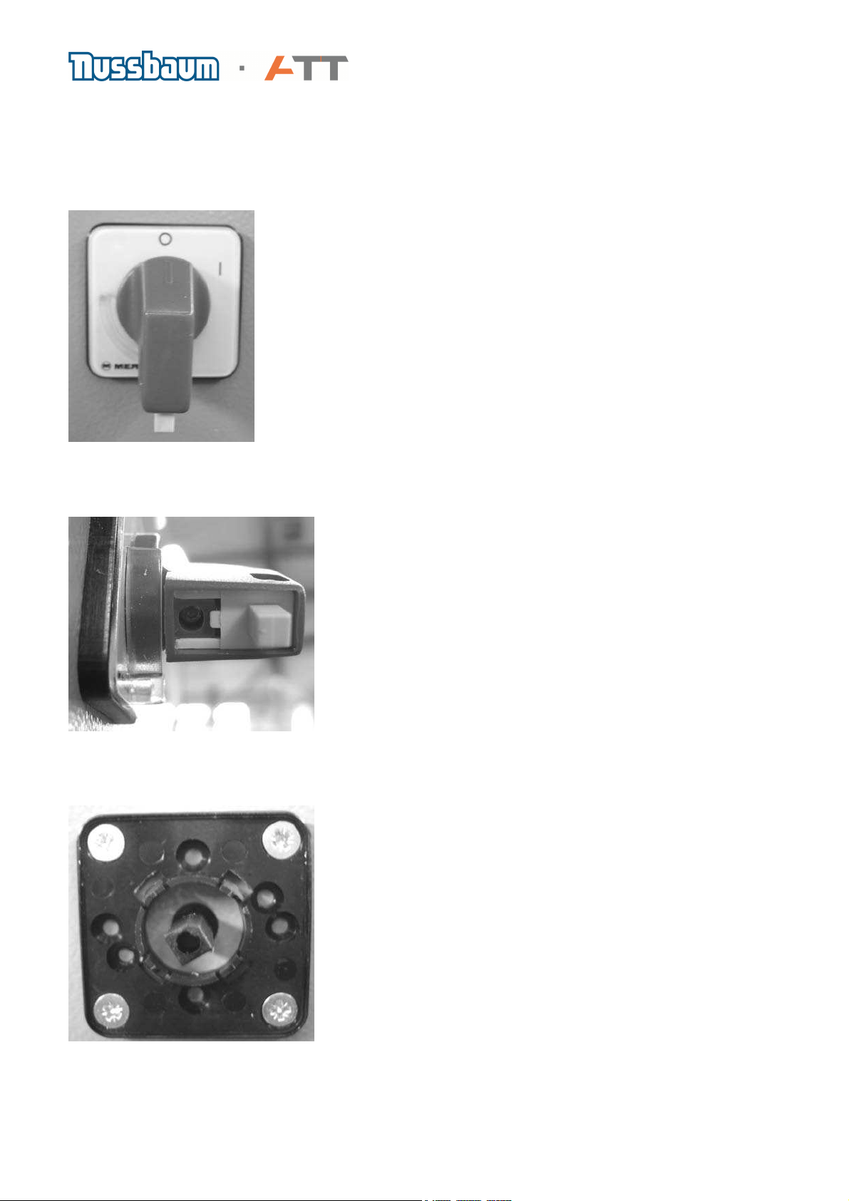
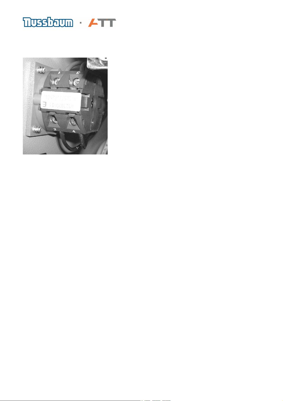
1987009WH4A Wheel guard switch
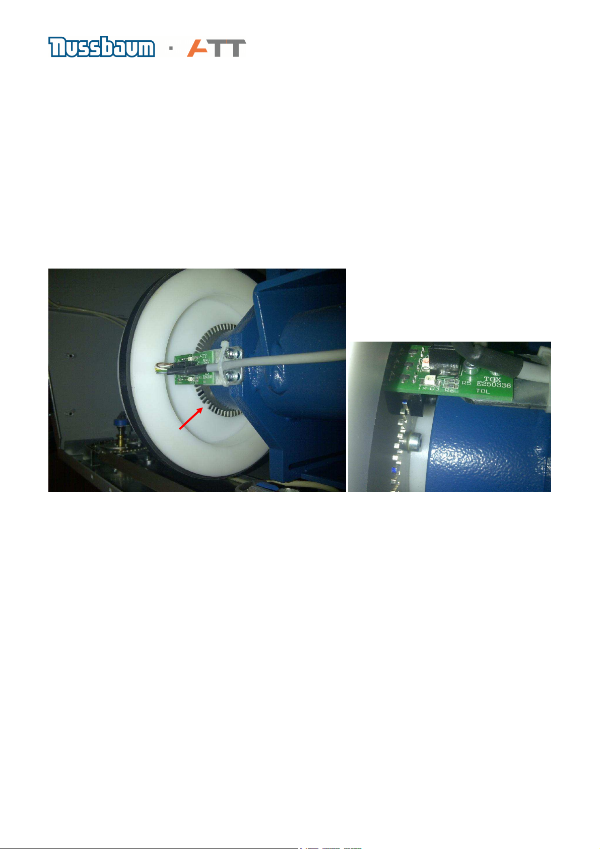
1987009WN3A FORK LIGHT SENSOR with cable
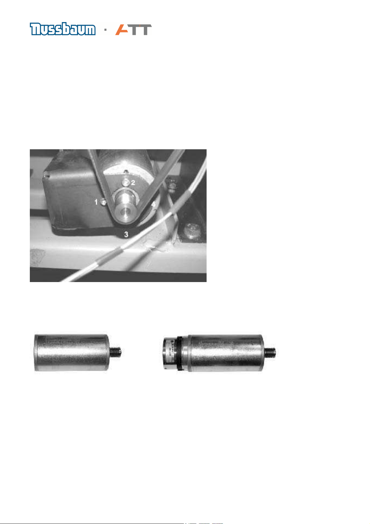
1987009WH2A TRANSDUCER SENSOR complete with cable
1987009WB7A MOTOR with brake
1987009WB5A MOTOR without brake for BM 11, 15 Touch, QuickSpan champ
1987009WD3A PRINTED-BOARD ASSEMBLY for BM 30-2, BM 40-2,
QuickSpan comfort, QuickSpan chrome
1987009WD3A PRINTED-BOARD ASSEMBLY for BM 11, QuickSpan champ
1987009WD2A PRINTED-BOARD ASSEMBLY for Touch PC
1987009WA7A Motor control unit complete for BM 11, 15 Touch
1987009WA8A Motor control unit complete for BM 30-2, 40-2, 35 Touch, 45 Touch,
all QuickSpan models
1987009W8MA Mid centering device QuickSpan complete
1987009W8LA Repair kit QuickSpan „Fingers“
1987009W8NA Repair kit pneumatic cylinder QuickSpan
2. General information on servicing machines
a) Repairs and servicing should only be carried out by qualified personnel.
b) Safety procedures:
Before opening the cover to the electronic parts switch off the main switch and remove the
electrical plug. Take special care not to touch the heat sink on the power control board of the
monitor machine versions because this holds a constant voltage of 230V, or 110V when the
machine is connected to the mains!
Never leave a machine unguarded, which has open electrics parts!
Before a machine is brought back into operation after repairs, ensure that no tools or components
are in contact with the rotating parts of the main shaft.
c) Make sure that a zero run and a calibration has been carried out every time after the machine
has been serviced or adjustments have been made to internal components!
d) Should components fitted to other parts e.g. the electronic boards become defective, do not try
to replace these yourself (except for fuses). If the machine is still in under warranty, the complete
board should be changed. A loss of warranty will occur if any alterations are made to individual
components!

Page 5 of 54
e) Use only original parts to avoid the problems arising from using parts not having the correct
technical specifications or which have no guarantee for this machine. Corresponding spare parts
can be found in the spare parts document as well as finding it on our home page.
3. Drive belt
a) In order to replace the drive belt, loosen four bolts (1- 4). Next, loosen the tension bolt (5) to
allow the motor to pivot towards the belt pulley. Take off the belt. Replace with a new belt being
careful to make sure that the belt is as close as possible to the main shaft assembly to allow it to
fit correctly onto the small drive pulley. Tighten the tension bolt (5) and then the four mounting
bolts (1-4). Make sure that the tension on the belt is sufficient to allow 1cm
b) The direction arrows on the drive belt have no role to play because the rotation of 150 rpm for
the main shaft is very low. Direction arrows can be ignored.
(Drive belt, Art.Nr. 1987009WK1A)
c) Noises coming from the belt do not affect the results on the machine. Do not use grease or oils
to lubricate otherwise the loss of friction on the pulley could alter the rotational speed of the main
shaft.

Page 6 of 54
4. Main switch
a) The main switch can be found on the left side of all machines. It can also be used as an
emergency off switch. Before any repairs are carried out to the machine please do not forget to:
DISCONNECT MAINS PLUG!
b) In order to remove the main switch, loosen the small screw as seen in the picture and pull on
the lever.
From the outside you will now see four screws on the cabinet wall, which secures the main body
of the switch. Loosen these screws to remove the element.

Page 7 of 54
The next picture shows the inside of the cabinet with the main body and two of the four screws.
On the main body are four electrical connections numbered 14 which are the in and out going
power lines to the main switch.
Contact 1 is the outer conductor and contact 3 is the Neutral wire which is connected to an earth
plug. Contact 2 is the inner conductor and is protected by fuse X1-F1. Contact 4 connects to the
neutral connection X1. (If in doubt, please check wiring diagram)

Page 8 of 54
5. Motor
a) Disconnect the red and black motor cable at the point (J2-2, J2-3). In addition if the machine is
a model (above BM30) also disconnect the two grey brake leads at the point (J4-2, X1-3).
b) Loosen the drive belt as described in Para. 5. Loosen the securing screws(1)
(4) to remove the motor. Place new motor in position and tighten the screws (1)-(4).
Replace the drive belt as described above and replace the electrical cables.
c) Note: When ordering new motors make sure that the correct motor for the specific kind of
machine is chosen.
DC motor (24V) without braking capability for BM11, BM 15 Touch and QuickSpan champ and a
DC motor (48V) with braking capabilities for all from BM 30 upwards.
Photo. Shows motor without brakes Photo. Shows motor with brakes
Art.Nr. 1987009WB5A Art.Nr. 1987009WB7A

Page 9 of 54
6. Piezo sensors
a) Disconnect the connecting lead J6 from the Basis board. Loosen the pies sensor securing nut
(1) and screw out the securing bolt (2) using an Allen key. Please note that on machines built from
August 2011 the screw of the sensor is secured inside the thread with Loctite
Look out for the four ball bearings (3) at either end of the piezo sensors. To replace the sensors,
first clean and then put a small dab of grease into the socket spaces for the ball bearings, clen the
thread from remaining Loctite, put medium type Loctite on the screw and place the Piezo sensor
gently into position.
Return each piezo sensor with the ball into position and screw on the sensor securing bolt making
sure that the ball is also in position. Tighten the securing bolt to 2Nm. Do not over tighten the
sensors and tighten the securing bolts alternately.
Replace the securing nut and finally re-connect the leads to the basis board at the point J6.
b) The piezo sensors always come as a set with balls and a single shared lead connecting to a
plug. They can be fitted in any position i.e. front, rear, left or right without any adverse affects on
results. After replacing the sensors, it is imperative that a zero run and calibration are carried out.
Photo shows Piezo sensors (Art.Nr. 1987009WH2A)

Page 10 of 54
7. Opto encoder-printed circuit board
a) There are three red light diodes on the opto encoder printed circuit board. When these three
light diodes are blinking during the operation of the machine, it means the opto encoder is
functioning. If the machine is switched on (CAREFUL VOLTAGE) and the main shaft is turned
slowly, the blinking of the diodes can be observed.
b) To remove, unplug the lead at J2 on the basis board. Loosen the securing screws (1) enabling
the metal support (2) with the opto encoder board to be withdrawn from the machine. Unscrew the
opto encoder board (3) from metal support and replace with another. Return metal support with
opto encoder into position and secure. The opto encoder board must not make any contact with
either the toothed disc (4) or the drive pulley (5). Finally re-connect the plug
c) Note: If a new opto encoder board has been fitted and the position for placing weights cannot
be found, then the actual angle of the opto encoder in relation to the toothed disc should be
checked. As seen in the upper picture, the sensor should be at 90° to the drive pulley
d) If you check the toothed disc, you will find a position where there is a small gap (See red arrow
in the picture above). This position is measured by the opto encoder as Zero point. The toothed
disc has 256 segments and by selecting function F9 on an LED machine you can see the number
of each segment as the main shaft is turned. With monitor machines, the same function can be
checked in the service screen reading from the bottom left of the screen. If the main shaft is
turned a complete revolution in a clock wise direction the scale will count from 0 to 255 and
likewise opposite in a counter clockwise direction.
5
4
3
2
1

Page 11 of 54
8. Motor control board
a) The motor controller board works in conjunction with the transformers (located on the lower
side of the board to make up the power supply for the balance machine. To remove the motor
controller board, unplug the connected cables and loosen the securing screws. Replace a new
board opposite to the method of removing.
b) Overview of the symbols printed next to the relevant connections:
J3 Control line basis board -> Motor controller board
J5 Bridge 115 V / 230 V input voltage
J6 Power supply to the basis board
X5 Mains supply
X4 Connection to primary side of transformer (located below motor control board)
X5 QuickSpan
X6 Connection to secondary side of transformer (located below motor control board)
X7 Motor and Brake
c) The red LED D1 indicates whether 24VDC or 48VDC is available. The LED will stay illuminated
even when the machine has been unplugged from the mains because the power supply unit
contains a filter capacitor. The light can also illuminate when the motor is turned as it acts like a
generator and so charges the capacitor with electricity simultaneously.
More information on fuses see chapter 22
X 7
J
3
J
6
X 1
X 6
X 4
X 5
D 1
J
5
Brake
QuickSpan
Motor
F5
-
Brake
F1
-
Motor
F6
-
QuickSpan

Page 12 of 54
Motor control board lower side
Transformer
Capacitor
AC / DC Bridge

Page 13 of 54
9. Basic board
a) The basic board evaluates and saves all the measurement values and software as well as
controlling the standard electronics. Light diodes can be found on the underside side of the board,
which provides the display for the LED machines. The board is secured to an aluminium plate on
one side and a keypad on the other. On the monitor machine, the basic board is located on the
rear wall of the cabinet to the right side of the PC printed board assembly.
b) To exchange, unplug all leads, remove the board and replace returning the leads to the same
positions.
c) After exchanging a basic board, all measurement values data is lost and so it is important that a
zero run and calibration are carried out.
Generally, the basic board is already flashed with the most up to date software before leaving the
factory, which is why it is very important to note the type and serial number of the machine before
ordering a new board.
d) There are two jumpers plugged into the pins of the connector J12 for the outside gauge as
seen in the photo above, displaying the positions (1-2 and 5-6) they should be in on all machines
except BM 40-2, BM 45 Touch and QuickSpan chrome. From BM40-2 upwards this plug is used
for the outside arm and so the jumpers would have to be removed!
Temperatur
Unused
sensor
Piezo
Sensors
Opto
Encoder

Page 14 of 54
e) The list below shows a summary of all the connectors on the basis board with their codes
which are marked next to each connector on the board.
J1 Key pad (only LED-machines)
J2 Piezo-sensors
J3 unused
J4 unused
J5 Wheel guard micro switch
J6 Opto encoder printed circuit board
J7 unused
J8 Potentiometer for Distance and Diameter
J9 Main power supply coming from Motor controller board.
J10 unused
J11 Temperature sensor
J12 Potentiometer 3 outside arm (from BM40)
J13 Boot-Jumper for Service update of the Software
J32 Foot pedal switch (QuickSpan)
f) When removing the basis board from the aluminium plate, please be careful not to bend the
ribbon cable as it can be easily damaged and cause the machine to function improperly.

Page 15 of 54
On the Touch PC machines the basic board (1) is located inside the machine and mounted on a
panel together with the power pack (2) for the Touch PC
2
1

Page 16 of 54
10. Drive belt pulley
b) To exchange the belt pulley, take off the drive belt and then the screw (3) to enable the pulley
to be taken off the main shaft.
When removing the pulley be careful not to lose the small groove spacer. On fitting a pulley this
small groove spacer has to fit into the groove in the centre of the pulley.
The bolt (3) should then be tightened to exactly 9Nm using a torque wrench. Loctite (medium
type) should also be used to secure the bolt by applying it to the complete length of the threads.
Finally check that the Calibration point (indicator) on the main shaft is in line with the index.

Page 17 of 54
11. Wheel guard micro switch
a) The micro switch relays the position of the wheel guard. Because this process is controlled by
the software, it can be switched off. In this case, any problems arising should first be checked by
noting the functions set by the user with function F8.!
b) To remove, first take out the lead from the connector J5 on the basic board. Loosen the screws
on the switch and remove. Replace the new switch with the wheel guard in an upright position
enabling the contacts J5-1and J5-3 to be connected and in the same case contacts J5-2and j5-3
to be connected with the wheel guard closed.
(Wheel guard micro switch Art.Nr. 1987009WH4A)
c) If the case arises during transport that the camshaft becomes loose as in the photo below, then
re-secure the spring clip by closing the wheel guard so as to align the camshaft with the wheel
guard.

Page 18 of 54
12. Potentiometers
a) Up to three potentiometers can be fitted, depending upon the type of machine.
P1 is the potentiometer at the centre of a chain pulley to measure the distance from the edge of
the machine to the first weight position and depending on the type of program selected, the
second weight position. The potentiometers have a value of 10kOhm/20%/340°.
b) The potentiometers have an internal mechanical stop position, which is important to note when
fitting them to the relevant gauge. The movement of the gauge should not be greater than the
stop position otherwise it could damage the potentiometer. The distance potentiometer is
connected to J8-1to J8-4. In order to remove it, the complete chain pulley and chain should be
removed by loosening the screws securing it to the cabinet wall. When replacing a potentiometer
into the chain pulley, make sure that the potentiometer spindle is turned anti clockwise to almost
the position stop. Thereby, when the chain pulley is fitted together with the potentiometer, they will
be able to both turn clockwise to the chain pulley position stop
The contact no. 1 on the potentiometer take the white coloured wire and no. 2 the green wire, with
no. 3 taking the brown wire.
Contact colour 1 ws 2 gn 3 bn
c) Note: Make sure that while fitting the chain, the gauge is in the home position and the chain
pulley is at the stop position shown by the screwed bolt on the pulley contacting a limit stop. The
potentiometer spindle should also be shortly before the left hand mechanical stop position.

Page 19 of 54
d) The potentiometer measuring the diameter gauge is connected from points J85 to J8-8. When
exchanging please make sure that the potentiometer is turned anticlockwise before fitting.
Important: the end of the gauge should be resting on the top of the main shaft housing during
replacement to allow minimum and maximum measurements to take place for all types of wheel
The contact no. 1 on the potentiometer take the white coloured wire and no. 2 the green wire, with
no. 3 taking the brown wire.
Contact Colour 1 ws 2 gn 3 bn
The photo shows connection plug J8. Connected to it are the leads from Potentiometer P1 for the
distance gauge (right side)and P2 for the wheel diameter (left side from BM 20 upwards) The
colour code order of wires on P2 is black, white, green and brown. For P1 on the other side is also
black, white, green and brown.

Page 20 of 54
e) The potentiometer for the width (outside arm) is connected to J12-1 to J12-4. In order to
exchange the potentiometer these wires should be soldered onto the new one.
The contact no. 1 on the potentiometer take the white coloured wire and no. 2 the green wire, with
no. 3 taking the brown wire.
Contact Colour 1 ws 2 gn 3 bn
The reason why the wires need to be soldered is that the plug for the basic board cannot be
passed through the tube of the wheel guard and so it has to be removed.
The photos show the position of the potentiometers for the outside arm
The left photo shows the plug J12, which takes the leads coming from the outside gauge. On the
right shows the leads, soldered onto the plug in the order brown, green white and black.
Other manuals for ATT BM Series
1
This manual suits for next models
15
Table of contents
Other Nussbaum Wheel Balancer manuals
Popular Wheel Balancer manuals by other brands

Ranger Products
Ranger Products DST-1500 Installation and operation manual

Ravaglioli
Ravaglioli G3.140R instruction manual

Beta
Beta 3070BE/K Instructions for use

John Bean
John Bean VPI System IV Operation instructions

Hofmann
Hofmann Megaspin 800 Operating instructions manual

Cormach
Cormach MEC 5 Techbical Support Manual