Introduction
as a result of regulatory updates or modifications to the
machine.
Any manual upgrades that the manufacturer may see fit to
send to users will become an integral part of the manual
and must be kept together with it.
1.5 COLLABORATION WITH USERS
The manufacturer will be pleased to provide its custom-
ers with any further information they may require and will
consider proposals for improving this manual in order to
more fully satisfy the requirements it was written for.
In case of transfer of ownership of the machine,
which must always be accompanied by the use and
maintenance manual, the original user must inform
the manufacturer of the name and address of the
new user in order to allow it to send the new user
any communications and/or updates deemed to be
indispensable.
This publication is the property of the Manufacturer
and may not be fully or partly reproduced without prior
written agreement.
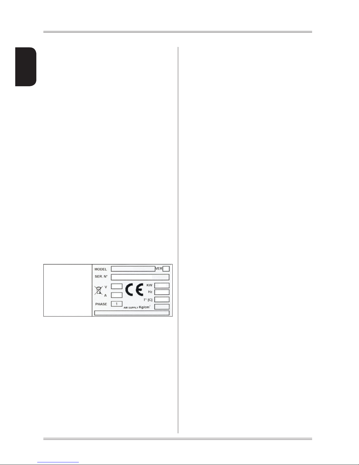
1.6 MANUFACTURER
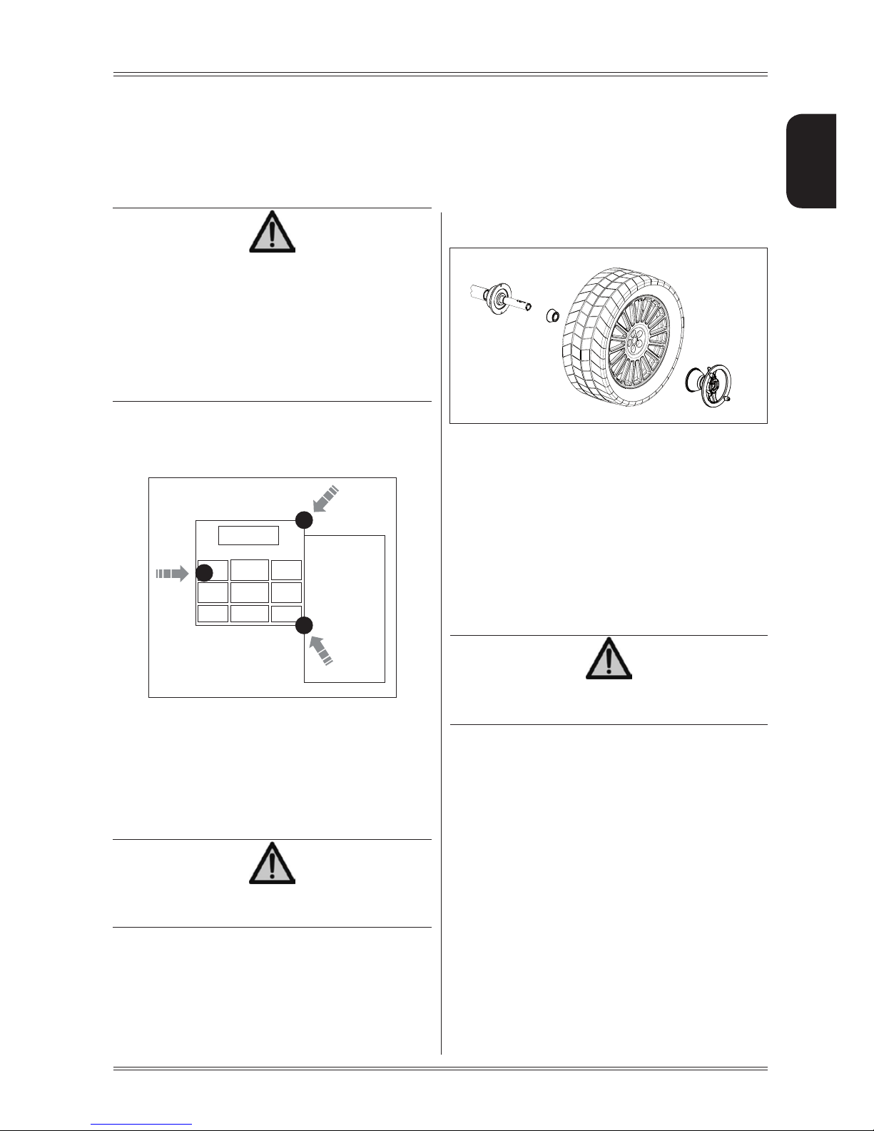
The machine identification data is indicated on the plate
mounted on the machine.
The plate below is shown for the sake of example.
1.7 MANUFACTURER'S RESPONSIBILITY
AND WARRANTY
In order to make use of the manufacturer's warranty, the
user must scrupulously observe the precautions contained
in the manual, in particular he must:
- never exceed the limits of use of the machine;
- always constantly and carefully clean and service the
machine;
- have the machine used by people of proven capacity
and attitude, adequately trained for the purpose.
The manufacturer declines all direct and indirect liability
caused by:
- use of the machine in a different way from that indicated
in this manual
- use of the machine by people who have not read and
fully understood the contents of this manual;
- use in breach of specific regulations in force in the
country of installation;
- modifications made to the machine, software and op-
erating logic, unless authorised by the manufacturer
in writing;
- unauthorised repairs;
- exceptional events.
Transfer of the machine to a third party must also include
this manual; failure to include the manual automatically
invalidates all the rights of the purchaser, including the
terms of warranty, where applicable.
If the machine is transferred to a third party in a country with
a different language from the one written in this manual,
the original user shall provide a faithful translation of this
manual in the language of country in which the machine
will operate.
1.7.1 Terms of warranty
The Manufacturer guarantees the machines it manufac-
turers against all manufacturing or assembly faults for 12
(twelve) months from the date of collection or delivery.
The Manufacturer undertakes to replace or repair any part
which it deems to be faulty free of charge at its factory,
carriage paid.
If a Manufacturer's repairman (or a person authorised by
the same) is required to work at the user's facilities, the
relative travel expenses and board and lodging shall be
charged to the user.
The free supply of parts under warranty is always subject
to the faulty part being inspected by the manufacturer (or
a person authorised by the same).
The warranty is not extended following repairs or other
work done to the machine.
The warranty does not cover damage to the machine
deriving from:
- transport;
- neglect;
- improper use and/or use not in compliance with the
instructions in the operating manual
- incorrect electrical connections.
The warranty is invalidated in case of:
- repairs made by people who were not authorised by
the manufacturer;
- modifications that were not authorised by the manu-
facturer;
- use of parts and/or equipment that were not supplied
or approved by the manufacturer;
- removal or alteration of the machine identification
plate.