Fasep B350.G3 User manual

Fasep 2000 srl Rev. 1.1
Balatron B350.G3 10 September 2012
For any information, please contact: www.fasep.it
e-mail: [email protected]
FASEP 2000 srl
Via Faentina 96
50032 Ronta (Fi) Italy
Tel. #39 055 8403126
Fax #39 055 8403354 i
FIG.1B350.G3.T
BALATRON B350.G3
USER’S MANUAL

Fasep 2000 srl Rev. 1.1
Balatron B350.G3 10 September 2012
ii
WARNING
.This document contains information which is the property of FASEP 2000 srl and all rights are reserved. This manual shall not be
photocopied or reproduced in any way without the prior written consent of FASEP 2000 srl.
.FASEP 2000 srl reserves the right to revise products firmware, software or documentation without obligation to notify any person
or organization. The information contained in this document is subject to change without warning.
.Prior of the installation of the unit described in this manual, user should read this manual carefully to be instructed properly on
installation, use and maintenance of the unit.
.Failing to read this manual and operate accordingly may cause damage to the user or the unit.
.FASEP 2000 srl shall not be responsible for inconvenience, breakdown, accidents due to uncomplete knowledge of this manual
or uncomplete application of raccomendations described in this manual.
.FASP2000srlshallnotberesponsibleforinconvenience,breakdown,accidentsduetounauthorizedmodificationsoftheunit,use
ofnon-originalor unauthorizedaccessories(see Accessories listing in this manual for alistof original accessoriesavailable for this
model).
.FASEP2000srlshallnotberesponsibleforanyinconvenience,breakdown,accidentscauseddirectlyorindirectlybynot
qualified service. Service to any parts by not qualified persons will void warranty and will void any right of the owner of
the unit.
SYMBOLS AND CONVENTIONS
To speed the retrieval of main information and make easy to understand the instructions, this manual uses the following typing
conventions:
<NAME OF THE PUSH BUTTON> Used to indicate name of push-buttons on the control panel.
DISPLAY Used to indicate text or number visible on the displays on the control panel.
☺ADVICES Contain useful advices or solutions, evidence d with respect to the rest of the text.
NOTE Notes contain important information, evidenced to the rest of the text.
WARNING Warning messages appears corresponding to procedures that, if not properly observed,
may lead to loose of data or cause damage to the unit.
!CAUTION Caution messages appears corresponding to procedures that, if not properly observed,
may cause injuries to the user.

Fasep 2000 srl Rev. 1.1
Balatron B350.G3 10 September 2012
iii
ORIGINAL INSTRUCTIONS
TABLE OF CONTENTS
WARNING .......................................................................................... ii
SYMBOLSANDCONVENTIONS ........................................................................ ii
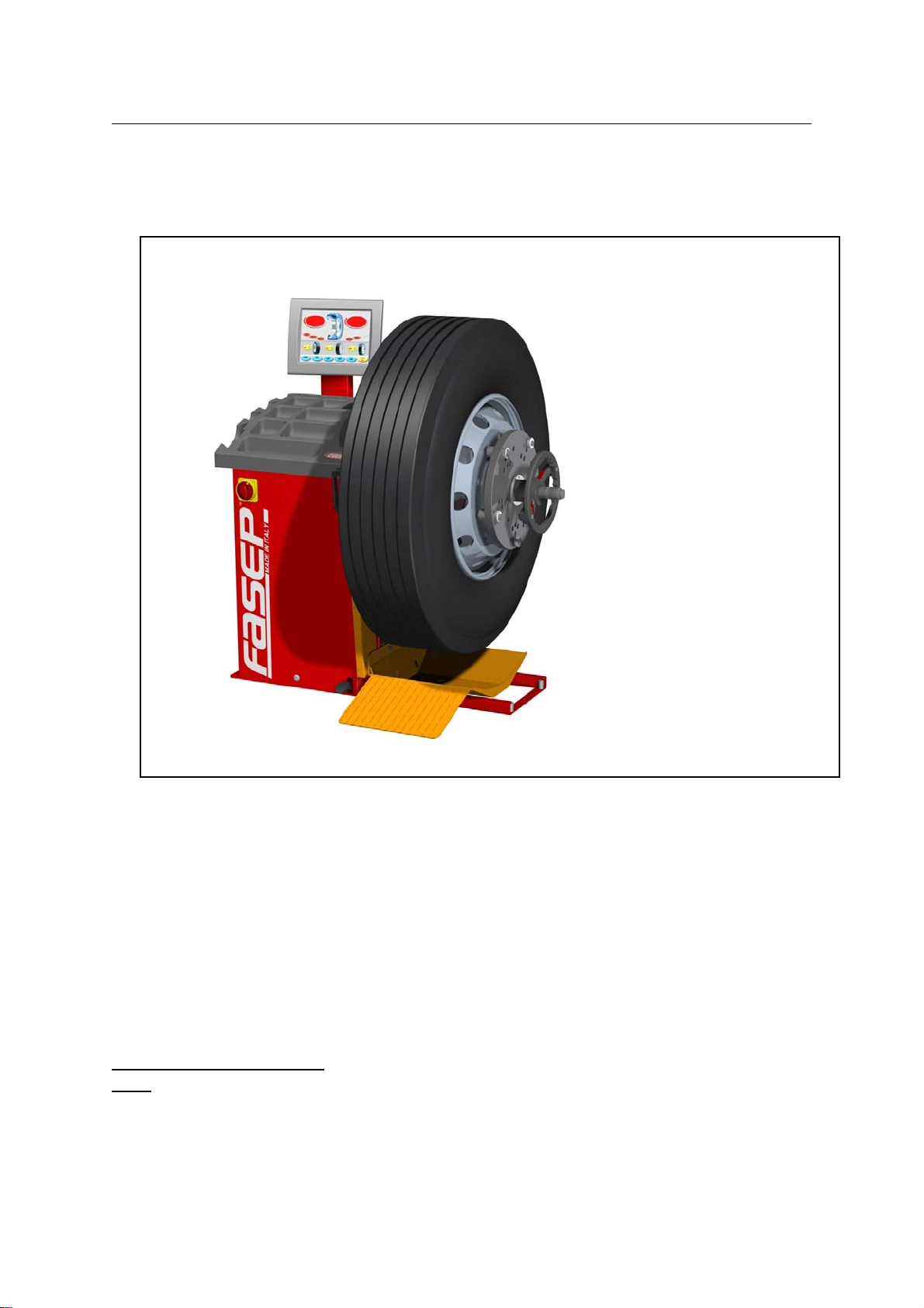
1 PRESENTATION ............................................................................1-1
1.0 Intended Use .......................................................................1-1
1.1 Definitions .........................................................................1-1
1.2 Lifter - Intended Use .................................................................1-2
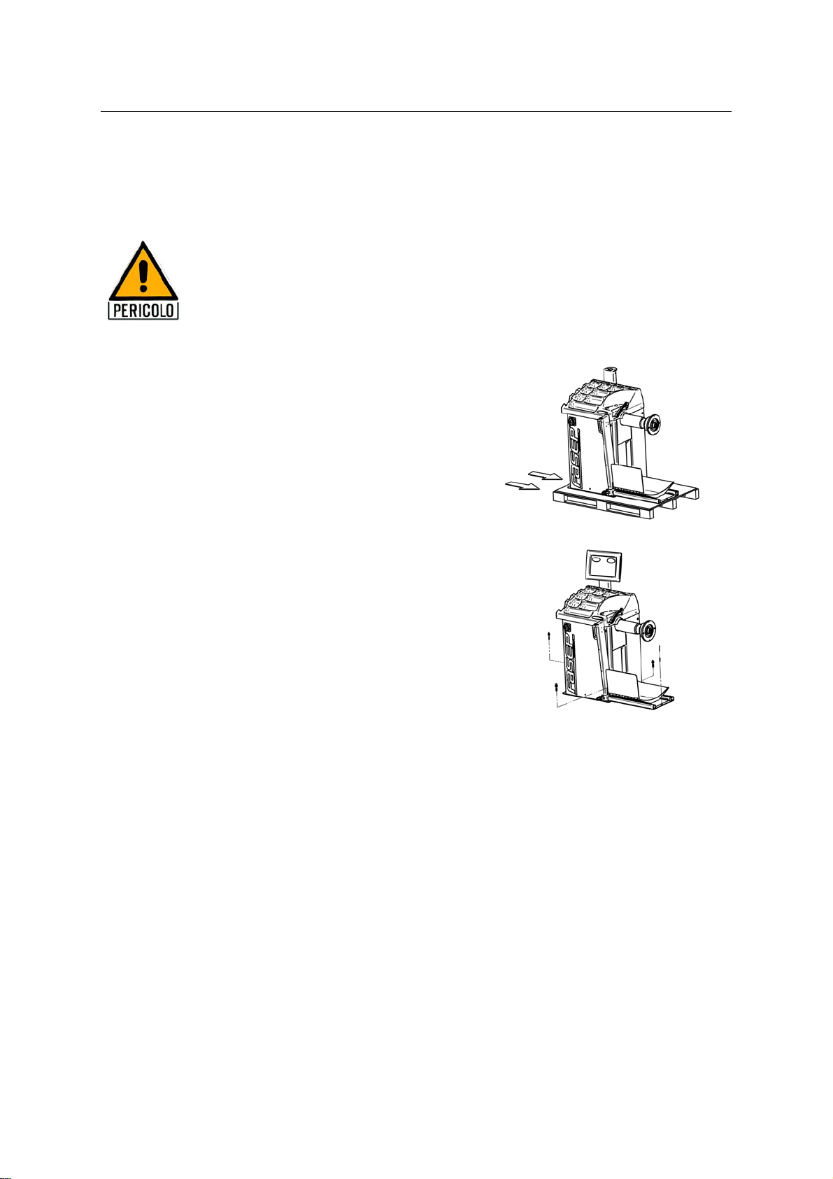
2 INSTALLATION .............................................................................2-2
2.1 Movingtheunit......................................................................2-2
2.2 Assemblingtheunit ..................................................................2-2
2.3 Installation .........................................................................2-2
2.4 ElectricalHookup....................................................................2-2
2.5 Aircompressed .....................................................................2-3
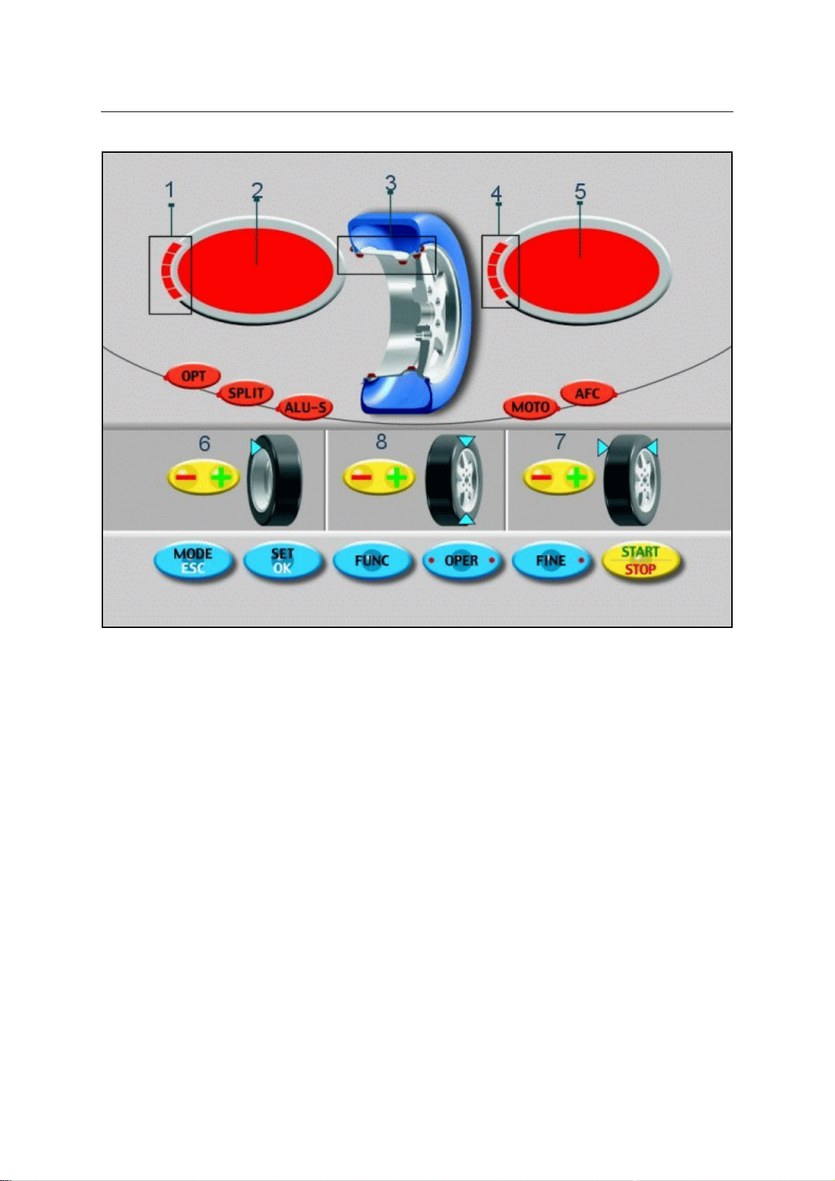
3 USETHECONTROLPANEL ..................................................................3-1
3.1 Meaning of keys at the keyboard ........................................................3-1
3.2 Meaning of Led Indicators .............................................................3-1
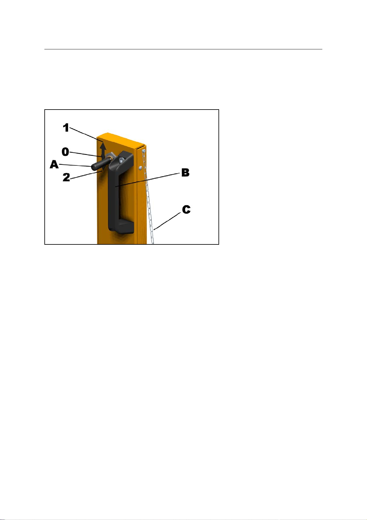
3.3 Useofthelifter......................................................................3-2
4 CALIBRATION ..............................................................................4-1
4.1 How to calibrate the Wheel Balancer B350-T ..............................................4-1
4.2 How to calibrate the Wheel Balancer B350-TC .............................................4-2
4.3 How to control the calibration of Wheel Balancer B350-T .....................................4-3
4.4 How to control the calibration of Wheel Balancer B350-TC ....................................4-4
5 MEASUREMENTANDCORRECTIONOFUMBALANCE ............................................5-1
5.1 Placing the wheel on the wheel balancer ..................................................5-1
5.2 How to compensate umbalance of flanges using AFC function .................................5-1
5.3 Input of Rim Dimensions (trucks) ........................................................5-2
5.4 Detecting and correction of the umbalance ................................................6-1
6 HOWTOOPTIMIZEUMBALANCEOFTHEWHEEL................................................7-1
7 HOW TO USE SPLIT WEIGHT FUNCTION .......................................................8-1
8 SPECIAL FUNCTIONS MENU ..................................................................9-1
8.1 Enterinthespecialfunctionsmenu......................................................9-1
8.2 Diagnostic sensors menu ..............................................................9-1
8.3 Statisticmenu ......................................................................9-1
8.4 UserSetup.........................................................................9-1
APPENDIX ........................................................................................ A-1
A: TechnicalData ............................................................................. A-1
B: Environmental Data, Safety Features and Requirements ............................................ B-2
C: Errors and Malfunctions recognized by the Computer ............................................... C-2

Fasep 2000 srl Rev. 1.1
Balatron B350.G3 10 September 2012
1-1
1 PRESENTATION
1.0 Intended Use
This unit is designed to measure and correct static and dynamic unbalance of vehicle wheel, the dimension and weight
of which are within the working range of the machine (see “Technical Data”appendix for reference).
This unit is meant for a professional use. Operator shall be properly trained before use. Training Course is not included
in the price of the unit and must be purchased separately.
This unit is designed for indoor use only (see “Environmental Data”appendix for reference).
!CAUTION: This unit is designed to spin vehicle wheels only, within the range of dimensions and weight
approved (see “Technical Data”appendix for reference). Special adaptors suit this purpose. Do not
attempt to use the machine to spin anything else. Unproper locking may cause the part being
spinned to be ejected, causing damage to the unit itself, the operator or anything in the in the
neighboorhood.
1.1 Definitions
1. Control Panel
2. Measuring guage
3. Weights compartments
4. Nameplate label
5. Power switch
6. Flange holder
7. Safety chain
8. Pneumatic lifter joystick control
9. Pneumatic lift
10. Sliding wheel support

Fasep 2000 srl Rev. 1.1
Balatron B350.G3 10 September 2012
2-2
1.2 Lifter - Intended Use
Thelifterof this wheel balancer is designed to movewheelof vehicles completewith tire, with size andweightwithintheworkrange
specified (see Appendix 'Technical Data').
This unit is meant for a professional use. Operator shall be properly trained before use, and in any case must carefully read the
“User’s manual”. This unit is designed for indoors use.
- It is expressly forbidden to use the lift to move, raise and lower anything other than a wheel for vehicles.
- After positioning the wheel on the sliding wheel support of the lift, the wheel must be anchored with safety
chain before performing any handling
-Anyotherusethanthosespecifiedshallbedeemedprohibited,notprovidedbythemanufacturerandtherefore
potentially dangerous.
2 INSTALLATION
2.1 Moving the unit
WARNING When the unit has to be moved: never lift
balancer by motor shaft or by neighborhoodof it.
2.2 Assembling the unit
Forease of transportation, the wheelbalancermightbe disassembled
into units. If necessary, assembling instruction are provided within
each package.
2.3 Installation
The wheel balancer must be installed on a firm and level ground.
NOTE: the machine must be secured to the floor. Using four holes
in the base and anchor bolts provided.
2.4 Electrical Hookup
!CAUTION: Failure to follow these instructions can results in
damagetounitor create an electrical hazardand
will void warranty.
2.4.1 Electrical hookup is to be provided by a qualified electrician.
2.4.2 A fusible wall-mounted switchbox is required at the installation site.
This switch should provide on-off control and overload protection for your wheel balancer only. The switchbox should be
fused with time-delay fuse(s) in accordance with the power rating specified on your wheel balancer.
2.4.3 Electrical connection of the machine should be by plug connectors.
2.4.4 The balancer must be effectively connected to ground. The electric cord is regularly provided with a ground terminal.
2.4.5 Make sure that Power Rate Specifications for your wheel balancer (refer to nameplate on the wheel balancer) comply
with those provided by the external power source.
!CAUTION Afterelectricalhookup hasbeenperformedunitisreadytooperate.Always observepertinentsafety
precautions when operating the unit (see Appendix tables for an overview of relevant Safety
requirement).

Fasep 2000 srl Rev. 1.1
Balatron B350.G3 10 September 2012
2-3
2.5 Air compressed
2.5.1 Connect the inlet air to a network of compressed air pressure of 8 -10 bar.
2.5.2 Check that the air supply tube passage has a useful diameter of 6 mm.
!CAUTION LIFTER: Regarding first use of the lift, as the pneumatic circuit probably empty, do not open the
valve control fully. Open the air passage slowly so as to avoid sudden movements of the platform.
Do not enter into the circuit hydraulic oil, brake fluid or other liquids, the circuit is designed
exclusively for the use of compressed air pressure of 8 Bar max

Fasep 2000 srl Rev. 1.1
Balatron B350.G3 10 September 2012
3-1
FIG.6: Panel Balatron 350
3 USE THE CONTROL PANEL
3.1 Meaning of keys at the keyboard
These instructions apply to Normal Operating Mode. Otherfunction maybe activated by these keys in other operating modes (see
Special Functions).
<MODE>: ................................................ Toselectbalancingtype:Dynamic-Static-Alu.
<SET>: ........................................................................ Confirmselection
<OPER>: ........................................................ ToselectOperator1orOperator2.
<FINE>: .................................................................. Toselectreading scale.
<FUNC>: ...............................................................Toselectspecificfunctions
<START-STOP>: ........................................................Starts-stopswheel spinning.
6 <DISTANCE -/+>: ....................................................... Setinternalsidemeasure.
7 <WIDTH -/+>: ............................................................... Setwidthmeasure.
8 <DIAMETER -/+> ......................................................... Setdiametermeasure.
3.2 Meaning of Led Indicators
1-4: ............................................................. indicatelocationofweightrequired.
2-5: ............................................................. indicateamount of weight required.
3: .......................................................... indicatetheapplication point of weights.

Fasep 2000 srl Rev. 1.1
Balatron B350.G3 10 September 2012
3-2
3.3 Use of the lifter
3.3.1 Commands
Lifting \ lowering is controlled by the lever (A) of the valve, located on the lift arm, represented in the figure that has three possible
positions:
1 - Lifting of the wheel
0- Stop (neutral position)
2 - Lowering of the wheel
Note: The lever is held, if issued by the position (1) or (2) automatically returns to the neutral position (0)
Near to the control lever (A) has a handle (B) that allows the operator to move the lift safely.
When the wheel is loaded into the "sliding wheel support", before making any move, the operator must be ensure the wheel in the
arm of the lift by the hook at the bottom of the chain of security (C) in order to avoid tipping from home.
3.3.2 How to use the lift
3.3.2.1 Place the wheel on the sliding wheel support manually.
3.3.2.2 Ensure the wheel firmly to the arm of the lift down by the safety chain
3.3.2.3 Move the control lever into position 1 and to hold it until the axis of rotation of the wheel is at the height of the axis of
rotation of the wheel balancer
3.3.2.4 Release the lever that automatically returnsin to position 0.
3.3.2.5 Hand operated lift arm by sliding on the rails so as to position the wheel near the balancer shaft.
3.3.2.6 If necessary, operate the lever further to correct the position of the wheel in relation to the shaft. Lever (A) in position
1for lifting, lever (A) in position 2for lowering
3.3.2.7 Lock the wheel on the shaft of the balancer.
3.3.2.8 Remove the safety chain from the wheel
3.3.2.9 Lower the sliding wheel support lift and carry it into the machine at rest, making sure that the wheel is free to rotate and
that no part of the lift to interfere with the rotational movement.
3.3.2.10 At the end of the cycle of balancing press the sliding wheel support of the lift to the wheel by operating the valve in
position 1.
3.3.2.11 Replace the safety chain ensuring the wheel on the arm of the lift.
3.3.2.12 Unlock the wheel from the shaft of the balancer.
3.3.2.13 Remove the lift with the wheel on the sliding wheel support from the balancer.
3.3.2.14 Operate the control lever in position 2. The wheel is lowered and can be downloaded manually from the sliding wheel
support by rolling off the ramp
3.3.2.15 The lifter is ready for a new cycle.

Fasep 2000 srl Rev. 1.1
Balatron B350.G3 10 September 2012
4-1
FIG.9
FIG.10
FIG.11
4 CALIBRATION
NOTE: the following symptoms indicate need for calibration:
a) check calibration program fails.
b) constant low or high weight readings.
c) indicated point of umbalance constantly wrong.
d) more than 2 spins required to balance wheels repeatedly.
4.1 How to calibrate the Wheel Balancer B350-T
Switch on the wheel balancer.
Press <SET> when SOF X.XX (software
version) is displayed.
Spin the empty shaft (see the picture 9).
Place the truck flange (see the picture 10).
Put the calibration weight as shown in the
picture 11.
End of calibration.
Press <MODE/ESC> to return to normal balancing mode.

Fasep 2000 srl Rev. 1.1
Balatron B350.G3 10 September 2012
4-2
FIG.13
FIG.14
FIG.15
4.2 How to calibrate the Wheel Balancer B350-TC
Switch on the wheel balancer.
Press <SET> when SOF X.XX (software
version) is displayed.
Spin the empty shaft (see the picture 13).
Place a wheel on the flange (see the picture
14).
Put the calibration weight as shown in the
picture 15.
End of calibration.
Press <MODE/ESC> to return to normal balancing mode.

Fasep 2000 srl Rev. 1.1
Balatron B350.G3 10 September 2012
4-3
FIG.17
FIG.18
4.3 How to control the calibration of Wheel Balancer B350-T
Press <+/-> to select CAL TEST.
Place the truck flange (see picture 17).
Put the calibration weight as shown in the
picture 18.
Press <FINE> to see actual values. 160-0
(±3)
is correct result.
When all LED (left side) are lit, calibration
weight
must be at exactly 6 o’clock.
If no, press <FUNC> to calibrate position.
Turn the flange until the calibration weight is
located at 6 o’clock.
Press <SET> to calibrate the position.
Press <MODE/ESC> to return to normal
balancing mode. FIG.19

Fasep 2000 srl Rev. 1.1
Balatron B350.G3 10 September 2012
4-4
FIG.21
FIG.22
4.4 How to control the calibration of Wheel Balancer B350-TC
Press <+/-> to select CAL TEST.
Place a wheel on the flange (see the picture
21).
Put the calibration weight as shown in the
picture 22.
Press <FINE> to see actual values. 160-0 (±3)
is correct result.
When all LED (left side) are lit, calibration
weight
must be at exactly 6 o’clock.
If no, press <FUNC> to calibrate position.
Turn the wheel until the calibration weight is
located at 6 o’clock.
Press <SET> to calibrate the position.
Press <MODE/ESC> to return to normal balancing mode.
FIG.23

Fasep 2000 srl Rev. 1.1
Balatron B350.G3 10 September 2012
5-1
5 MEASUREMENT AND CORRECTION OF UMBALANCE
5.1 Placing the wheel on the wheel balancer
5.1.1 Select the cone or flange suitable for the wheel to be balanced.
NOTE:the operation of centering and tightening of the wheel on the flanges is of basic importance for correct
balancing. Good results depend on proper performance of these procedures.
Clean accurately all cones, shaft and adappter surface before placing the wheel on the wheel balancer.
!CAUTION: Always make sure flanges are correctly locked on the motor shaft and wheel is correctly locked on
the flange being used.
5.2 How to compensate umbalance of flanges using AFC function
NOTE:This operation allows to put compensate unbalance of flange and other accessories.
5.2.1 Lock the required flange on the shaft without the wheel.
HOW TO TURN ON AFC FUNCTION
The ZERO led blinks.
The ZERO led is on.
HOW TO TURN OFF AFC FUNCTION
Remove the flange.
The ZERO led switch off.

Fasep 2000 srl Rev. 1.1
Balatron B350.G3 10 September 2012
5-2
FIG.26: Posizione Asta per la misura della Distanza FIG.27: Lettura della Distanza
FIG.28: Insert wheel measures
FIG.29: DYNAMIC -STATIC
FIG.30: ALU S-1
FIG.31: ALU S-2
5.3 Input of Rim Dimensions (trucks)
NOTE: DOUBLE OPERATOR option: this wheel balancer can be used from 2 operators in the same time. Everyone
can memorize the dimensions of the wheel to balance with <OPER> buttom. The machine memorizes the
operating procedure too.
5.3.1 (only B350-TC) Press <SET>, press <diam+/-> to set CARS (MOD CAR)or TRUCK (MOD TRU). Press <SET> to
memorize.
Press MODE to select the operating.
Select the diameter.
Select the distance.
Select the width.

Fasep 2000 srl Rev. 1.1
Balatron B350.G3 10 September 2012
6-1
FIG.32: inside weight indication FIG.33: outside weight indication
5.4 Detecting and correction of the umbalance
5.4.1 After setting wheel dimensions, press <START> to spin the wheel and start the measurement run.
5.4.2 At the end of the spin the wheel will brake automatically and the display will show the weight position and weight
requirement to correct the wheel’s umbalance.
5.4.3 If umbalance shown is 0, press <FINE> to show residual umbalance.
NOTE: OPT light blinking after the measurement indicates that static umbalance is exceeding more than 20grs.
Optimization procedure is suggested.

Fasep 2000 srl Rev. 1.1
Balatron B350.G3 10 September 2012
7-1
FIG.35: first spin, rim only
FIG.36: Second spin, complete wheel
6 HOW TO OPTIMIZE UMBALANCE OF THE WHEEL
6.1 Measure the umbalance of the rim only. Once the measurement of rim umbalance is calculated, press <FUNC> to enter
optimization function.
Mount the tyre on the rim. After mounting the
tyre, the wheel must be put on the shaft in the
same position as before.
Left display (20 in example) indicates present
static umbalance. Right display (55% in
example)indicatespossiblereductionofweight
in %.
Turn the wheel until SIGN 1 is displayed.
Mark the rim (12 o’clock).
Turn the wheel until SIGN 2 is displayed.
Mark the tyre (12 o’clock).
Put the two marks together to optimize umbalance.
6.2 After pressing <SET>, the program return to the measurement of umbalance mode, where an indication of the residual
umbalance values will be given.

Fasep 2000 srl Rev. 1.1
Balatron B350.G3 10 September 2012
8-1
7 HOW TO USE SPLIT WEIGHT FUNCTION
7.1 Measure the umbalance of the wheel and press <FUNC> to enter split function.
Turn the wheel until POS 1 is displayed.
Mark the tyre when the first spoke selected is at 12 o’clock.
Turn the wheel until POS 2 is displayed.
Mark the tyre when the second spoke selected is at 12 o’clock.
7.2 The weight in grams for external side is displayed only when the wheel is in a correct position (12 o'clock).

Fasep 2000 srl Rev. 1.1
Balatron B350.G3 10 September 2012
9-1
8 SPECIAL FUNCTIONS MENU
8.1 Enter in the special functions menu
Switch on the wheel balancer and press <SET> before SOF X.XX will disappear.
The possible functions are:
CAL Calibration of wheel balancer
CAL tSt Control of the calibration of electronic sensors
CAL rod Calibration of electronic input sensors
SEn Sor Diagnostic of sensors
StA tiS Statistic about the use of machine
USr Set User setup
tEc Set Technical Setup
Ser nuM Serial number
Act Cod Inserting Activation Codes
8.2 Diagnostic sensors menu
Switch on the wheel balancer and press <SET> before SOF X.XX will disappear. Select Sen Sor and press <SET>
to enter in the diagnostic sensors menu.
The possible functions are:
rPM Balancing speed
dIS Value of distance sensor
dIA Value of diameter sensor
tO Encoder is in the zero position
PoS Angle of position sensor(from 0 to 255)
PS1 Voltage of PS1
PS2 Voltage of PS2
Cou Safety cover is open or closed
8.3 Statistic menu
Switch on the wheel balancer and press <SET> before SOF X.XX will disappear. Select Sta tis and press <SET>
to enter in the statistic menu.
The possible functions are:
tOt Total number of spin
SUC Percent of runs with a good result
da 11 a 17 Percent of wheels with the indicated diameter
CAL Number of calibrations
8.4 User Setup
Switch on the wheel balancer and press <SET> before SOF X.XX will disappear. Select USa SET and press <SET>
to enter in the user setup menu.
The possible functions are:
ScA LE Set 1 or 5 grams step (0.05/0.25 onces)
Cut oFF Set minimum weight to be displayed
Uni Out Unit of measure for the width (0=inch, 1=millimeters)
Uni Umb Unit of measure for the weight (0= grams, 1=once)
Fin AL Display of final (0 = normal, 1 = blink, 2= Go OD).
biP Acustic signal (ON or OFF)
EME StP Motor brakes In case of emergency stop (On or OFF) (OFF: motor power is cut)
Cou Er On = the motor start only if the safety cover is closed;OFF = safety cover is not installed; Aut =
closing of safety cover the motor starts automatically.
rod Enable/Disable automatic input system
rES Et Load Factory Setup

Fasep 2000 srl Rev. 1.1
Balatron B350.G3 10 September 2012
A-1
FIG.38: Wheel balancer dimensions
APPENDIX
A: Technical Data
Power source 3Ph, 50-60Hz, 220-380V
Balancing speed 82-98 rpm
Measuring time 10-25 s.
Measure precision 20grs (B350.G3.T)
Wheel dimensions Rim Diameter da 8" (200mm) a 26" (650mm)
Wheel Diameter max 34" (870mm)
Wheel Weight Max 200 Kg (440Lbs)
Wheel balancer dimensions
B350.G3.T
L (mm) 1170
L1 (mm) 200
L2 (mm) 1530
P (mm) 770
P1 (mm) 300
P2 (mm) 1070
H (mm) 1250
Peso (kg) 170

Fasep 2000 srl Rev. 1.1
Balatron B350.G3 10 September 2012
B-2
Technical Data of the lifters
Maximum wheel weight 140 Kg
Maximum pressure in the system 8 bar
Minimum wheel diameter 700 mm
Maximum wheel diameter 1260 mm
B: Environmental Data, Safety Features and Requirements
Environmental Data
[Operating conditions]
This unit is designed for indoor use only.
Temperature: 0 to 45/C
Relative Humidity: 5 to 80% a 40/
[Storage conditions]
Package is designed for indoor storage only.
Temperature: -25/to 70/C
Relative humidity: 5 at 95% to 40/C
Safety Features
1. The weights compartments may be removed for servicing. It is secured to the machine bodythrough screws so that only
voluntarily it may be removed. Removal of the weights compartments is therefore restricted to Authorized Service
Engineers.
2. TheControl Panelmayberemoved forservicing.Itis secured tothemachinebodythroughscrewssothatonlyvoluntarily
it may be removed. Removal of this protection is therefore restricted to Authorized Service Engineers.
!CAUTION: The safety cover is anyway required when using the motorcycle adapter.
WARNING FASEP 2000 srl shall not be responsible for any inconvenience, breakdown, accidents caused
directlyorindirectlybyunauthorizedservice.Servicetoanypartsbyunauthorizedengineerswillvoid
warranty and will any right of the owner of the unit.
NOTE: As this unit runs at speed below 100rpm, a safety cover is not required. However a safety cover is
recommended when balancing wheels with diameter bigger then 20".
General Safety Requirement
[before using/servicing this unit]
1. Read this instruction sheet and the whole user’s manual before operating or servicing the wheel balancer.
2. Make sure electrical power source conforms to requirements shown on nameplate.
3. Make sure the unit has a stable position and it’s bolted to the ground.
[when using the unit]
4. Protect power leading to the unit from damage.
5. When work area is being washed, make sure unit is adequately protected.
6. Remove all stones and mud lodged in tire treads before balancing the wheel.
7. Do not touch spinning wheel.
8. Make sure counterweights are securely attached before checking residual umbalance.
[when servicing the unit]
9. Make sure power sources are disconnected before service on the unit is performed.
10. Service to PCB, electrical and mechanical parts should be done only by an Authorized FASEP 2000 Service Center.
Lifter Service
1 By its nature, the lift must not be subjected to special attention for maintenance. However, to work better keep clean the
slide rails.
2 Periodically verify that the filter incoming mail to the condensate pneumatic circuit is not full of water, or empty.
- Before performing operations on the mechanisms of the lift with the sliding wheel support in the up position,
placebetweenthefloorandtheslidingwheelsupportitself a pieceof wood that ensuresstabilityinthisposition.
- Not operate on the pneumatic circuit before it was emptied by the internal pressure.
Lifter Safety features
Table of contents
Other Fasep Wheel Balancer manuals

Fasep
Fasep VIDEOTRONIC V548.G4 User manual

Fasep
Fasep VIDEOTRONIC V788.G3 User manual

Fasep
Fasep RGU 56 XL Operation instructions

Fasep
Fasep BALATRON B150 User manual

Fasep
Fasep BALATRON B110 User manual

Fasep
Fasep VIDEOTRONIC V653.G2 User manual

Fasep
Fasep VIDEOTRONIC V644.G3 User manual

Fasep
Fasep B222 User manual

Fasep
Fasep VIDEOTRONIC V688.G3 User manual