Nussbaum ATT BM Series User manual

Page 1 of 15
Quick Installation guide
BM Wheel Balancers – new generation from Oct 2010
Status: 10. December 2013

Page 2 of 15

Page 3 of 15
Content:
1. General.........................................................................................................................................4
2. Assembling the machine ............................................................................................................4
3. Mounting the wheel hood............................................................................................................5
4. Mounting the weight tray and the LE Display............................................................................6
5. Mounting the Touch PC ..............................................................................................................7
6. Putting the machine into operation............................................................................................8
7. Electrical schematic layout.......................................................................................................12
8. Dimensions................................................................................................................................14
9. Technical data............................................................................................................................15

Page 4 of 15
1. General
While selecting the location for the balancer always consider the regulations and instructions of
the Accident Prevention & Insurance Assocation as well as the requirements of the national
working regulations.
The wheel balancer can be located on each flat ground. A fastening of the machine is not
compulsory. For balancing wheels with a weight of more than 40kg, everything is prepared to fix
the machine with dowels on the ground.
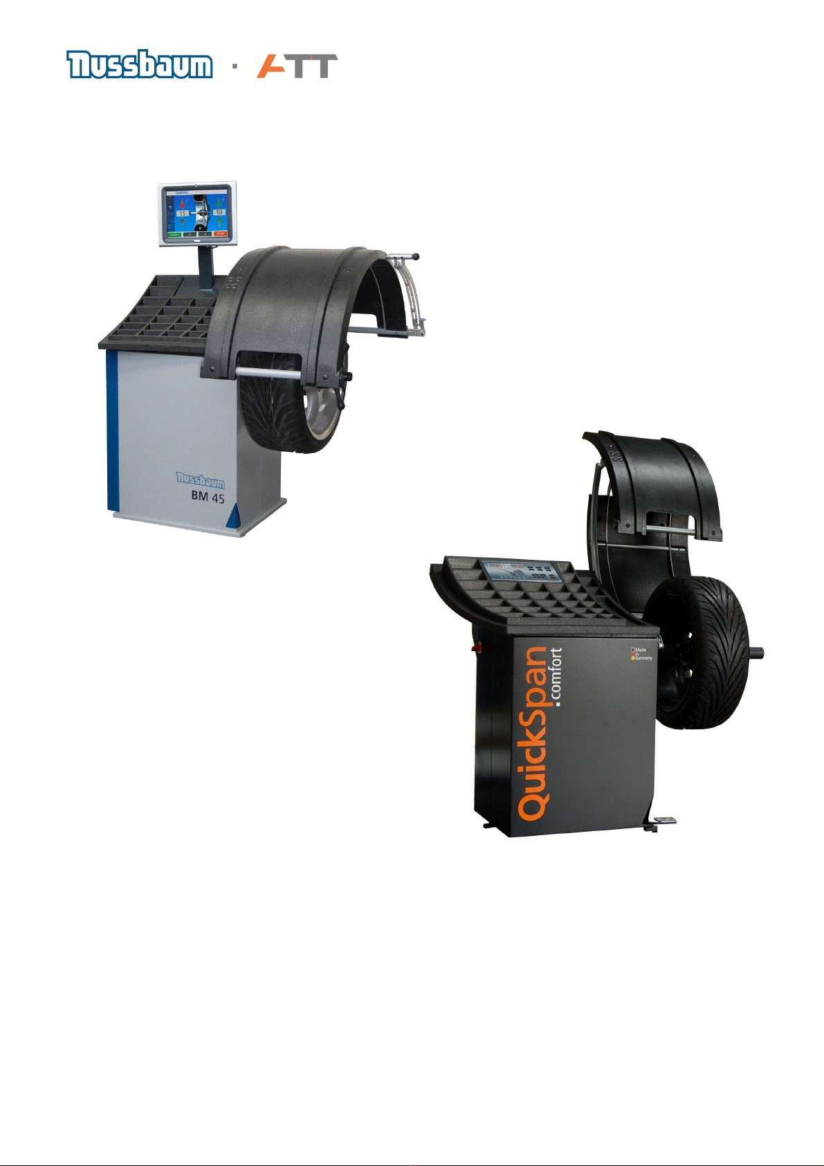
Because of logistical reasons the wheel balancing machines are fragmented in their main
components and packed in special cartons.
The main components are:
- Machine including mid centring device mounted
- Touch PC (for BM x5 – types only)
- Wheel cover/hood
- Weight tray (for BM x5 – types including monitor boom)
- Carton with documentation, Weight pliers, wheel weight removal tool, cones, quick nut (clamping
sleeve for QuickSpan
models), pressure cup for steel wheels, distance ring
2. Assembling the machine
The unpacking, built up and the mounting should be done practically by 2 persons.
After put up and fixing the machine, it has to be positioned on the 3 marked points. If this is not
the case, this has to be compensated with special parts which have to be lay underneath the
marked points (the machine has to be positioned on this points).
Lift up the machine on the pallet and turn it 180° around a corner. Then dump it on the ground.
Pull out the pallet underneath the machine and position the machine smoothly.
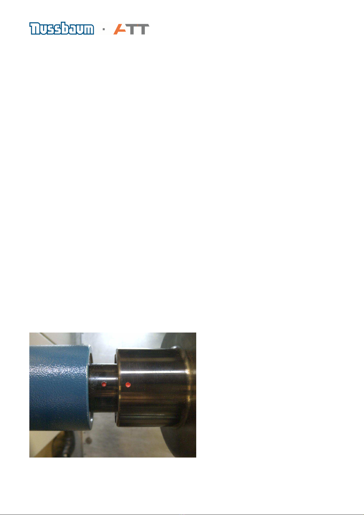
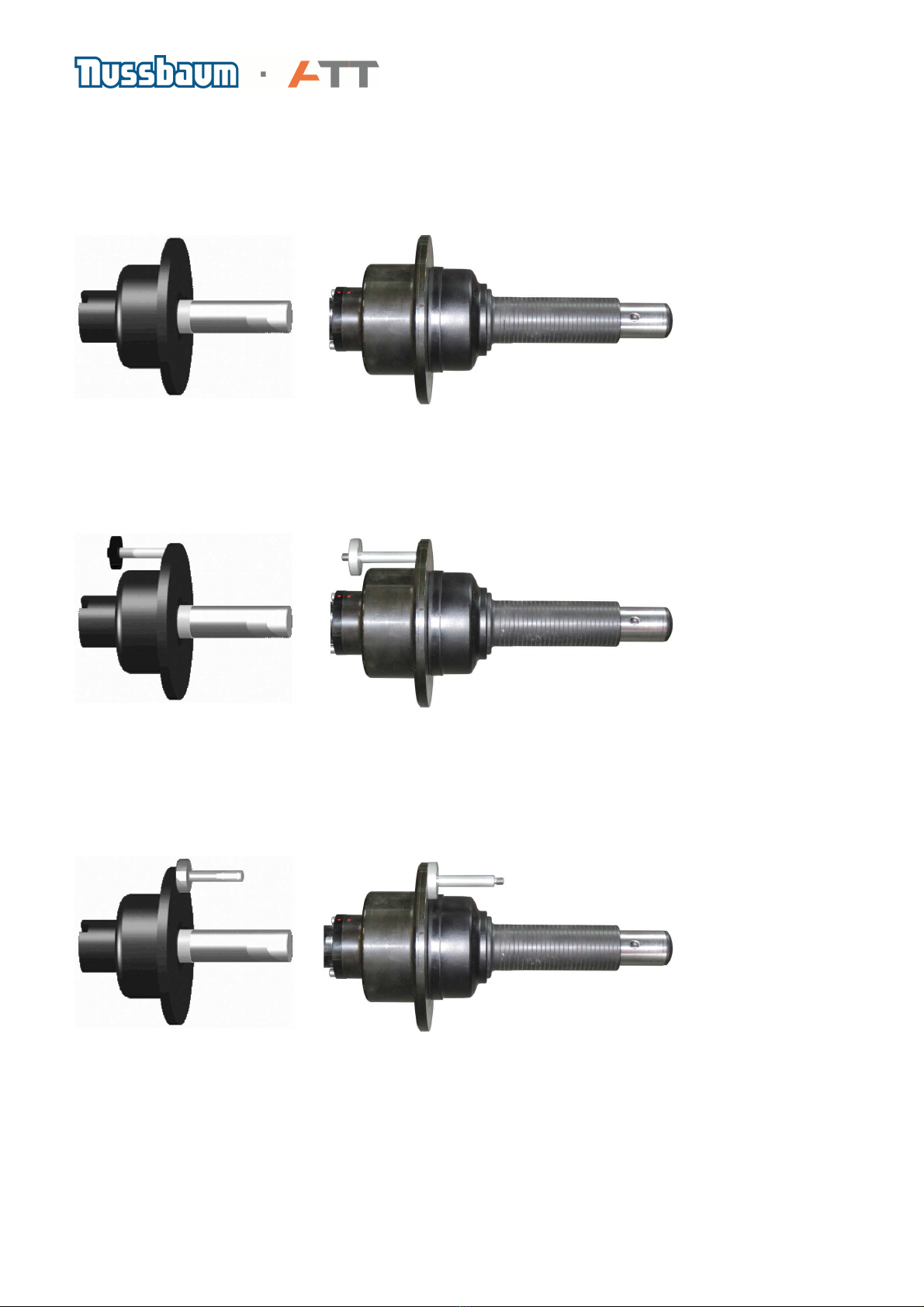
Make sure that the mid centring device is mounted correctly and the 2 red dots (1 on the shaft and
1 on the mid centring device) are in line to each other as shown in the picture below

Page 5 of 15
3. Mounting the wheel hood
The wheel hood is shipped completely assembled including the shaft and wheel hood switch. It is
mounted with 4 screws to the cabinet of the wheel balancer.
The screws are packed in the bag together with the instruction manual.
View from top View from inside of cabinet
The connecting cable of the wheel hood switch has to be routed through the bore holes in the
cabinet and the connection plug has to be connected to J 5 on the display board (see chapter. 4.)
For wheel balancer versions with an outside arm the connecting cable has to be connected to
J 12 as described in the drawing on the display board.

Page 6 of 15
4. Mounting the weight tray and the LE Display
The weight tray is fixed to the cabinet with 4 pieces of duck tape that is already present on the
lower side of the weight tray as well as on the cabinet.
Guide the cables for the LE Display through the hole in the weight tray and mount the weight tray
to the cabinet
The plugs on the cables and the connectors on the display board are marked with numbers which
are also printed on the circuit board. Because of the special form/ design of the connector, it is
guaranteed that they cannot put on in a wrong way.
Temperat
ur
Unused
sensor
Piezo
Sensors
Opto
Encoder

Page 7 of 15
5. Mounting the Touch PC
The basic balancing board where the connectors for the wheel hood switch and for the outside
arm (if present) have to be connected is located inside the cabinet
Guide the serial cable and the power supply cable through the monitor boom and mount the
weight tray to the cabinet
Connect the 2 cables as shown in the picture below
Fix the Touch PC with the screw to the top of the monitor boom

Page 8 of 15
6. Putting the machine into operation
In order to set the machine into operation several general steps are required. The information on
the service functions can also be found in the instruction manual
DIGITAL WHEEL BALANCERS
Via the function key you get into the menu for service functions to select the basic
settings or change them according to the user’s requirements. The various menu functions from
F1 to F14 can be selected by pressing the +- keys
When you are in the function menu, an „Fn“ is shown on the left side of the digital display. The
chosen function is shown on the right side of the digital display.
Once a particular function is desired, it can be chosen by pressing the function key again
Perform the following steps in the order stated below
F 5 Calibration
The calibration weight supplied with the machine must be used
together with the clamping adapter. Make sure that the threaded hole
on the adapter is in line with the red indicator marking on the main
shaft.
For calibration the calibration weight (1987009WG3) is required
MACHINES with manual clamping of the wheel
Remove cone and clamp from the main shaft.
MACHINES with QuickSpan
:
Attach the pressure cup for steel rims to the clamping
sleeve and activate the QuickSpan
Press the function key to select the function menu.
Use +/- keys to select the Function 5.
Press function key again to activate the function.

Page 9 of 15
There are 3 measuring runs performed during the calibration procedure, the wheel guard (if
present) can be left open:
1
st
Measuring run
Run without calibration weight
Machines with manual QuickSpan
clamping of the wheel
2
nd
Measuring run
Run with calibration weight on the left side of the mid centering device
Machines with manual QuickSpan
clamping of the wheel
3
rd
Measuring run
Run with calibration weight on the right side of the mid centering device
Machines with manual QuickSpan
clamping of the wheel

Page 10 of 15
F2 Zero run
The Zero run is provided to electrically compensate the unbalance of the adaptor or clamping
means.
Whenever the clamping means has been dismounted and replaced a compensation of the
residual unbalance in the adapter and clamping means should be carried out.
Routine:
MACHINES with manual clamping of the wheel
Remove the cones and clamp from the adaptor.
Press the function key to select the function menu.
Use +/- keys to select the Function 2.
Press function key again to activate the function.
Press START to start the run.
The residual unbalance of the adaptor is calculated and saved in the
memory. (This value stays in the memory even after switching off the
power). After the run has finished, the program automatically changes
to normal mode.
MACHINES with QuickSpan
:
Attach the pressure cup for steel rims to the clamping sleeve and
activate the QuickSpan
Press the function key to select the function menu.
Use +/- keys to select the Function 2.
Press function key again to activate the function.
Press START to start the run.
The residual unbalance of the adaptor is calculated and saved in
the memory. (This value stays in the memory even after switching
off the power). After the run has finished, the program
automatically changes to normal mode.
F 6 Autorun
If Autorun is active (ON) the balancing run is started when the wheel guard is closed. If Autorun is
not active (OFF) the balancing run needs to be started by pushing the START button when the
wheel guard is closed.

Page 11 of 15
WHEEL BALANCERS WITH TOUCH PC
The settings described above for the digital wheel balancers are easily done by touch operation
Calibration and zero run
Button for machine calibration Button gauge calibration

Page 12 of 15
7. Electrical schematic layout
Basic Board

Page 13 of 15
Motor control board
F2 – 5V / 12V
F3 – + 12V
F4 – - 12V

Page 14 of 15
8. Dimensions

Page 15 of 15
9. Technical data
Other manuals for ATT BM Series
1
This manual suits for next models
12
Table of contents
Other Nussbaum Wheel Balancer manuals
Popular Wheel Balancer manuals by other brands

Ranger Products
Ranger Products DST-1500 Installation and operation manual

Ravaglioli
Ravaglioli G3.140R instruction manual

Beta
Beta 3070BE/K Instructions for use

John Bean
John Bean VPI System IV Operation instructions

Hofmann
Hofmann Megaspin 800 Operating instructions manual

Cormach
Cormach MEC 5 Techbical Support Manual