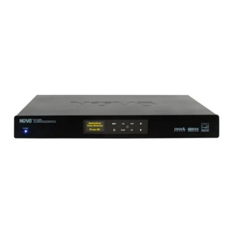
Nuvo NV-I8DM User manual

NV-T2SIR
Dual SIRIUS®-Ready/AM/FM Tuner
Installation Guide


FRENCH
DURE EN HEURES PAR JOUR 8 6 4 3 2 1
INIVEAU SONORE CONTINU EN dB 90 93 95 97 100 103
Danger
L‘exposition a des niveaux eleves de bruit peut provoquer une perte
permanente de l’audition, Chaque organisme humain reagit
differemment quant a la perte de l’audition, mais quasiment tout le
monde subit une diminution de I’acuite auditive lors d’une exposition
suffisamment longue au bruit intense. Les autorites competentes en
reglementation de bruit ont defini les expositions tolerees aux niveaux
de bruits:
Selon les autorites, toute exposition dans les limites citees ci-dessus,
peuvent provoquer certaines pertes d’audition. Des bouchons ou
protections dans l’appareil auditif ou sur l’oreille doivent etre portes lors
de l’utilisation de ce systeme d’amplification afin de prevenir le risque
de perte permanente de l’audition, Dans le cas d’expositions
superieures aux limites precitees il est recommande, afin de se
premunir contre les expositions aux pressions acoustiquese I evees
potentielIement dangeure u ses, aux personnes exposees aux
equipements capables de delivrer de telles puissances, tels ce
systeme d’amplification en fonctionnement, de proteger l’appareil
auditif.
ATTENTION: AFIN DE LlMlTER LE RISQUE DE CHO ELECTR/QUE, NE
PAS ENLEVER LE CHASSIS. NE CONTIENT PAS DE
PIECES POUVANT ETRE REPAREE PAR L’UTILISATEUR.
CONFER LE SERVICE APRES-VENTE AUX
REPARATEURS
ATTENTION
RISQUE DE CHOC ELECTRIQUE
NE PAS OUVRIR.
CE SYMBOLE A POUR BUT D'AVERTIR L'UTILISATEUR DE LA PRESENCE
DE VOLTAGE DANGEREUX NON-ISOLE A L'INTERIEUR DE CE PRODUIT
QUI PEUT ETRE DE PUISSANCE SUFFISAMMENT IMPORTANTE POUR
PROVOQUER UN CHOC ELECTRIQUE AUX PERSONNES.
CE SYMBOLE A POUR BUT D'AVERTIR L'UTILISATEUR DE LA PRESENCE
D'INSTRUCTIONS D'UTILISATION ET DE MAINTENANCE DANS LES
DOCUMENTS FOURNIS AVEC CE PRODUIT.
IMPORTANTES INSTRUCTIONS DE SECURITE
1. Lire avec attention toutes les recommandations et précautions
d'emploi avant d'utiliser ce produit.
2. Toutes les recommandations et précautions d'emploi doivent être
conservées afin de pouvoir s'y reporter si nécessaire.
3. Lire et comprendre tous les avertissements énumérés dans les
précautions d'emploi.
4. Suivre toutes les précautions d'emploi pour utiliser ce produit.
5. Ce produit ne doit pas être utilisé près d'eau, comme par exemple
baignoires, éviers, piscine, sous-sol humides ... Etc.
6. Utiliser exclusivement un chiffon sec pour nettoyer ce produit.
7. Ne bloquér aucune ouverture de ventilation. Ne pas placer le
produit tout contre un mur ou dans une enceinte fernée, cela
gênerait le flux d'air nécessaire au refroidissement.
8. Ne pas placer le produit près de toute source de chaeur telle que
radiateurs, arrivées d'air chaud, fourneaux ou autres appareils
générant de la chaleur (incluant les amplificateurs producteurs
de chaleur) .
9. Ne pas négliger la sécurité que procure un branchement polarisé
ou avec raccordement à la terre, Un branchement polarisé
comprend deux fiches dont l'une est plus large que l'autre. Un
branchement à la terre comprend deux fiches plus une troisième
reliée à la terre. Si la fiche secteur fournie ne s'insert pas dans
votre prise de courant. consulter un 'électricien afin de remplacer
votre prise obsolète.
10. Protéger le cordon d'alimentation de tout écrasement ou
pincement, particulièrement au niveau des fiches, des
réceptacles utilisés et à l'endroit de sortie de l'appareil. Ne pas
casser la fiche de terre du cordon d'alimentation.
11. Utiliser uniquement les accessoires spécifiés par le constructeur.
12. Utiliser uniquement avec le chariot de transport, le support, le
trépied, la console ou la table spécifiés par le constructeur ou
vendus avec l'appareil. Lors de l'utilisation d'un chariot, bouger
avec précaution l'ensemble chariotlappareil afin d'éviter les
dommages d'un renversement.
13 Débrancher cet appareil lors d'orages ou s'il n'est pas utilisé
pendant une longue période.
14. Des précautions doivent être prises afin qu'aucun objet ne tombe
et qu'aucun liquide ne se répande à l'intérieur de l'appareil par
les orifics de ventilation ou n'importe quelle autre ouverture.
15. Pour toutes interventions techniques s'adresser à un technicien
qualifié.L'intervention technique est nécessaire lorsque l'appareil
a été endommagé de n'importe quelle façon, comme par
exemple si le cordon secteur ou sa fiche sont détériorés,si du
liquide a coulé ou si des objets sont tombés à l'intérieur de
l'apparei1,si l'appareil a été exposé à la pluie ou à l'humidité, s'il
ne fonctionne pas normalement ou s'il est tombé.
16. ATTENTI0N:Pour réduire le risque d'incendie ou de choc
electrique ne pas exposer l'appareil à la pluie ou à l'humidité.
AFIN DE REDUIRE LES RISQUÉ D'INCENDIE ET DE DECHARGE
ELECTRIQUE, NE PAS EXPOSER CET APPAREIL A LAPLUIE OU A
L'HUMIDITE.

GROUND
CLAMPS
ELECTRIC
SERVICE
ENTRANCE
ANTENNA
DISCHARGE UNIT
NEC SECTION
810-20
GROUNDING
CONDUCTORS
GROUND CLAMPS
POWER SERVICE
GROUPING ELECTRODE
SYSTEM NEC ART 250
PART H
NEC NATIONAL ELECTRICAL CODE
ANTENNA
LEAD-IN
WIRE

Introduction
CongratulationsonyourpurchaseoftheNuVoT2SIRDualSIRIUSReady/AM/FMTuner.Enjoyingbroadcastmusicthroughoutthe
st
homehasmovedintothe21centurywithNuVo’sT2DualTunersolutions.WhetheryourpreferenceistraditionalAM/FMlistening,
orSIRIUSSatelliteRadio,theT2SIRoffersanaffordable,speciallydesignedcomponentforwhole-homedistribution.
TheT2SIR’sinternalNuVoNetcommunicationallowsforveryuniqueandcompletefeedbacktoalloftheNuVoControlPads.
1
Table of Contents:
Basic Features
I. Installing the T2SIR in the Home
SettingtheAudioOutputsforNuVoNetor
II. T2SIR Use with SIRIUS Radio
III. T2SIR Front Panel Menu
T2SIR Quick Setup Guide for Use with NuVoNet page2
FrontPanel page4
BackPanel page5
NV-T2RC4RemoteControl page6
ConnectingtheAudioOutputs page7
Standaloneuse page7
AM/FMAntennaInstallation page7
ConnectingforNuVoNetUse page8
IRControloftheT2SIR page8
RS232SerialControl page9
TheSIRIUS8-pinConnector page9
SIRIUSModulesandSubscription page9
InstallingtheSIRIUSAntenna page10
Bands page10
Channels page11
SIRIUSInfo page11
T2SIROptions page11
EditPresets page11
TuningMode page12
SkippedChannels page12
T2SIRSettings page13
OperatingMode page13
EnabledBands page13
Tuning page13
Diagnostics page14
AudioTest page14
ResetMemory page14
IV. NuVoNet Control of the T2SIR
V. Using the Tuner Configurator Software
Advanced Settings
TuningUpandDown page15
SelectingaLockedChannel page15
ChangingBands page15
TuningModes page15
SelectingTunerAandB page15
ControlPadMainMenu page16
T2SIROptions page16
1.0Start page18
2.0Config page18
3.0Presets page20
4.0AdvancedConfig page22
5.0UpdateSystem page23
NV-T2SIR Specifications page24

2
T2SIR Quick Setup Guide for Use With NuVoNet
TheT2SIRDualTuneristheperfectbroadcastmusicsolutionforwhole-homeaudio.TheinternalNuVoNetcapabilityoftheT2SIR
allowsittoeasilycommunicateinrealtimewiththeNuVoGrandConcertoandEssentiaE6GControlPads.Thefollowingisastep-
by-stepguideforsettingupandinstallingtheT2SIRforusewiththeGrandConcertoandEssentiaNuVoNetSuites.
Step 1: UponunpackingyourT2SIRTuner,establishwhichaudioinputs,1-6,theT2’sAandBaudiooutputswillrepresent.Plug
theT2intoanACpowersource.
Step 2: AttachtheaudiooutputsAandBoftheTunertotheappropriatenumberedinputsontheGrandConcertoorEssentia
System.
Step 3: ConnecttheCAT5fromtheNuVoNetoutputontherearpaneloftheTunertooneoftheDeviceinputsontheGrandConcerto
EZPortortheEssentiaAllport.ThiswillenablecommunicationtotheSystem’sControlPads.NotethatasingleCAT5connection
providesinformationfrombothTunersAandB.AfinalCAT5ConnectionshouldthenbemadetotheNuVoNetCAT5inputonthe
backpaneloftheGrandConcertoorEssenitamainamplifierfortheNuVoNetRJ45ontheGrandConcertoEZPortortheEssentia
Allport.ThiscompletesthenecessaryconnectionfortheNuVoNetcommunication.
T2SIR Wiring Diagram
IN
OUT1 OUT2
MODELSRS-2V8
2300-2400MHZ
072 8
303 3118
R
T
E
E
T
K
N
I
CM
Model NV- T2S IR
Dua l SIRIU S Ready AM /FM Tune r
www. nuv otec hnol ogie s.co m
NuVo Techno log ies LL C H ebro n, KY US A•
CONF ORMS TO UL
STD. 6006 5 CERTIF IED
TO CAN /CSA STD .
C22. 2 No.6 0065:0 6
RS 232
SYSTE M
ANTEN NA
IN NuVoNe t
USE N V-T2 DAA WIT H
OPT IONAL NV-T2 FXC
AND SIRI US ANTE NNA
IR INPUT
L
AUDIO
R
TUNER A
SIRIUS L
AUDIO
R
TUNER B
RoHS
SIRIUS
R
OUTPUT POWER OUTPUT POWER
20W/6OHM X2 20W/6OHM X2
SYS ON
EXT. MUTE
L
R
L
R
L
R
VARI ABLE
OUT PUT
FIX ED
OUT PUT
SUM1
3033 118
CUS
CON FORMS T O
UL ST D.65 00
CER TIFIE D TO
CAN /CSA S TD.E 6006 5
NuVo Tec hnolo gies C incin nati Oh io USA
FUS E:T5 A
120 V 60H z 500W
MODE L NV-I8DM
SIX SO URCE EI GHT ZON E
AUDI O DISTR IBUTI ON SYST EM
www. nuvote chnolo gies.c om
OUTPUT POWER
OUTPUT POWER
OUTPUT POWER
20W/6OHM X2
20W/6OHM X2
20W/6OHM X2
TIP =L
RIN G=R
VARI ABLE
OUT PUT
FIX ED
OUT PUT
T IP=L
RIN G=R
VARI ABLE
OUT PUT
FIX ED
OUT PUT
T IP=L
RIN G=R
VARI ABLE
OUT PUT
FIX ED
OUT PUT
T IP=L
RIN G=R
VARI ABLE
OUT PUT
FIX ED
OUT PUT
T IP=L
RIN G=R
VARI ABLE
OUT PUT
VARI ABLE
OUT PUT
FIX ED
OUT PUT
FIX ED
OUT PUT
T IP=L
RIN G=R
T IP=L
RIN G=R
1 2 3 4 5 6
1 2 3 4 5 6
2 3 41 2 3
RS-232
CON NECT TO
NV-I 8X
USE N V-SLC1
CAB LE
CON NECT TO
NV-I 8X
USE N V-SLC1
CAB LE
CON NECT TO
NV-I 8EZP 1
USE N V-NC1
CAB LE
USE CNLY WITH 250V FUSE
456SUM2
5 6 7 8
OUTPUT POWER
20W/6OHM X2
ZONE 6Z ONE 6 ZONE 7&8
SYSTEM
ZONE TRIGGER OUTPUTS
SOURCE LINK
SOURCE INPUTS
ZONE 1
NETWORK
EMITTER OU TPU TS DIGITAL LINK
ZONE 3 ZONE 4 ZONE 5
ZONE 2 PROGRAM
6
45
31
2
SOURCE STATUS INPUT S
1
MENU OK
Modern Rock
Drift-Follow Th
Living For
AM/FM 3:09 pm
AM/FM
ANTENNAIN
XM
ANTENNAIN
COMBINED
ANTENNAOUT
NV-T2FXCSIGNAL
COMBINER
AM/FM
ANTENNAIN
XM
ANTENNAIN
COMBINED
ANTENNAOUT
NV-T2FXCSINGNAL
COMBINER
Diagram shown using the Grand Concerto System
Diagram shown using an optional NV-SCH-ANT SIRIUS Outdoor Antenna
and two SIRIUS NV-SCH1 Home Tuners.
Conc erto EZ Port
Mode l NV-I8GEZP
Device 2 Device 3
Device 4 Device 5 Devi ce 6
Conn ect to
NV-I8 GM
www.nuv ote ch no log ies .co m
NuVo Techno logies LLC Hebr on, Ke ntuck y USA
Device 1

3
Step 4: CompletetheantennaconnectionsonthebackpaneloftheTunerusingstandardRG6coaxialcable.Quadshieldedcableis
recommended.Whentheantennasareconnected,theTunerwillbeginreceivingasignalforbothTunersAandB.
Step 5: WhentheTunerispluggedintoanACpowersource,thefrontpaneldisplaywillmovethroughabootprocedure.Whenthis
procedureiscompleted,amessage, UninitializedStateDetected willappear.
Step 6: Followingthepromptfromthedisplay,touchtheOKbuttonontheTuner’sfrontpanelcontrol.Thiswilldisplayaregional
tuningselection:USAandCanada,WesternEurope,Australia,andNewZealand.Maketheappropriateselectiontomatchthe
Tuner sgeographiclocation.
Step 7: TouchingOKonthefrontpanelcontrolswillpromptasecondscreenonthedisplay.Thiswillread,Set Tuner A Mode,
Standalone, Source 1, Source 2, Source 3, Source 4, Source 5, and Source 6. Thetopselection,Standalone, willbehighlighted.This
choiceisusedforanypurposethatisnotNuVoNetcommunication.Usingthedownarrowonthefarrightofthefrontpanel
controls,scrolltothedesiredsourceinputnumberandtouchOKtoselect.ThedisplaywillautomaticallygotoTunerBsetup.
RepeattheabovestepsforsettingTunerB.IfNuVoNetisnotconnectedorallavailablesourceshavebeenassigned,thanthe
sourceselectionswillbegrayedout.
Step 8: Whenthedesiredsourcenumberisselected,thedisplaywillreturntothefirstscreen.BothoutputsAandBwilldisplay
thelowestFMbandfrequencybydefault.Atthispoint,fulltuningcapabilitycanbedonefromtheTuner’sfrontpaneloran
addressedNuVoControlPad.
Step 9: WhenbothTuneroutputsareset,makesurethe NuVoNet CAT5connectionbetweentheTuner sbackpanelandthe
systemEZPortiscompleted.
TheT2SIRTunerisnowreadyforNuVoNetcommunicationwitheithertheGrandConcertoorEssentiaE6Gdistributedaudio
systems.
PleaseseethecompleteinstallationguideforunderstandingthefulluseofyourT2SIRTuner.

MENU
BAND OK
A/B
DISP
NV-T2SIR
Dual SIRIUS Ready AM/FM Tuner
STANDBY
RADIO DATASYSTEM
Sr6
Give Me The Night
FM 103.5
Ticket To Ride
P103
P104 ST
1 4
5
6
7
8
9
101112 14
23
Front Panel Features
1. Standby: ThisblueLEDwilllightwhentheT2SIRispluggedintoanACpoweroutlet.
2. Tuner Highlight: ThishighlightbarshiftsbetweentheTunerAandBdisplaytoindicatewhichTunerisbeingcontrolled.
3. Broadcast Band Display: Thislineofthefrontpaneldisplayshowstheselectedbroadcastbandandfrequencyorchannel.The
bandsavailableareAM,FMandoptionalSIRIUS.
4. Metadata Display: ThislineofthedisplayscrollsRDS,RadioDataService,informationforFMandSIRIUSRadiobroadcast
informationwhenaSIRIUS-Readyreceiverisconnected.
5. Preset Number: TheT2SIRfeaturesupto5banksof20presetseach.Thisindicatesthenumberofthepresetbankofthe
selectedpreset.
6. Antenna Signal: Thelevelofsignallevelisindicatedwithuptofivebars,fivebeingthebest.WhenlisteningtoFM,fullstereo
receptionisindicatedwithanabbreviatedST.
7. Menu: ThiscapacitivetouchpanelallowsfrontaccesstotheT2SIR’scontrolsaswellaspresetlisteningselectionsandtuning
parameters.
8. Power: Thisbuttonturnsthepowerforthefrontpaneloffwhentapped,andcausesasoftrebootoftheoperatingsystemwhen
itisheldfor3seconds.
9. A/B: BytappingtheA/Bbutton,thehighlightedTuneroutputandcontroltogglesbetweenAandB.
10. Band: TheBandbuttontogglesbetweenAM,FMandSIRIUSwhenitisactivatedforthehighlightedTunerAorB.
11. IR Window: TheT2SIRwillbecontrolviaIRthroughitsfrontpanelIRreceiver.
12. OK: OkinitiatesahighlightedMenuchoice.
13. Disp: ThisbuttontogglesthroughthetuningchoicesforSIRIUS.ThisisonlyfunctionalwhenSIRIUSreceptionisactivated.
14. Up and Down Arrows: ThesearrowbuttonsprovidemultiplefunctionsdependingonthemodeoftheTuner.Innormal
operation,theyinitiatetuningupanddownthroughtheselectedband.Wheninmenumode,theyscroll
upanddownthroughthemenuchoices.
4
13

0728
3033118
R
T
E
E
T
K
N
I
CM
Model N V-T2 SIR
Dual SIRIUS R ead y AM/F M Tuner
www.nu votechnolo gie s.com
NuVo Tec hno logies LLC H ebr on, K Y USA•
CON FORMS TO U L
STD .6006 5 CERTI FIED
TO CA N/CSA ST D.
C22 .2 No.6 0065: 06
RS 232
SYSTEM
ANTENNA
IN NuVoNet
USE NV-T 2FAA
ANTENNA
IR INPUT
L
AUDIO
R
TUNER A
SIRIUS L
AUDIO
R
TUNER B
RoHS
SIRIUS
14567
23
Back Panel Features
1.Antenna Input: Thissingle F connectoristhecoaxialcableconnectionbetweentheT2SIRandtheincludedNV-T2FAAAM/FM
antenna.
2.Audio Output: TheaudiobroadcastforAM,FM,orSIRIUSSatelliteRadioreceivedbytheTunermoduleisavailablethroughthis
stereoRCAoutput.TunerAandBofferindependentaudiooutputsforusewiththeNuVoaudiosystemsorthird
partyreceiversandamplifiers.
3.SIRIUS: Thiseight-pinconnectionisauniversalSIRIUScommunicationport.ItallowsathirdpartySIRIUSTunermoduletofully
communicatewiththeGrandConcertoorEssentiaE6GNuVoNetSystems.
4.IR Input: TheT2SIRoffersasinglestereomini,3.5mmconnectionforindependentIRcontrolofbothTunerAandB.
5.NuVoNet: ThissingleCAT5connectionprovidesfullNuVoNetcommunicationforbothTunersAandBtotheNuVoGrandConcerto
andEssentiaE6Gaudiodistributionsystems.ThisconnectionismadeattheGrandConcertoEZPortortheEssentia
E6GAllport.
6.RS232: ThisDB99-pinconnectorisusedforconfigurationprogramming(seepage17,V. Using the Tuner Configurator
Software)andbidirectionalserialcontrolfromathirdpartyhomeautomationcontroller.
7.AC Power: TheT2SIRisdesignedtoplugintoanyACpowersource.
5

123
456
7 8 9
0OK
AM
FM
DAB SAT
DISP
BAND
PWR A/B
PRE
T2 Tuner
NV-T2RC4
REMOTE CONTROL
TUNER
1
2
3
4
5
6
7
8
9
10
11
12
13
P
C
P
C
TUNE
NV-T2RC4 Remote Control
1.Power: ThepowerbuttonturnstheTuneronandoff.
2.Tune Buttons: ThesebuttonsaretheequivalentofusingtheUpandDownarrowsonthefrontpaneloftheT2SIRtotune.
3.Band: ThisbuttontogglesthroughtheTuner savailablebroadcastbands.
4.Seek Up and Down: TheseekbuttonswilltunetothenextavailablestationwiththerequiredsignalstrengthforAMand
FMuse.ThesignalthresholdcanbeadjustedhigherorlowerusingtheTunerConfiguratorsoftware
(seepg.18),orthroughtheT2SIROptionsmenuonthefrontpanel(seepg.10).
5.Preset Tune: Thesebuttonsstepthroughtheassignedpresets.TheT2SIRiscapableof5banksof20presets.
6.Category Tune: CategoryTuneisnotimplementedonthismodel.
7.Pre: Thisbuttonisusedtoestablishapresetbankandpresetnumberforthefrequencybeingdisplayedontheselected
Tuner.Totunetoaspecificpreset,push Pre followedbythebanknumber(1-5)thenthe2-digitpresetnumber
(01-20).
8.Tuner A & B LED: ThisLEDglowsredwhenTunerAisselectedandgreenwhenTunerBisselected.ThisLEDglowsonly
momentarilywhenabuttonispushed.
9.A/B: ThisbuttontogglesbetweenTunerAandTunerBoperation.
10.Disp: ThisbuttonfunctionsonlyforNorthAmericansatelliteradiouse.
11.Numeric Buttons: Thesebuttons(0-9)areusedtoaccessaspecificstationfrequencyorpreset.
12.OK: ThisisaselectbuttonusedforsavingpresetsorenteringanAMorFMfrequency.
13.Band Buttons: ThesefourbuttonsareadirectselectforthetuningbandsavailablethroughtheT2Tuners.Actual
functionalitydependsonthemodelTunerbeingcontrolled.
6

7
I. Installing the T2SIR in the Home
Connecting the Audio Outputs (Fig. 1)
TheT2SIRhastwoindependentaudiooutputslabeledAandB.
ThesearestandardstereoRCAconnectionsandcanbe
connectedtoanydevicedesignedtoreceiveananalogstereo
audiosignal.
Setting the Audio Outputs for NuVoNet or Standalone use
(Fig. 2)
TheoutputsAandBareindividuallysetfromthefrontpanel
displayoftheT2SIR.WhentheTunerisinitiallypluggedinto
anACpowersource,ashortsetupwizardwillappearonthe
display.Amessage, UninitializedStateDetected(PressOK)
willappear.WhenOKispressed,thepromptistoselecta
regionaltuningstandard.ThechoicesareUSA/Canada,
WesternEurope,Australia,andNewZealand.UsetheUpand
Downarrowstohighlighttheappropriatechoiceandtouchthe
OKbuttontoselectthis.Onceregionaltuninghasbeen
selected,thedisplaywillpromptfortheuseofeachoutputA
andB.UsingtheUpandDownarrowsonthefrontpanel,move
thehighlighttotheappropriateuseoftheTuneroutputand
touchOK.ThechoicesareStand Alone, Source 1, Source 2,
Source 3, Source 4, Source 5, and Source 6. Foranyuseother
thanwiththeEssentiaE6GorGrandConcertoSystems,select
Standalone.ThiswillrequireIRorserialcontroloftheT2SIR’s
functions.HighlightingtheappropriateSourcenumberinput
fortheNuVosystemandtouchingtheOKbuttonsetsNuVoNet
communication.OnceOutputAisset,thehighlightwillmove
toOutputB.Foroperation,bothoutputsAandBmustbesetas
StandaloneorasaNuVoNetSource.
WhentheTuner’soutputsareset,theywillreturntoFM87.9,
ortheminimumFMbandsettingfortheselectedregional
tuningparameters.AtthispointtheT2SIRisreadyforeither
NuVoNetcommunicationorstandaloneuse,dependingonthe
settingmadeforbothoutputs.
ANTENNA
IN
USE N V-T2FAA
ANTENNA
L
AUDIO
R
TUNER A
SIRIUS L
AUDIO
R
TUNER B
SIRIUS
SOURCE L INK
L
R
L
R
L
R
SOURCE I NPUT S
TIP =L
RIN G=R
ZONE 2
VARI ABLE
OUT PUT
FIX ED
OUT PUT
TIP=L
RIN G=R
VARI ABLE
OUT PUT
FIX ED
OUT PUT
TIP=L
RIN G=R
VARIA BLE
OUT PUT
FIX ED
OUT PUT
TIP=L
RIN G=R
1 2 3 4 5 6
1 2 3 4 5 6
1 2 3
4
CON NECT TO
NV-I 8X
USE N V-SLC1
CAB LE
56
ZON E 1
VARI ABLE
OUT PUT
FIX ED
OUT PUT
SPE AKER
40W /6 OHMS X 2
LEF T RIGHT
ZONE 3 ZO NE 4
SOURCE S TATU S
SPE AKER
40W /6 OHMS X 2
LEF T RIGHT
SPE AKER
40W /6 OHMS X 2
LEF T RIGHT
SPE AKER
40W /6 OHMS X 2
LEF T RIGHT
Fig. 1
Fig. 2
MENU
BAND OK
A/B
DISP
Uninitialized
State Detected
(Press OK)
MENU
BAND OK
A/B
DISP
Regional Setup
US and Canada
Western Europe
Australia
MENU
BAND OK
A/B
DISP
Set TunerA Mode
Standalone
Source 1
Source 2

8
AM/FM Antenna Installation (Fig. 3)
TheT2SIRisshippedwiththeNV-T2FAAactiveAM/FM
antenna.Theantennaisdesignedtoworkactivelywiththe
Tunerusingstandard75-ohmcoaxialcable.Quad-shielded
cableisrecommendedforthispurpose.Theadvantageofthe
activeantennatechnologyistheremotelocationcapability,up
to200feetfromtheT2SIRlocation,withouttheneedforan
externalpowersupply.Theterminationattheantennaand
Tunerisastandard F styleconnector.Nosoftware
applicationorconfigurationisnecessarybeyondmakingthe
cableconnectionateachend.
Note, for best results, the T2FAA antenna should be located as
high as possible, either in an attic or outside. If you choose to
use a third party antenna, other than the T2FAA, you must use
the forced off setting from the menu to allow the signal to pass
through to the T2SIR, (seesectionIII.T2SIR Front Panel Menu,
Antenna Power, pg.14).
Connecting for NuVoNet Use (Fig. 4)
OnceaudiooutputsAandBaresetforNuVoNet,theT2SIRis
readytocommunicateinrealtimewiththeGrandConcertoor
EssentiaE6Gaudiodistributionsystems.Tocompletethe
connection,allthatisnecessaryisasingleCAT5cablefromthe
NuVoNetoutputontheT2SIR’sbackpaneltooneoftheDevice
inputsoneithertheGrandConcertoEZPortortheEssentiaE6G
Allport.SincetheoutputsoftheTunermustbesetasaspecific
sourcenumberinputforNuVoNetcommunication,thenumber
oftheDeviceconnectionusedisirrelevanttothesystem’s
operation.Oncetheconnectioniscomplete,theTunerisready
tofullycommunicatewithNuVoNet.
IR Control of the T2SIR (Fig. 5)
TheT2SIRcanbeusedwithoutNuVoNetasastandalone
AM/FM/SIRIUS-ReadyTuner.TheIRreceiverisalwaysactive,
howevercontrolthroughIRistypicallydoneinStandalone
mode,(seesectionI.Setting the Audio Outputs for NuVoNet or
Standalone use, pg.7).
Fig. 3
Fig. 4
MENU
OK
Jozef Kossovit
SIR
SR 86 (P101)
SIRIUS Pops
3:09 PM
Hungaria
0728
3033 118
E
R
T
E
T
K
N
I
CM
Mod el NV-T2 SIR
Dual S IRIU S Ready AM /FM Tuner
www. nuvote chnolo gies .com
NuVo Tec hnolog ies LL C Hebron , KY USA•
CONF ORMS TO UL
STD. 60065 CE RTIF IED
TO CAN/C SA STD.
C22. 2 No.600 65:0 6
RS 23 2
SYSTEM
NuVoN et
IR IN PUT
RoHS
The NuVo active
antenna can be located up
to 200 feet from the T2SIR
Tuner.
ANTEN NA
IN
USE N V-T2FAA
ANT ENNA
L
AUDIO
R
TUNER A
SIRIUS L
AUDIO
R
TUNER B
SIRIUS

9
OncetheaudiooutputsaresetatStandalone,theT2SIRoffers
threemethodsforIRcontrol.OneistotaketheIRoutputof
yourcontroldeviceusingamono3.5mmpatchcableplugged
intotheDirectIRinputonthebackpaneloftheT2SIR.TunersA
andBfeaturediscretecommands,allowingbothTunerstobe
controlledindependentlyfromoneinput.Thesecondmethod
forIRcontrolistoattachanIRemitterovertheIRreceiveron
thefrontpanel,andthethirdmethodistoaimtheremote
controlattheIRreceiverlocatedonthefrontpanel.
RS232 Serial Control
TheT2SIRfeaturesabidirectionalDB9portforserialcontrol.
ThisenablestheTunertobecontrolledviaathirdpartyhome
automationsystemandwillinturnissuepresentstate
commandsbacktothecontroller.Potentially,allaspectsof
NuVoNetcommunicationcanbeemulatedusingtheserial
controlcapability.Thenecessaryprotocolforserialusecanbe
downloadedfromtheNuVowebsiteProZoneat
SYSON
EXT.MUTE
SYSTEM
ZONETRIGG ER OUTP UTS
NETWORK
SUM1
EMITTEROU TPUTS
3033118
CUS
R
CONFORMSTO
ULSTD.6500
CERTIFIEDTO
CAN/CSASTD.E6 0065
NuVoTechnologies Ci ncinn ati Oh io USA
FUSE:T5A
120V 60Hz50 0W
MODELNV-I8M
SIXSOURCEEIGHT Z ONE
AUDIODISTRIBUTION SY STEM
www.nuvotechnologie s.com
DIGITALLIN K
VARIABLE
OUTPUT
FIXED
OUTPUT
TI P=L
RING=R
VARIABLE
OUTPUT
FIXED
OUTPUT
TI P=L
RING=R
VAR.
OUT
FIX.
OUT
PROGRAM
1 2 3 41 2 3
CONNECTTO
NV-I8X
USENV-SLC1
CABLE
CONNECTTO
NV-I8EZP1
USENV-NC1
CABLE
USECNLYWITH250VFUSE
456SUM2
5 6 7 8
ZONE5 ZONE6 ZONE 7 ZONE 8
RS 232
SPEAKER
40W/6OHM S X 2
LEFT RIGHT
SPEAKER
40W/6OHM S X 2
LEFT RIGHT
SPEAKER
40W/6OHM S X 2
LEFT RIGHT
0728
3033118
R
T
E
E
T
K
N
I
CM
Model NV -T2 SIR
Dual SIRI US Ready AM/FM Tuner
www.nuvot echno logi es. com
NuVo Techno log ies LLC Hebr on, KY USA•
CONFORMS TO UL
STD.60 065 CERTIFIED
TO CAN/CSA STD.
C22.2 No.60 065:0 6
RS 232
SYS TE M
NuVoNet
IR INPUT
RoHS
Fig. 5
Fig. 6
Fig. 7
II. T2SIR Use with SIRIUS Radio
The SIRIUS 8-Pin Connector (Fig. 6)
EachTuner,AandB,hasaSIRIUS-Readyconnectoronitsback
panel.ThisconnectorisreadytoreceivetheTunersignaland
relatedmetadatafromaSIRIUSreceiver.AnySIRIUSreceiver
equippedwiththeSIRIUSconnectorwillcommunicatewiththe
T2SIR’sinput.Thecablenecessaryforthisconnectionis
typicallysuppliedwiththeSIRIUSreceiver.Oncethe8-pin
connectionismadefromtheSIRIUSreceivertotheT2SIR,
SIRIUSwillberecognizedasaradiobandforeitherTunerAor
B.
SIRIUS Modules and Subscription (Fig. 7)
ThereisnotaspecificSIRIUSreceiverthatmustbeusedin
conjunctionwiththeT2SIR.Severalareonthemarket,andthe
onlypre-requisiteisthatthereceiverusedhasthe8-pin
SIRIUS-Readyconnector.NuVodoeshavetheNV-SCH1home
receivermoduleasaconvenient,inexpensivesolutionforthe
T2SIR.EachSIRIUSTunerhasanIDassociatedwithit.This
numberistypicallyfoundprintedontheSIRIUSTunerorby
goingtotheT2SIRSIRIUSInfomenu.EachattachedSIRIUS
receivermustbeactivatedusingitsIDnumber.
ANTENNA
IN
USE NV-T 2FAA
ANTENNA
L
AUDIO
R
TUNER A
SIRIUS L
AUDIO
R
TUNER B
SIRIUS
SIRIUS-Ready 8-pin connectors
ANTEN NA
IN
USE N V-T2FAA
ANTENNA
L
AUDIO
R
TUNER A
SIRIUS L
AUDIO
R
TUNER B
SIRIUS
Diagram shown using a NV-SCH1 SIRIUS Home Tuner

10
Your SIRIUS Tuners must be activated through SIRIUS. This can
be done online at www.SIRIUS.com.
Installing the SIRIUS Antenna (Fig. 8)
ThereareseveralversionsofSIRIUSantennasonthemarket.
TheantennasbestsuitedforusewiththeT2SIRaredesigned
foroutsideplacement,suchastheNV-SCH-ANTalsoavailable
fromDirectedElectronicsasmodel14245.Anantennawithan
F connectordesignedforusewithcoaxialcableis
recommended.Oftenitisnecessaryfortheantennatohavean
unimpededviewoftheskytoreceiveasignal.Figure8shows
thistypeofapplicationwiththeNV-SCH-ANTantennawithits
includedsignalsplitterforusewithtwoSIRIUSreceivers.The
T2SIRisshippedwithtwoNV-T2FSDAM/FM/Satellite
Diplexers.ThisallowstheAM/FMandSIRIUSsignalstobe
combinedandbroughttothebackoftheTuner.There,the
secondNV-T2FSDcanbeusedtosplitthesignalasecondtime.
ThisallowstheAM/FMsignaltocomeintotheantennainput
ontheT2SIRbackpanelandtheSIRIUSsignalisthenroutedto
theSIRIUSreceiverorreceivers,dependingontheapplication.
ItisnotnecessarytoplacetheAM/FMandSIRIUSantennasin
thesamelocation.
It is important to note that Directed Electronics has an outdoor
antenna, model 14240, that has a 50 ohm connection intended
for RG58 cable. This model is not recommended for use with the
NV-T2SIR Tuner.
III. T2SIR Front Panel Menu (Fig. 9)
TheMenubuttononthefrontpaneloftheT2SIRallowsaccess
tothetuningandfunctionalityofbothTunersAandB.The
menuselectionsarethesameforboth,andtouchingtheA/B
buttonmovesthehighlightbetweenthetwoTuneroutputs.
Bands (Fig. 10)
TheBandsmenuisasimpletogglethroughtheavailable
broadcastbandsofeachTuner.SIRIUSisonlypresentifa
SIRIUSreceiverhasbeenpluggedintoeitherTunerAorB.The
currentlyselectedbandwillbedisplayedwithacheckmark.
MENU
BAND OK
A/B
DISP
Main Menu
Bands
Channels
My Presets 1
Fig. 9
Fig. 8
Fig. 10
Main Menu
FM
AM
SIRIUS
IN
OUT1 OUT2
MODEL SRS-2V8
2300-2400MHZ

11
SIRIUS Info (Fig. 12)
Therearetwosub-menuswithinthischoice.Itisonlyactiveif
theSIRIUSinputfortheselectedTunerisbeingused.
SIRIUS ID: ThisdisplaystheIDnumberassociated
withtheconnectedSIRIUSTuner.Thisnumberis
referencedwhenactivatingtheTunerthroughSIRIUS,
orforcustomerserviceissues.
Now Playing Info: Thisscrollsthemetadatafora
selectedSIRIUSChannel.
T2SIR Options (Fig. 13)
Theoptionsmenuhasthreemaintuningsub-menus.Theseare
tuningdefaultsthatcanbeset:
Edit Presets (Fig. 14): Thisisagreattoolfor
allowingacurrentlyselectedchanneltobe
savedasapreset.Asanumberpresetis
selected,thedisplaywillpromptto Assign
tocurrentchannel .Whenselected,the
T2SIRwillsavethefrequencyandassociated
shortnameofthechannel.Thereare5banks
of20presetseachavailable.Toaddapreset
tofavorites,highlightandselectanexisting
preset.Thiswillbringupasecondmenuwith
severalchoices:Delete Preset, whichwill
erasethehighlightedpresetfromthelist;
Add to Favorites placesthehighlightedpreset
intotheFavoritesmenuavailableateach
ControlPad;Move Up andMove Down moves
thehighlightedpresetupordownwithinthe
listofpresets;Move to Top andMove to
Bottom placesthehighlightedpresetinthe
number1positionortothelastavailable
position.
T2SIR Options
Edit Presets
Seek Tune
Tuning Mode
Fig. 12
Fig. 13
Fig. 14
SIRIUS Info
SIRIUS ID
Now Playing I..
Edit Presets
Delete Preset
Add to Favori...
Move Up
Channels (Fig. 11)
TheChannelmenuisaSIRIUSfunction.Itisaquickaccessto
thecategoriesassociatedwithSIRIUS.Whenselected,each
categorywillexpandtodisplaytheassociatedchannels.When
theSIRIUSinputisnotinuse,thiswillappeargrayedout.
Fig. 11
Channels
All SIRIUS Cha
Pop
Rock

12
Tuning Mode (Fig. 15): TuningModehasfourchoices
thatsetdefaultsforthewayinwhichtheT2SIRwill
tunethroughchannelsorfrequencies.TheSIRIUSonly
functionswillbegrayedoutwhenaSIRIUSreceiveris
notpresent.
Seek Tune (Am/FM only): SeekTunesearches
forstrongfrequenciesinAM/FMbandsand
willstopatthenextfrequencythatmeetsthe
settuningparameters.Thismenuoption
turnsseekonoroff.WhenSeekTuneis
turnedoff,StepTuneisthedefault.
Preset Tune: Whenturnedon,thePresetTune
modewillonlystopatchannelsor
frequenciesthathavebeensavedaspresets
inthecurrentband.
Parental Lock (SIRIUS only) (Fig. 16): This
requiresa4-digitsecuritycode.Thedefault
parentallockcodeis5555.Toaccessthesub-
menus,youmustenterthedefault5555.This
isdonebyusingtheUparrowtoscrolltothe
first5,thentouchingOKonthefrontpanel
movesthehighlighttothesecondnumber.
When5555isset,youwillthenhaveaccess
totheParentalLocksetup.
Set Security Code (Fig. 17): Thislets
yousetanewcodeforParentalLock
purposes.Thenewcodeissetinthe
samewayasthedefault5555
describedabove.Oncethenewcode
isset,itwillreplacethedefault.
Locked Channels: Thisisacomplete
listoftheavailableSIRIUSchannels.
Whenspecificchannelsare
highlightedandselected,theyare
addedtotheParentalLockfeature
andwillrequirethe4-digitsecurity
codebeforeaudioisenabled.
Skipped Channels (SIRIUS only): Thisallows
youtohighlightandselectunwanted
channelsfromtheSIRIUSchannellineup.
Theseselectedchannelsareremovedfrom
SIRIUStuning.Theycanbeaddedbackinata
laterdatebyhighlightingthechanneland
touchingOK,removingtheassociatedcheck
mark.
Fig. 15
Fig. 16
Fig. 17
Tuning Mode
Seek Tune
Preset Tune
Lock Code? [9]
5555
Parental Lock
Set Security..
Lock Channel...
Set Lock [9]
0000

13
T2SIR Settings (Fig. 18)
Thereareseveraloperationaldefaultsthataresetinthismenu
choice:
Operating Mode (Fig. 19): Thiswilldisplaytheset
choiceforeachTuneroutputAandBwithacheck
mark.ThechoicesareStandalone, Source 1, Source 2,
Source 3, Source 4, Source 5, andSource 6. Here,the
sourcenumberorstandalonecanbechangedfromthe
initialpoweronsetting.UnavailableNuVoNetsources
willbegrayedout.
Enabled Bands: Broadcastbandsassociatedwitheach
Tunercanbeturnedoffhere.Thisisusefulespecially
forAMwhereanacceptableAMsignalisnotpossible.
IfSIRIUSisdisabled,allSIRIUSrelatedmenuitems
willberemovedasopposedjustbeinggrayedout.
Tuning: Therearefoursub-menusthatsetdefault
tuningparametersfortheT2SIR:
Fine Tuning: Thisreducesthefrequencystep
to50kHzinFMand1kHzinAM.Withtoday’s
digitalTuners,thisfeatureisrarelyused.
Regional Setup: RegionalSetupsetsthe
defaulttuningstandardforfourregionsof
theworld.ThechoicesareUS/Canada,
WesternEurope,Australia,andNewZealand.
Customisgrayedout.Thismustbesetusing
theConfiguratorSoftwarediscussedlaterin
thismanual.
Seek Thresholds (Fig. 20): Therecognized
signallevelforAMandFMcanbesetinthis
menu.Therearethreedefaultlevelswith1
beingthelowest,requiringastrongersignal
toberecognizedand3beingthehighest,
requiringaweaktomoderatesignaltobe
recognized.Thedefaultis2,themiddlelevel.
Brightness: Brightnesssetstheoveralllevel
ofthedisplay.Therearesevendegreesof
brightnesstochoosefrom.
Fig. 18
Fig. 19
Fig. 20
T2SIR Settings
Operating Mod
Enabled Bands
Tuning
Operating Mode
Tuner A
Tuner B
Set Tuner A Mo
Standalone
Source 1
Source 2
Seek Thresholds
AM Threshold
FM Threshold
AM Threshold
Level 1
Level 2
Level 3

14
Antenna Power: Thechoiceshereare
Automatic, Forced ON andForced OFF.
AutomaticisthedefaultandallowstheT2SIR
torecognizeapresentSIRIUSreceiver.In
AutomatictheT2SIRletstheattachedSIRIUS
receiversupplythe5voltstoboththeSIRIUS
andT2FAAantennas.Ininstanceswhereyou
intendonusingathirdpartyFMantenna,the
ForcedOFFchoiceisnecessarytoblockDC
voltageneededforAMreception.ForcedON
suppliesDCvoltageforAMreceptioninthe
presenceofaSIRIUSreceiverwhichisnot
sharinganantennacablewiththeNV-T2FAA
antenna.
Diagnostics (Fig. 21): SignalstrengthforAM,FMand
SIRIUSreceptionandthecurrentfirmwareversion
numberareprovidedintheDiagnosticsmenu.
Version: ThisdisplaystheT2SIR’scurrent
firmwareversion.Upgradedversionsare
postedontheNuVowebsiteProZoneandare
loadedontotheTunerbydownloadinganew
configurationfromtheTunerConfigurator
softwarethroughtheRS232port.
AM/FM Signal Strength (Fig. 22): This
displaystwolevelsforTunersAandB.RSSI,
receivedsignalstrengthindicator,isa
measurementindBuV,andSNR,signalto
noiseismeasuredindB.
SIRIUS Signal Strength (Fig. 23): Three
separatemeasurementsareprovidedin
levels1-4,None,Weak,Good,orStrong.The
measurementsareSAT(satellite),TERR
(terrestrial),andCOMBINED.
Audio Test: Thetesttoneisintendedtoverifyan
audiosignalfromanattachedSIRIUSreceiver.The
tonewillcontinueuntilyoutuneupordown,or
changebroadcastbands.
Reset Memory (Fig. 24): Thisshouldbeusedonly
whenitisadvantageoustoremoveallsettingsfrom
theTuner.Choosingyestoresetmemoryreturnsthe
T2SIRtoitsfactorydefault.
Fig. 21
Fig. 22
Fig. 23
Fig. 24
Diagnostics
Version
Signal Streng..
Audio Test
AM/FM Strength
RSSI: 60 dBuV
SNR: 31 dB
SIRIUS Strength
SAT: Strong
TERR: None
Combined: Strong
Are You Sure?
No
Yes
This manual suits for next models
4
Table of contents
Other Nuvo Tuner manuals