Owner’s
Record
The
model
and
serial
numbers
are
located
at
the
rear
of
the
unit.
Record
the
serial
number
in
the
space
provided
below.
Refer
to
these
numbers
whenever
you
call
upon
your
Sony
dealer
regarding
this
product.
Model
No.
WRR-810A
Serial
No.
You
are
cautioned
that
any
changes
or
modifications
not
expressly
approved
in
this
manual
could
void
your
authority
to
operate
this
equipment.
Notice
for
customers
in
the
U.S.A.
Declaration
of
Conformity
SONY
WRR-810A
Trade
Name
:
Model
No.
:
Responsible
Party
:
Sony
Electronics
Inc.
Address
:
1
Sony
Drive,
Park
Ridge,
NJ.07656
USA
Telephone
No.
:
201-930-6970
This
device
complies
with
Part
15
of
the
FCC
Rules.
Operation
is
subject
to
the
following
two
conditions:
(1)
this
device
may
not
cause
harmful
interference,
and
(2)
this
device
must
accept
any
interference
received,
including
interference
that
may
cause
undesired
operation.
Notice
for
customers
in
Canada
Use
of
Sony
wireless
devices
is
regulated
by
the
Industry
Canada
as
described
in
their
Telecommunication
Regulatory
Circular
TRC-78.
A
licence
is
normally
required.
The
local
district
office
of
Industry
Canada
should
therefore
be
contacted.
When
the
operation
of
the
device
is
within
the
broadcast
band,
the
licence
is
issued
on
no-interference,
no-protection
basis
with
respect
to
broadcast
signals.
2
Overview
...esessssseseocesesecsecesosesseoesoesessesssses
A
EAR)
Features:
nt
ERNEA
RE
3
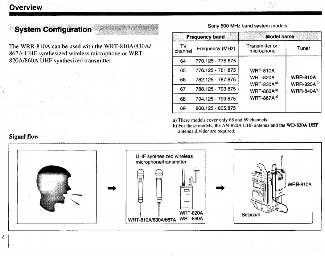
System
Configuration
ss
4
Wireless
Channels
Selectable
sn
5
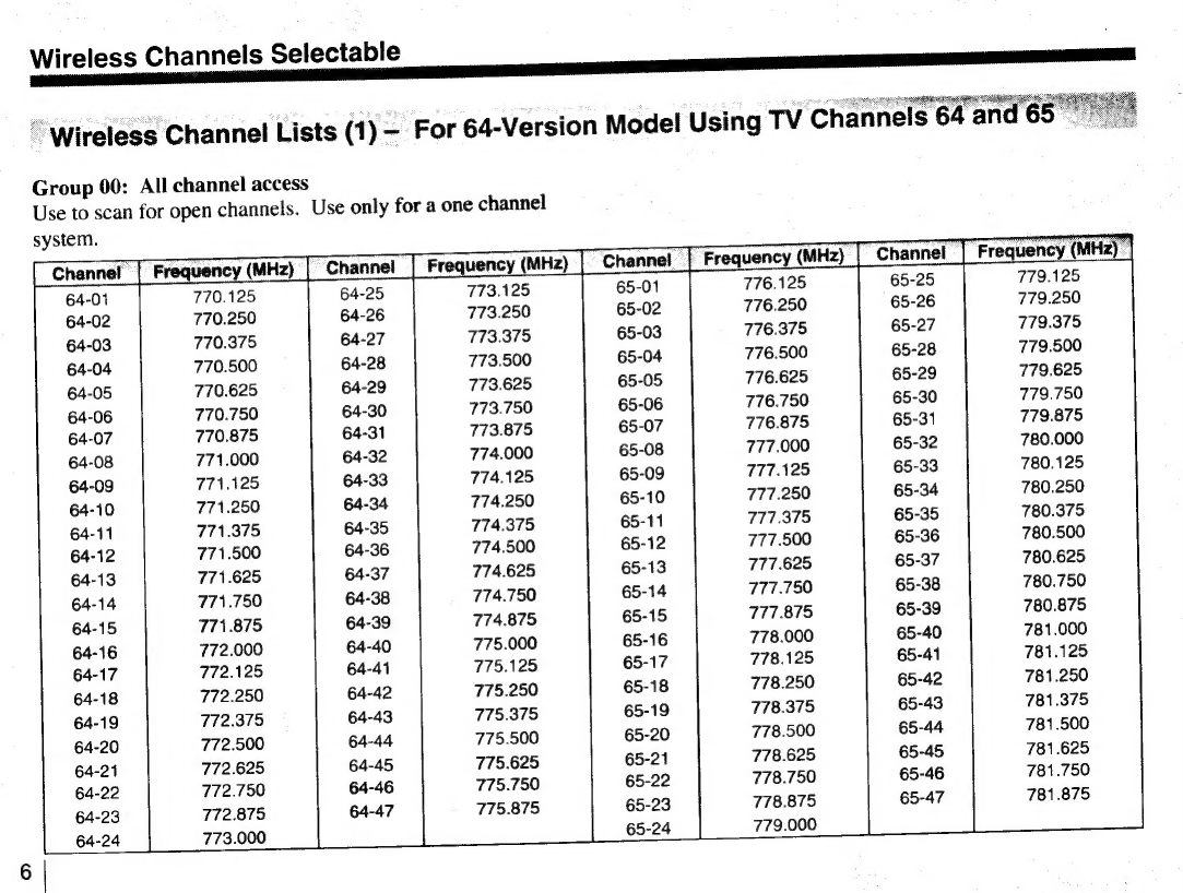
Wireless
Channel
Lists
(1)
—
For
64-Version
Model
Using
TV
Channels
64
and
65...
6
Wireless
Channel
Lists
(2)
—
For
66-Version
Model
Using
TV
Channels
66
and
67...
8
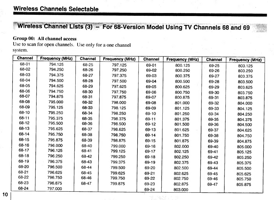
Wireless
Channel
Lists
(3)
—
For
68-Version
Model
Using
TV
Channels
68
and
69
occ
cscssessereescerees
10
Precautions
.....ccccsccsscssrseceseees
skecebeeees
restes
dre
jsesavevesees
12
Parts
Identification
...........cccsccscsseees
sdegdsndesdaedstaavasoiedves
13
Power
Supply
ss
EE
E
se
LS
Wireless
Channel
Selection
ss
sacs
LO
Connections
......secsresesssssessscssccsccssscsescesooes
A
PTE
18
Antenna
and
Output
Cable
sd
etes
dt
EEE
18
Connection
to
the
Betacam
...........cccsssssosessesnsnseesessees
19
Error
Messages
.seseeenenenensnnnnsss
20
Specifications
ses
21