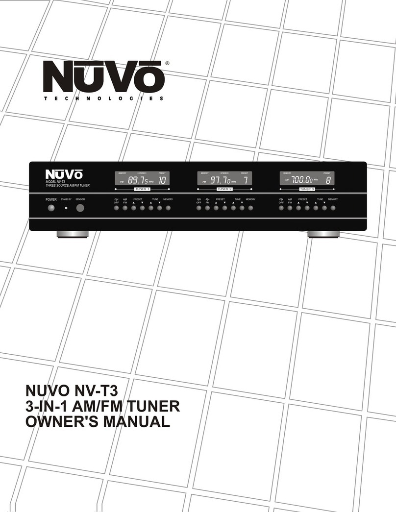
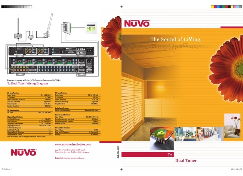
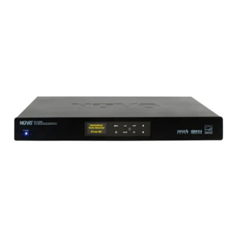
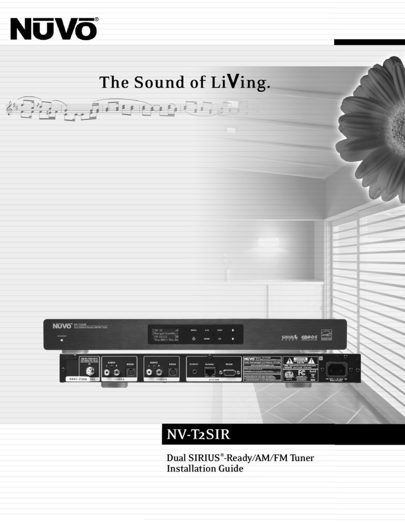
Nuvo NV-T2FAM-EX User manual

NV-T2FAM-EX
Dual AM/FM Tuner
Installation Guide


ENGLISH
Danger
Exposure to extremely high noise levels may cause a permanent
hearing loss. Individuals vary considerably to noise induced hearing
loss but nearly everyone will lose some hearing if exposed to sufficiently
intense noise for a sufficient time. The U.S. Government's
Occupational Safety and Health Administration (OSHA) has specified
the following permissible noise level exposures:
According to OSHA, any exposure in the above permissible limits could
result in some hearing loss. Ear plugs or protectors in the ear canal or over
the ears must be worn when operating this amplification system in order to
prevent a permanent hearing loss. If exposure in excess of the limits as
put forth above, to insure against potentially harmful exposure to high
sound pressure levels, it is recommended that all persons exposed to
equipment capable of inducing high sound pressure levels, such as this
amplification system, be protected by hearing protectors while this unit is in
operation.
DURATION PER DAY (HOURS) 8 6 4 3 2 1
SOUND LEVEL (dB) 90 93 95 97 100 103
THIS SYMBOL IS INTENDED TO ALERT THE USER TO THE PRESENCE
OF NON-INSULATED "DANGEROUS VOLTAGE" WITHIN THE
PRODUCT'S ENCLOSURE THAT MAY BE OF SUFFICIENT MAGNITUDE
TO CONSTITUTE A RISK OF ELECTRIC SHOCK TO PERSONS.
THIS SYMBOL IS INTENDED TOALERT THE USER TO THE PRESENCE
OF IMPORTANT OPERATING AND MAINTENANCE (SERVICING)
INSTRUCTIONS IN THE LITERATURE ACCOMPANYING THE UNIT.
1. Read all safety and operating instructions before using this
product.
2. All safety and operating instructions should be kept for future
reference.
3. Read and understand all warnings listed on the operating
instructions.
4 . Follow all operating instructions to operate this product.
5. This product should not be used near water, i.e. Bathtub,
sink,swimming pool, wet basement, etc.
6. Only use dry cloth to clean this product.
7. Do not block any ventilation openings, It should not be placed flat
against a wall or placed in a built-in enclosure that will impede the
flow of cooling air.
8. Do not install this product near any heat sources ;such
as,radiators, heat registers, stove or other apparatus (including
heat producing amplifiers) that produce heat.
9. Do not defeat the safety purpose of the polarized or grounding-
type plug. A polarized plug has two blades with one wider than the
0ther.A grounding-type plug has two blades and a third grounding
prong. The wide blade or the third prong are provided for your
safety If the provided plug does not fit into your outlet, consult an
electrician for replacement of the obsolete outlet.
10. Protect the power cord being walked on or pinched, particularly at
Plugs, convenience receptacles and the point where they exit
from the apparatus. Do not break the ground pin of the power
supply cord.
11 . Only use attachments specified by the manufacturer.
12. Use only with the cart, stand, tripod, bracket, or table specified by
the manufacturer or sold with the apparatus. When a cart is used,
use caution when moving cart/apparatus combination to avoid
injury from tip-over.
13. Unplug this apparatus during lightning storms or when unused for
long periods of time.
14. Care should be taken so that objects do not fall and liquids are
not spilled into the unit through the ventilation ports or any other
openings.
15. Refer all servicing to qualified service personnel. Servicing is
required when the apparatus has been damaged in any way;
such as, power-supply cord or plug is damaged, liquid has been
spilled or objects have fallen into the apparatus, the apparatus
has been exposed to rain or moisture, does not operate normally
or has been dropped.
16. WARNING: To reduce the risk of fire or electric shock, do not
expose this apparatus to rain or moisture.
IMPORTANT SAFETY INSTRUCTIONS
RISK OF ELECTRIC SHOCK
DO NOT OPEN
CAUTION: TO REDUCE THE RISK OF ELECTRIC SHOCK, DO
NOT REMOVE CHASSIS. NO USER-SERVICEABLE
PARTS INSIDE. REFER SERVICING TO QUALIFIED
SERVICE PERSONNEL.
AVIS: RISQUE DE CHOC ELECTRIQUE-NE PAS OUVRIR.
CAUTION
APPARATUS SHALL NOT BE EXPOSED TO DRIPPING OR SPLASHING
AND THAT NO OBJECTS FILLED WITH LIQUIDS, SUCH AS VASES,
SHALL BE PLACED ON THE APPARATUS.

FRENCH
DURE EN HEURES PAR JOUR 8 6 4 3 2 1
INIVEAU SONORE CONTINU EN dB 90 93 95 97 100 103
Danger
L‘exposition a des niveaux eleves de bruit peut provoquer une perte
permanente de l’audition, Chaque organisme humain reagit
differemment quant a la perte de l’audition, mais quasiment tout le
monde subit une diminution de I’acuite auditive lors d’une exposition
suffisamment longue au bruit intense. Les autorites competentes en
reglementation de bruit ont defini les expositions tolerees aux niveaux
de bruits:
Selon les autorites, toute exposition dans les limites citees ci-dessus,
peuvent provoquer certaines pertes d’audition. Des bouchons ou
protections dans l’appareil auditif ou sur l’oreille doivent etre portes lors
de l’utilisation de ce systeme d’amplification afin de prevenir le risque
de perte permanente de l’audition, Dans le cas d’expositions
superieures aux limites precitees il est recommande, afin de se
premunir contre les expositions aux pressions acoustiquese I evees
potentielIement dangeure u ses, aux personnes exposees aux
equipements capables de delivrer de telles puissances, tels ce
systeme d’amplification en fonctionnement, de proteger l’appareil
auditif.
ATTENTION: AFIN DE LlMlTER LE RISQUE DE CHO ELECTR/QUE, NE
PAS ENLEVER LE CHASSIS. NE CONTIENT PAS DE
PIECES POUVANT ETRE REPAREE PAR L’UTILISATEUR.
CONFER LE SERVICE APRES-VENTE AUX
REPARATEURS
ATTENTION
RISQUE DE CHOC ELECTRIQUE
NE PAS OUVRIR.
CE SYMBOLE A POUR BUT D'AVERTIR L'UTILISATEUR DE LAPRESENCE
DE VOLTAGE DANGEREUX NON-ISOLE A L'INTERIEUR DE CE PRODUIT
QUI PEUT ETRE DE PUISSANCE SUFFISAMMENT IMPORTANTE POUR
PROVOQUER UN CHOC ELECTRIQUE AUX PERSONNES.
CE SYMBOLE A POUR BUT D'AVERTIR L'UTILISATEUR DE LAPRESENCE
D'INSTRUCTIONS D'UTILISATION ET DE MAINTENANCE DANS LES
DOCUMENTS FOURNIS AVEC CE PRODUIT.
IMPORTANTES INSTRUCTIONS DE SECURITE
1. Lire avec attention toutes les recommandations et précautions
d'emploi avant d'utiliser ce produit.
2. Toutes les recommandations et précautions d'emploi doivent être
conservées afin de pouvoir s'y reporter si nécessaire.
3. Lire et comprendre tous les avertissements énumérés dans les
précautions d'emploi.
4. Suivre toutes les précautions d'emploi pour utiliser ce produit.
5. Ce produit ne doit pas être utilisé près d'eau, comme par exemple
baignoires, éviers, piscine, sous-sol humides ... Etc.
6. Utiliser exclusivement un chiffon sec pour nettoyer ce produit.
7. Ne bloquér aucune ouverture de ventilation. Ne pas placer le
produit tout contre un mur ou dans une enceinte fernée, cela
gênerait le flux d'air nécessaire au refroidissement.
8. Ne pas placer le produit près de toute source de chaeur telle que
radiateurs, arrivées d'air chaud, fourneaux ou autres appareils
générant de la chaleur (incluant les amplificateurs producteurs
de chaleur) .
9. Ne pas négliger la sécurité que procure un branchement polarisé
ou avec raccordement à la terre, Un branchement polarisé
comprend deux fiches dont l'une est plus large que l'autre. Un
branchement à la terre comprend deux fiches plus une troisième
reliée à la terre. Si la fiche secteur fournie ne s'insert pas dans
votre prise de courant. consulter un 'électricien afin de remplacer
votre prise obsolète.
10. Protéger le cordon d'alimentation de tout écrasement ou
pincement, particulièrement au niveau des fiches, des
réceptacles utilisés et à l'endroit de sortie de l'appareil. Ne pas
casser la fiche de terre du cordon d'alimentation.
11. Utiliser uniquement les accessoires spécifiés par le constructeur.
12. Utiliser uniquement avec le chariot de transport, le support, le
trépied, la console ou la table spécifiés par le constructeur ou
vendus avec l'appareil. Lors de l'utilisation d'un chariot, bouger
avec précaution l'ensemble chariotlappareil afin d'éviter les
dommages d'un renversement.
13 Débrancher cet appareil lors d'orages ou s'il n'est pas utilisé
pendant une longue période.
14. Des précautions doivent être prises afin qu'aucun objet ne tombe
et qu'aucun liquide ne se répande à l'intérieur de l'appareil par
les orifics de ventilation ou n'importe quelle autre ouverture.
15. Pour toutes interventions techniques s'adresser à un technicien
qualifié.L'intervention technique est nécessaire lorsque l'appareil
a été endommagé de n'importe quelle façon, comme par
exemple si le cordon secteur ou sa fiche sont détériorés,si du
liquide a coulé ou si des objets sont tombés à l'intérieur de
l'apparei1,si l'appareil a été exposé à la pluie ou à l'humidité, s'il
ne fonctionne pas normalement ou s'il est tombé.
16. ATTENTI0N:Pour réduire le risque d'incendie ou de choc
electrique ne pas exposer l'appareil à la pluie ou à l'humidité.
AFIN DE REDUIRE LES RISQUÉ D'INCENDIE ET DE DECHARGE
ELECTRIQUE, NE PAS EXPOSER CET APPAREIL A LAPLUIE OU A
L'HUMIDITE.

GROUND
CLAMPS
ELECTRIC
SERVICE
ENTRANCE
ANTENNA
DISCHARGE UNIT
NEC SECTION
810-20
GROUNDING
CONDUCTORS
GROUND CLAMPS
POWER SERVICE
GROUPING ELECTRODE
SYSTEM NEC ART 250
PART H
NEC NATIONAL ELECTRICAL CODE
ANTENNA
LEAD-IN
WIRE

Introduction
CongratulationsonyourpurchaseoftheNuVoT2DualTuner.Enjoyingbroadcastmusicthroughoutthehomehasmovedintothe
st
21centurywithNuVo’sT2DualTunersolutions.TheincludedactiveAM/FMantennaprovidesaclearprecisesignaltothehome.
TheT2’sinternalNuVoNetcommunicationallowsforveryuniqueandcompletefeedbacktoalloftheNuVoControlPadsincluding
RDS(RadioDataService)artistandsonginformation.
WithNuVo,broadcastmusichasneverbeenbetter.
1
Table of Contents:
Basic Features
I. Installing the T2FAM-EX in the Home
II. T2FAM-EX Front Panel Menu
T2FAM-EX Quick Setup Guide for Use with NuVoNet page2
FrontPanel page4
BackPanel page5
NV-T2RC4RemoteControl page6
ConnectingtheAudioOutputs page7
SettingtheAudioOutputsforNuVoNetor
Standaloneuse page7
AM/FMAntennaInstallation page8
ConnectingforNuVoNetUse page8
IRControloftheT2FAM-EX page8
RS232SerialControl page9
Bands page9
T2FAM-EXOptions page9
EditPresets page9
TuningMode page10
T2FAM-EXSettings page10
OperatingMode page10
EnabledBands page10
Tuning page10
Diagnostics page11
ResetMemory page11
III. NuVoNet Control of the T2FAM-EX
IV. Using the T2 Configurator Software
Advanced Settings
TuningUpandDown page12
ChangingBands page12
TuningModes page12
SelectingTunerAorB page12
ControlPadMainMenu page13
1.0Start page15
2.0Config page15
3.0Presets page17
4.0AdvancedConfig page18
5.0UpdateSystem page20
NV-T2FAM-EX Specifications page21

2
T2FAM-EX Quick Setup Guide for Use With NuVoNet
TheT2FAM-EXDualTuneristheperfectbroadcastmusicsolutionforwhole-homeaudio.TheinternalNuVoNetcapabilityofthe
T2FAM-EXallowsittoeasilycommunicateinrealtimewiththeNuVoGrandConcertoandEssentiaE6GControlPads.Thefollowing
isastep-by-stepguideforsettingupandinstallingtheT2FAM-EXforusewiththeGrandConcertoandEssentiaNuVoNetSuites.
Step 1: UponunpackingyourT2FAM-EXTuner,establishwhataudioinputs,1-6,theT2’sAandBaudiooutputswillrepresent.Plug
theT2intoanACpowersource.
Step 2: AttachtheaudiooutputsAandBoftheTunertotheappropriatenumberedinputsontheGrandConcertoorEssentia
System.
Step 3: ConnecttheCAT5fromtheNuVoNetoutputontherearpaneloftheTunertooneoftheDeviceinputsontheGrandConcerto
EZPortortheEssentiaAllport.ThiswillenablecommunicationtotheSystem’sControlPads.NotethatasingleCAT5connection
providesinformationfrombothtunersAandB.AfinalCAT5ConnectionshouldthenbemadetotheNuVoNetCAT5inputonthe
backpaneloftheGrandConcertoorEssenitamainamplifierfortheNuVoNetRJ45ontheGrandConcertoEZPortortheEssentia
Allport.ThiscompletesthenecessaryconnectionfortheNuVoNetcommunication.
T2FAM-EX Wiring Diagram
072 8
303 3118
R
T
E
E
T
K
N
I
CM
Model NV-T 2FA M- EX
Dua l SIRIU S Ready AM /FM Tune r
www. nu vo tec hn ol ogi es .co m
NuVo Technol og ie s LLC Hebr on , KY US A•
CONF ORMS TO UL
STD. 6006 5 CERTIF IED
TO CAN /CSA STD .
C22. 2 No.6 0065:0 6
RS 232
SYST EM
ANTE NNA
IN NuVoNet
USE N V-T 2D AA WITH
OPT IO NA L NV-T 2FX C
AND SIR IU S ANTENN A
IR INPUT
L
AUDIO
R
TUNE R A
L
AUDI O
R
TUNE R B
RoHS
R
OUTPUT POWER OUTPUT POWER
20W/6OHM X2 20W/6OHM X2
SYS ON
EXT. MUTE
L
R
L
R
L
R
VARI AB LE
OUT PU T
FIX ED
OUT PU T
SUM1
3033 118
CUS
CON FORMS T O
UL ST D.65 00
CER TIFIE D TO
CAN /CSA S TD.E 6006 5
NuVo Tec hnolo gies C incin nati Oh io USA
FUS E:T5 A
120 V 60 Hz 50 0W
MODE L NV-I8 DM
SIX SO URCE EI GHT ZON E
AUDI O DISTR IBUTI ON SYST EM
www. nuvo tech nol ogie s.c om
OUTPUT POWER
OUTPUT POWER
OUTPUT POWER
20W/6OHM X2
20W/6OHM X2
20W/6OHM X2
TIP =L
RIN G= R
VARI AB LE
OUT PU T
FIX ED
OUT PU T
TIP=L
RIN G= R
VARI AB LE
OUT PU T
FIX ED
OUT PU T
TIP=L
RIN G= R
VARI AB LE
OUT PU T
FIX ED
OUT PU T
TIP=L
RIN G= R
VARI AB LE
OUT PU T
FIX ED
OUT PU T
TIP=L
RIN G= R
VARI AB LE
OUT PU T
VARI AB LE
OUT PU T
FIX ED
OUT PU T
FIX ED
OUT PU T
TIP=L
RIN G= R
TIP=L
RIN G= R
1 2 3 4 5 6
1 2 3 4 5 6
2 3 41 2 3
RS-232
CON NECT TO
NV-I 8X
USE N V-SLC1
CAB LE
CON NECT TO
NV-I 8X
USE N V-SLC1
CAB LE
CON NECT TO
NV-I 8E ZP1
USE N V-NC1
CAB LE
USE CNLY WITH 250V FUSE
456SUM2
5 6 7 8
OUTPUT POWER
20W/6OHM X2
ZONE 6ZO NE 6 ZONE 7 &8
SYSTEM
ZONE TRI GG ER O UTPUTS
SOUR CE L IN K
SOUR CE I NP UT S
ZONE 1
NETWOR K
EMITTE R OUTPUTS DIGITAL LINK
ZONE 3 ZONE 4 ZONE 5
ZONE 2 PROG RA M
6
45
31
2
SOURCE STATUS I NP UT S
1
MENU OK
Modern Rock
Drift-Follow Th
Living For
AM/FM 3:09 pm
Diagram shown using the Grand Concerto System
Conc erto EZ Po rt
Mode l NV-I8GE ZP
Device 2 Device 3
Device 4 Device 5 De vice 6
Conn ect to
NV-I8 GM
www.nuv ote ch no log ies .co m
NuVo Techno logies LL C Hebr on, Kentu cky US A
Device 1

3
Step 4: CompletetheantennaconnectiononthebackpaneloftheTunerusingstandardRG6coaxialcable.Quadshieldedcableis
recommended.Whentheantennaisconnected,theTunerwillbeginreceivingasignalforbothTunersAandB.
Step 5: WhentheTunerispluggedintoanACpowersourcethefrontpaneldisplaywillmovethroughabootprocedure.Whenthis
procedureiscompleteamessage, UninitializedStateDetected willappear.
Step 6: Followingthepromptfromthedisplay,touchtheOKbuttonontheTuner’sfrontpanelcontrol.Thiswilldisplayaregional
tuningselection,USAandCanada,WesternEurope,Australia,andNewZealand.MaketoappropriateselectiontomatchtheTuner s
geographiclocation.
Step 7: TouchingOKonthefrontpanelcontrolswillpromptasecondscreenonthedisplay.Thiswillread,Set Tuner A Mode,
Standalone, Source 1, Source 2, Source 3, Source 4, Source 5, and Source 6. Thetopselection,Standalone, willbehighlighted.This
choiceisusedforanypurposethatisnotNuVoNetcommunication.Usingthedownarrowonthefarrightofthefrontpanel
controls,scrolltothedesiredsourceinputnumber,andtouchOKtoselect.ThedisplaywillautomaticallygotoTunerBsetup.
RepeatthestepsforsettingTunerA.IfNuVoNetisnotconnectedorallavailablesourceshavebeenassigned,thenthesource
selectionswillbegrayedout.
Step 8: Whenthedesiredsourcenumberisselected,thedisplaywillreturntothefirstscreen.BothoutputsAandBwilldisplay
thelowestAMbandfrequencybydefault.AtthispointfulltuningcapabilitycanbedonefromtheTuner’sfrontpanel,oran
addressedNuVoControlPad.
Step 9: WhenbothTuneroutputsareset,makesurethe NuVoNet CAT5connectionbetweentheTuner sbackpanelandthe
systemEZPortiscomplete.
TheT2FAM-EXTunerisnowreadyforNuVoNetcommunicationwitheithertheGrandConcertoorEssentiaE6Gdistributedaudio
systems.
PleaseseethecompleteinstallationguideforunderstandingthefulluseofyourT2FAM-EXTuner.

4
Front Panel Features
1. Standby: ThisblueLEDwilllightwhentheT2FAMispluggedintoanACpoweroutlet.
2. Tuner Highlight: ThishighlightbarshiftsbetweenthetunerAandBdisplaytoindicatewhichtunerisbeingcontrolled.
3. Broadcast Band Display: Thislineofthefrontpaneldisplayshowstheselectedbroadcastbandandfrequency.Thebands
availableareFMandDAB.
4. Metadata Display: ThislineofthedisplayscrollsRDS,RadioDataService,informationforFMbroadcast.
5. Preset Number: TheT2FAMfeaturesupto5banksof20presetseach.Thisindicatesthenumberofthepresetbankandthe
selectedpreset.
6. Antenna Signal: Thelevelofsignallevelisindicatedwithuptofivebars,fivebeingthebest.WhenlisteningtoFM,fullstereo
receptionisindicatedwithanabbreviatedST.
7. Menu: ThiscapacitivetouchpanelallowsfrontaccesstotheT2FAM’scontrolsaswellaspresetlisteningselectionsand
tuningparameters.
8. Power: Thisbuttonturnsthepowerforthefrontpaneloffwhentapped,andcausesasoftrebootoftheoperatingsystemwhen
itisheldfor3seconds.
9. A/B: BytappingtheA/Bbutton,thehighlightedtuneroutputcontroltogglesbetweenAandB.
10. Band: TheBandbuttontogglesbetweenAMandFMlistening.
11. IR Window: TheT2FAM-EXcanbecontrolledviaIRthroughitsfrontpanelIRreceiver.
12. OK: OkinitiatesahighlightedMenuchoice.
13. Disp: ThisbuttonisonlyactiveforSIRIUSSatelliteradio.ItdoesnotfunctionontheT2FAMTuner.
14. Up and Down Arrows: Thesearrowbuttonsprovidemultiplefunctionsdependingonthemodeofthetuner.Innormal
operationtheyinitiatetuningupanddownthroughtheselectedband.Wheninmenumodetheyscroll
upanddownthroughthemenuchoices.
MENU
BAND OK
A/B
DISP
NV-T2FAM-EX
Dual AM/FM Tuner
STANDBY
RADIO DATASYSTEM
AM 550
FM 103.5
Ticket To Ride
P103
P104 ST
1 4
5
6
7
8
9
10
12
13
14
2311

0728
303311 8
R
T
E
E
T
K
N
I
CM
Mode l NV-T2FAM- EX
Dual SIRIUS Ready AM/FM Tun er
www.n uv ot ec hn ol og ie s. co m
NuVo Tech nologies LL C H eb ron, KY USA•
CON FORMS TO U L
STD .6006 5 CERTI FIED
TO CA N/CSA ST D.
C22 .2 No.6 0065: 06
RS 232
SYSTEM
ANTENNA
IN NuVoNet
USE NV-T2FAA
ANTENNA
IR INP UT
L
AUDIO
R
TUNER A
L
AUDIO
R
TUNER B
RoHS
13456
2
Back Panel Features
1.Antenna Input: Thissingle F connectoristhecoaxialcableconnectionbetweentheT2FAM-EXandtheincludedNV-T2FAA
AM/FMantenna.
2.Audio Output: TheaudiobroadcastforAMandFMreceivedbytheTunermoduleisavailablethroughthisstereoRCAoutput.
TunerAandBofferindependentaudiooutputsforusewiththeNuVoaudiosystemsorthird
partyreceiversandamplifiers.
3.IR Input: TheT2FAM-EXoffersasinglestereomini,3.5mm,connectionforindependentIRcontrolofbothtunersAandB.
4.NuVoNet: ThissingleCAT5connectionprovidesfullNuVoNetcommunicationforbothtunersAandBtotheNuVoGrandConcerto
andEssentiaE6Gaudiodistributionsystems.ThisconnectionismadeattheGrandConcertoEZPortortheEssentia
E6GAllport.
5.RS232: ThisDB99-pinconnectorisusedforconfigurationprogramming(seeSection IV. Using the Tuner Configurator Software,
pg.15)andbidirectionalserialcontrolfromathirdpartyhomeautomationcontroller.
6.AC Power: TheT2FAM-EXisdesignedtoplugintoanyACpowersource.Thedigitalswitchingpowersupplyallowsthetunerto
respondtoanyworldwidevoltage.
5

123
456
7 8 9
0OK
AM
FM
DAB SAT
DISP
BAND
PWR A/B
PRE
T2 Tuner
NV-T2RC4
REMOTE CONTROL
TUNER
1
2
3
4
5
6
7
8
9
10
11
12
13
P
C
P
C
TUNE
NV-T2RC4 Remote Control
1.Power: Thepowerbuttonturnstheselectedtuneronandoff.
2.Tune Buttons: ThesebuttonsaretheequivalentofusingtheUpandDownarrowsonthefrontpaneloftheT2FAM-EXto
tune.
3.Band: Thisbuttontogglesthroughthetuner savailablebroadcastbands.
4.Seek Up and Down: TheseekbuttonswilltunetothenextavailablestationwiththerequiredsignalstrengthforAMand
FMuse.ThesignalthresholdcanbeadjustedhigherorlowerusingtheTunerConfiguratorsoftware
(seeSection IV. Using the Tuner Configurator Software, pg.18),orthroughtheadvancedmenuoptions
onthefrontpanel(seeSection II. T2FAM-EX Front Panel Menu, Seek Thesholds, pg.11).
5.Preset Tune: Thesebuttonsstepthroughtheassignedpresets.TheT2FAM-EXiscapableof5banksof20presets.
6.Category Tune: CategoryTuneisnotimplementedonthismodel.
7.Pre: Thisbuttonisusedtoestablishapresetbankandpresetnumberforthefrequencybeingdisplayedontheselected
tuner.
8.Tuner A & B LED: ThisLEDglowsredwhenTunerAisselectedandgreenwhenTunerBisselected.ThisLEDglowsonly
momentarilywhenabuttonispushed.
9.A/B: ThisbuttontogglesbetweenTunerAandTunerBoperation.
10.Disp: ThisbuttonfunctionsonlyforNorthAmericansatelliteradiouse.
11.Numeric Buttons: Thesebuttons(0-9)areusedtoaccessaspecificstationfrequency.
12.OK: ThisisaselectbuttonusedforsavingpresetsorenteringanAMorFMfrequency.
13.Source Buttons: ThesefourbuttonsareadirectselectforthetuningbandsavailablethroughtheT2Tuners.Actual
functionalitydependsonthemodeltunerbeingcontrolled.
6

7
I. Installing the T2FAM-EX in the Home
Connecting the Audio Outputs (Fig. 1)
TheT2FAM-EXhastwoindependentaudiooutputslabeledA
andB.ThesearestandardstereoRCAconnectionsandcanbe
connectedtoanydevicedesignedtoreceiveananalogstereo
audiosignal.
Setting the Audio Outputs for NuVoNet or Standalone use
(Fig. 2)
TheoutputsAandBareindividuallysetfromthefrontpanel
displayoftheT2FAM-EX.Whenthetunerisinitiallyplugged
intoanACpowersource,ashortsetupwizardwillappearon
thedisplay.Amessage, UninitializedStateDetected(Press
OK) willappear.WhenOKispressed,thepromptistoselecta
regionaltuningstandard.ThechoicesareUSA/Canada,
WesternEurope,Australia,andNewZealand.UsetheUpand
Downarrowstohighlighttheappropriatechoiceandtouchthe
OKbuttontoselect.Onceregionaltuninghasbeenselected,
thedisplaywillpromptfortheuseofeachoutputAandB.
+OutputA willhighlightautomatically.UsingtheUpand
Downarrowsonthefrontpanel,movethehighlighttothe
appropriateuseofthetuneroutputandtouchOK.Thechoices
areStand Alone, Source 1, Source 2, Source 3, Source 4, Source
5, and Source 6. ForanyuseotherthanwiththeEssentiaE6G
orGrandConcertoSystems,selectStand-alone.Thiswill
requireIRorserialcontroloftheT2FAM-EX’sfunctions.
HighlightingtheappropriateSourcenumberinputfortheNuVo
systemandtouchingtheOKbuttonsetsNuVoNet
communication.OnceOutputAisset,thehighlightwillmove
toOutputB.Foroperation,bothoutputsAandBmustbesetas
StandAloneorasaNuVoNetSource.
WhentheTuner’soutputsareset,theywillreturntoAM530,or
theminimumAMbandsettingfortheselectedregionaltuning
parameters.AtthispointtheT2FAM-EXisreadyforeither
NuVoNetcommunicationorstandaloneuse,dependingonthe
settingmadeforbothoutputs.
ANTENNA
IN
USE N V-T2FAA
ANTENNA
L
AUDIO
R
TUNER A
L
AUDIO
R
TUNER B
SOURC E LI NK
L
R
L
R
L
R
SOURC E IN PUT S
TIP =L
RIN G=R
ZONE 2
VARI ABLE
OUT PUT
FIX ED
OUT PUT
TIP= L
RIN G=R
VARI ABLE
OUT PUT
FIX ED
OUT PUT
TIP= L
RIN G=R
VARIA BLE
OUT PUT
FIX ED
OUT PUT
TIP= L
RIN G=R
1 2 3 4 5 6
1 2 3 4 5 6
1 2 3
4
CON NECT TO
NV-I 8X
USE N V-SLC1
CAB LE
56
ZON E 1
VARI ABLE
OUT PUT
FIX ED
OUT PUT
S PEAK ER
40W /6 OHMS X 2
LEF T RIG HT
ZONE 3 ZON E 4
SOURC E STATU S
S PEAK ER
40W /6 OHMS X 2
LEF T RIG HT
S PEAK ER
40W /6 OHMS X 2
LEF T RIG HT
S PEAK ER
40W /6 OHMS X 2
LEF T RIG HT
Fig. 1
Fig. 2
MENU
BAND OK
A/B
DISP
Uninitialized
State Detected
(Press OK)
MENU
BAND OK
A/B
DISP
Regional Setup
US and Canada
Western Europe
Australia
MENU
BAND OK
A/B
DISP
Set TunerA Mode
Standalone
Source 1
Source 2

8
AM/FM Antenna Installation (Fig. 3)
TheT2FAM-EXisshippedwiththeNV-T2FAAactiveAM/FM
antenna.Theantennaisdesignedtoworkactivelywiththe
tunerusingstandard75-ohmcoaxialcable.Quad-shielded
cableisrecommendedforthispurpose.Theadvantageofthe
activeantennatechnologyistheremotelocationcapability,up
to200feetfromtheT2FAM-EXlocationwithouttheneedfor
anexternalpowersupply.Theterminationattheantennaand
tunerisastandard F styleconnector.Nosoftware
applicationorconfigurationisnecessarybeyondmakingthe
cableconnectionateachend.
Note, for best results, the T2FAA antenna should be located as
high as possible, either in an attic or outside. If you choose to
use a third party antenna, other than the T2FAA, you must use
the forced off setting from the menu to allow the signal to pass
through to the T2FAM-EX, (see Section II. T2FAM-EX Front Panel
Menu, Antenna Power, pg. 11).
Connecting for NuVoNet Use (Fig. 4)
OnceaudiooutputsAandBaresetforNuVoNet,theT2FAM-EX
isreadytocommunicateinrealtimewiththeGrandConcerto
orEssentiaE6Gaudiodistributionsystems.Tocompletethe
connection,allthatisnecessaryisasingleCAT5cablefromthe
NuVoNetoutputontheT2FAM-EX’sbackpaneltooneofthe
DeviceinputsoneithertheGrandConcertoEZPortorthe
EssentiaE6GAllport.SincetheoutputsoftheTunermustbe
setasaspecificsourcenumberinputforNuVoNet
communication,thenumberoftheDeviceconnectionusedis
irrelevanttothesystem’soperation.Oncetheconnectionis
complete,thetunerisreadytofullycommunicatewith
NuVoNet.
IR Control of the T2FAM-EX (Fig. 5)
TheT2FAM-EXcanbeusedwithoutNuVoNetasastandalone
AM/FMtuner.Itisnecessarytosettheaudiooutputsat
Standalone forIRcontroltobeactive(seeSection I. Setting
the Audio Outputs for NuVoNet or Standalone Use, pg.7).
Fig. 3
Fig. 4
MENU
OK
Jozef Kossovit
SIR
SR 86 (P101)
SIRIUS Pops
3:09 PM
Hungaria
0728
3033 118
E
R
T
E
T
K
N
I
CM
Mod el NV- T2FA M-E X
Dual A M/FM Tune r
www. nuvo tech no logi es.c om
NuVo Tec hnolog ies LL C Hebr on, KY U SA•
CONF ORMS TO UL
STD. 60065 CE RTIF IED
TO CAN/C SA STD.
C22. 2 No.600 65:0 6
RS 23 2
SYSTE M
NuVoN et
IR IN PUT
RoHS
The NuVo active
antenna can be located up
to 200 feet from the
T2FAM-EX Tuner.
ANTE NNA
IN
USE N V-T2FAA
ANT EN NA
L
AUDIO
R
TUNE R A
SIRIUS L
AUDIO
R
TUNE R B
SIRIUS

9
OncetheaudiooutputsaresetatStandalone,theT2FAM-EX
offersthreemethodsforIRcontrol.OneistotaketheIR
outputofyourcontroldeviceusingamono3.5mmpatchcable
intotheDirectIRinputonthebackpaneloftheT2FAM-EX.
TunersAandBfeaturediscretecommands,allowingboth
tunerstobecontrolledindependentlyfromoneinput.The
secondmethodforIRcontrolistoattachanIRemitteroverthe
IRreceiveronthefrontpanel,andthethirdmethodistoaim
theremotecontrolattheIRreceiverlocatedonthefront
panel.
RS232 Serial Control
TheT2FAM-EXfeaturesabidirectionalDB9portforserial
control.Thisenablesthetunertobecontrolledviaathirdparty
homeautomationsystemandwillinturnissuepresentstate
commandsbacktothecontroller.Potentially,allaspectsof
NuVoNetcommunicationcanbeemulatedusingtheserial
controlcapability.Thenecessaryprotocolforserialusecanbe
downloadedfromtheNuVowebsiteProZoneat
www.nuvotechnologies.com/prozone.

10
Delete Preset, whichwillerasethehighlightedpreset
fromthelist;Add to Favorites placesthehighlighted
presetintotheFavoritesmenuavailableateach
ControlPad;Move Up andMove Down movethe
highlightedpresetupordownwithinthelistof
presets;Move to Top andMove to Bottom placethe
highlightedpresetinthenumber1positionortothe
lastavailableposition.
Tuning Mode (Fig. 10): TuningModehasfourchoices
thatsetdefaultsforthewayinwhichtheT2FAM-EX
willtunethroughchannelsorfrequencies.
Seek Tune: SeekTunesearchesforstrong
frequenciesinAM/FMbandsandwillstopat
thenextfrequencythatmeetsthesettuning
parameters.Thismenuoptionturnsseekon
oroff.WhenSeekTuneisturnedoff,Step
Tuneisthedefault.
Preset Tune: Whenturnedon,thePresetTune
modewillonlystopatchannelsor
frequenciesthathavebeensavedaspresets.
Fig. 10
Tuning Mode
Seek Tune
Preset Tune
T2FAM-EX Settings (Fig. 11)
Thereareseveraloperationaldefaultsthataresetinthismenu
choice:
Operating Mode (Fig. 12): Thiswilldisplaytheset
choiceforeachtuneroutputAandBwithacheck
mark.ThechoicesareStandalone, Source 1, Source 2,
Source 3, Source 4, Source 5, andSource 6. Here,the
sourcenumberorstandalonecanbechangedfromthe
initialpoweronsetting.UsedNuVoNetsourceswillbe
grayedout.
Enabled Bands: Broadcastbandsassociatedwitheach
tunercanbeturnedoffhere.Thisisusefulespecially
forAMwhereanacceptableAMsignalisnotpossible.
Fig. 11
Fig. 12
T2FAM Settings
Operating Mod
Enabled Bands
Tuning
Operating Mode
Tuner A
Tuner B
Set Tuner A Mo
Standalone
Source 1
Source 2
Tuning: Therearefoursub-menusthatsetdefault
tuningparametersfortheT2FAM-EX:
Fine Tuning: Thisreducesthefrequencystep
to50kHzinFMand1kHzinAM.Withtoday’s
digitaltunersthisfeatureisrarelyused.
Regional Setup: RegionalSetupsetsthe
defaulttuningstandardforfourregionsof
theworld.ThechoicesareUS/Canada,
WesternEurope,Australia,andNewZealand.
Customisgrayedout.Thismustbesetusing
theConfiguratorSoftwarediscussedlaterin
thismanual.

11
Fig. 13
Seek Thresholds
AM Threshold
FM Threshold
AM Threshold
Level 1
Level 2
Level 3
Diagnostics (Fig. 14): SignalstrengthforAM,FMand
receptionandthecurrentfirmwareversionnumber
areprovidedintheDiagnosticsmenu.
Version: ThisdisplaystheT2FAM-EX’s
currentfirmwareversion.Upgradedversions
arepostedontheNuVowebsiteProZoneand
areloadedontotheTunerbydownloadinga
newconfigurationfromtheTuner
ConfiguratorsoftwarethroughtheRS232
port.
AM/FM Signal Strength (Fig. 15): This
displaystwolevelsfortunersAandB.RSSI,
receivedsignalstrengthindicator,isa
measurementindBuV,andSNR,signalto
noise,ismeasuredindB.
Reset Memory (Fig. 16): Thisshouldbeusedonly
whenitisadvantageoustoremoveallsettingsfrom
thetuner.Choosingyestoresetmemoryreturnsthe
T2FAM-EXtoitsfactorydefault.
Fig. 14
Diagnostics
Version
Signal Streng..
Reset Memory
Seek Thresholds (Fig. 13): Therecognized
signallevelforAMandFMcanbesetinthis
menu.Therearethreedefaultlevelswith1
beingthelowest,requiringastrongersignal
toberecognizedand3beingthehighest,
requiringaweaktomoderatesignaltobe
recognized.Thedefaultis2,themiddlelevel.
Brightness: Brightnesssetstheoveralllevel
ofthedisplay.Therearesevendegreesof
brightnesstochoosefrom.
Antenna Power: Thechoiceshereare
Automatic, Forced ON andForced OFF.
Automatic isthedefaultandallowsthe
T2FAM-EXtoprovide5voltstotheattached
T2FAAactiveantenna.Thisisnecessaryfor
AMreception.Ininstanceswhereyouintend
onusingathirdpartyFMantenna,the
ForcedOFF choiceisnecessarytoblockDC
voltageneededforAMreception.Thisisa
nicefeaturethateliminatestheneedforan
externalDCblocker. ForcedON provides Fig. 15
Fig. 16
AM/FM Strength
RSSI: 60 dBuV
SNR: 31 dB
Are You Sure?
No
Yes

12
III. NuVoNet Control of the T2FAM-EX
NuVoNetallowstheGrandConcertoandEssentiaE6GControl
PadtocompletelycontroltheT2FAM-EXfunctionality.The
importantfeatureoftheControlPadisitsmulti-lineOLED,
(organiclightemittingdiode)display,whichgivecomplete
tunerfunctionfeedback.
Tuning Up and Down (Fig. 17)
TuningattheNuVoControlPadisaccomplishedbytouching
arrowforward>> orarrowback<<.Asingletouchadvancesone
stationfrequencybasedonthetuningmethodselected,anda
touchandholdwillrapidlychangethechannelorfrequency.
Changing Bands (Fig. 18)
Innormalplaymode,touchingthePlay/Pausebuttonchanges
thebroadcastband.ThiscanalsobedoneintheBandsmenu
selection.Ifabandhasbeenturnedoff,(seeSection II.
T2FAM-EX Front Panel Menu, T2FAM-EX Settings, Enabled
Bands, pg.10),onlytheenabledbandswillbepresent.
Tuning Modes
TheavailabletuningmodesareSeekandPresettune.Seekis
anAM/FMfunctionthatsearchesforstrongerfrequencies.
Presettunemovestothenextpresetinthelist.Touchingand
holdingthePlay/Pausebuttonadvancestothenexttuning
mode,seekorpreset.
Selecting Tuner A or B
Innormalplaymode,selectinganewsourceisdoneby
touchingtheOKbutton.Eachtouchwilladvancetothenext
source.Accessingthesourcescanalsobedonefromthe
SourcesmenuateachControlPad.
MENU
OK
Fly 92.9
FM
FM 92.9
3:15 PM
Change Tuner Bands
Fig. 17
Fig. 18
MENU
OK
drift
FM
KROCK 89.9 (P101)
3:09 PM
Follow the Day
Tuning Up and Down

13
Control Pad Main Menu (Fig. 19)
TouchingtheMenubuttontakestheControlPaddisplaytothe
MainMenuwheretheuserhasseveralcontrolchoices.Oncein
theControlPadMenu,thearrowUpandDownbuttonsmove
thehighlightupanddown.Whenthedesiredchoiceis
highlighted,touchtheOKbuttontoinitiatethecommand.
Favorites (Fig. 20): TheNuVoNetsystemplacesthe
top20presetsorplaylistsforeachsourceinone
alphabeticallist.Thisallowstheusertomakea
selectionwithouthavingtochoosethatsourcefirst.
Sources (Fig. 21): Sources1-6arelistedinthismenu
foreasyaccess.NuVoNetautomaticallyassignsthe
namesT2FAM-EX(A)andT2FAM-EX(B)whenthe
NuVoNetsourcenumberisestablishedattheTuner,
(seeSection I. Setting the Audio Outputs for NuVoNet
or Standalone use, pg.7).
Bands: Thisdisplaystheavailablebroadcastbandsfor
theselectedtuner.
Presets: Presetsonlyappearifchannelsor
frequencieshavebeensaved.TheT2FAM-EXallows5
banksof20presetseach.Thegroupsof20are
automaticallydefinedasMyPresets1,MyPresets2,
etc.,unlesstheyaregivenpresetgroupnamesinthe
TunerConfiguratorSoftware.Whenapresetischosen,
thefrontpanelwilldisplayitsbankandpreset
number.Forexample,P103notespresetbank1and
preset3of20total.
Main Menu
Favorites
Sources
T2FAM-EX Options
My Presets 1
Fig. 20
Fig. 21
Favorites
The Loft
700 WLW
KROCK 89.9
Sources
NV-T2FAM-EX (A)
NV-T2FAM-EX (B)
NV-M3 (A)
NV-M3 (B)
NV-M3 (C)
Cable
Fig. 19
MENU
OK
drift
FM
KROCK 89.9 (P101)
3:09 PM
Follow the Day
Menu Access
55 KRC
Oldies 91.9
My Presets 2
Adv. Zone Control
Setup

14
T2FAM-EX Options (Fig. 22): Tuningparametersfor
theT2FAM-EXareeasilysetfromanyControlPad
usingthismenu.Therearethreesub-menuchoices:
Edit Presets (Fig. 23): Thisallowstheuserto
establishthecurrentchannelorstation
frequencyasapreset.Themenuprovides
fivebanksof20presetseach.Choosinga
presetbankwillthengiveyoutheoptionof
savingthecurrentchannel.Toaddapresetto
favorites,highlightandselectanexisting
preset.Thiswillbringupasecondmenuwith
severalchoices.Delete Preset, willerasethe
highlightedpresetfromthelist.Add to
Favorites placesthehighlightedpresetinto
theFavoritesmenuavailableateachControl
Pad.Move Up andMove Down movethe
highlightedpresetupordownwithinthelist
ofpreset.Move to Top andMove to Bottom
placethehighlightedpresetinthenumber1
positionortothelastavailableposition.
Seek Tune: SelectingSeekTuneturnsthe
frequencyseekfunctiononandoff.When
checkmarked,seekisactive.Thisisan
AM/FMfunctionthatallowstheTunerto
searchwithintheselectedbanduntilastrong
signalisfound.Thelevelofsignalnecessary
fortheseekfunctioncanbesetwithinthe
T2FAM-EXmenu,(seeSection II. T2FAM-EX
Settings, Seek Threshold, pg.11).
Tuning Mode: TuningModechangesthe
tuningbetweenSeekModeandPresetMode.
IfPresetischosen,touchingthearrow
forwardbutton>> orarrowbackbutton<<
scrollthroughthesavedpresets.
Fig. 22
Fig. 23
T2FAM-EX Options
Edit Presets
Seek Tune
Tuning Mode
My Presets 1
Edit Presets
My Presets 1
My Presets 2
My Presets 3
My Presets 4
My Presets 5
My Presets 1
1: AM 530
2:
3:
4:
5:
6:
Assign Preset
Assign to Current Chan

15
IV. Using the Tuner Configurator Software
TheConfiguratorSoftwareistabbed,wizardstylesoftwarethat
easilymovesyouthroughtheT2FAM-EXsetupand
implementationasaNuVoNetsourceorasastandalonesource
controllablebyIRorSerially.WithintheConfiguratoryoucan
setupthesourceaddressandpresetsforaninstallationand
downloadtheinformationtotheT2FAM-EX’sFLASHmemory
priortoitsinstallation.Itsnon-volatilememorywillretainthe
configurationindefinitelywhiletheTunerisunplugged.
1.0 Start (Fig. 24)
Thestarttaballowsyoutoloadanexistingconfigurationor
createanewone.Youcanalsoretrieveandeditaconfiguration
fromanexistingTuner.Whenthecomputerisconnectedtothe
TunerviaitsRS232port,youcanclickon Retrieve
ConfigurationfromTuner andmakeanynecessaryedits.
WhentheeditedversionisdownloadedtotheTuner,the
previousconfigurationwillbeoverwritten.
Tostartanewconfigurationoropenanexistingconfiguration,
clickonthe LoadExistingorCreateNewConfiguration
button.The FileName fieldallowsyoutogiveanew
configurationanewname.
Fig. 25
2.0 Config (Fig. 25)
TheConfigtabisfortheinitialsetup,whichdeterminesbasic
tuneroperation.WithintheConfigTabthefirststepisto
establishthecorrecttunermodelbeingconfigured.Makethat
modelchoicefromtheTunerModel menu.
Fig. 24
2.1 NuVoNet Operating Mode (Fig. 26): Thisdropdownmenu
allowsyoutoselectbetween StandAlone orasaNuVoNet
Source1-6 .IfyouareusingtheTunerasNuVoNetsource
withaNuVoSystem,youmustselectaunique,dedicated
sourceinputforeachTuner(AandB)beingconfigured.
StandAlone willsettheoutputforanyuseotherthan
NuVoNet.MakingtheappropriateNuVoNetSourceselection
properlysetstheTuner’soutputsforfullcommunicationwhen
theconfigurationisdownloadedtotheTuner.
Fig. 26
Table of contents
Other Nuvo Tuner manuals