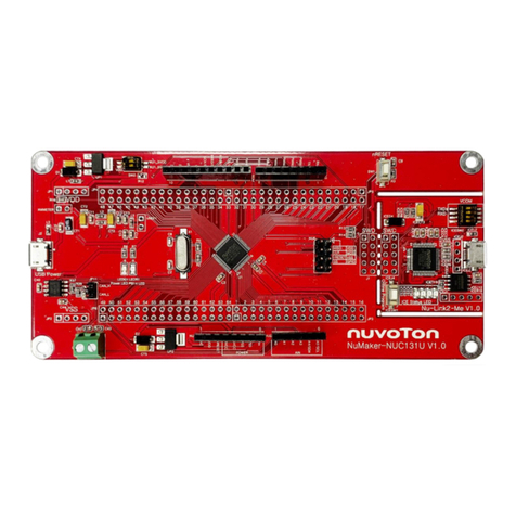
Nuvoton NuMicro ARM Cortex M User manual

ISP Programming Tool
Sep. 05, 2018 Page 1of 11 Rev 2.05
ISP PROGRAMMING TOOL USER MANUAL
ARM®Cortex®- M
32-bit Microcontroller
NuMicro® ISP Programming Tool
User Manual
The information described in this document is the exclusive intellectual property of
Nuvoton Technology Corporation and shall not be reproduced without permission from Nuvoton.
Nuvoton is providing this document only for reference purposes of NuMicro microcontroller based system
design. Nuvoton assumes no responsibility for errors or omissions.
All data and specifications are subject to change without notice.
For additional information or questions, please contact: Nuvoton Technology Corporation.
www.nuvoton.com

ISP Programming Tool
Sep. 05, 2018 Page 2of 11 Rev 2.05
ISP PROGRAMMING TOOL USER MANUAL
Table of Contents
1Overview.............................................................................................3
2Nuvoton Standard ISP Code .....................................................................4
2.1 Pin Definition ........................................................................................... 5
3Using the ISP Programming Tool in Windows.................................................6
3.1 Connecting Interface Selection...................................................................... 6
3.2 Connecting to the target chip ........................................................................ 7
3.3 Load File ................................................................................................ 7
3.4 Setting the User Configuration Bits ................................................................. 9
3.5 Programming Options................................................................................10

ISP Programming Tool
Sep. 05, 2018 Page 3of 11 Rev 2.05
ISP PROGRAMMING TOOL USER MANUAL
1 OVERVIEW
The “ISP” (In-System Programming) tool allows the embedded Flash memory to be
reprogrammed under software control through the firmware using on-chip connectivity interface,
such as UART and USB, without removing any microcontroller from the system.
For NuMicro®Family microcontroller (MCU) products, the on-chip Flash memory is partitioned into
three blocks: APROM, Data Flash and LDROM. The APROM saves the user application program
developed for a specific application; the Data Flash provides storage for nonvolatile application
data; and the LDROM saves the ISP code for MCU to update its APROM/Data Flash/CONFIG.
User can update the MCU’s APROM, Data Flash, and User Configuration bits with Nuvoton
standard ISP code programmed in LDROM easily by using the ISP function.

ISP Programming Tool
Sep. 05, 2018 Page 4of 11 Rev 2.05
ISP PROGRAMMING TOOL USER MANUAL
2 NUVOTON STANDARD ISP CODE
The Nuvoton standard ISP code for NuMicro®MCUs is included in the folder [(2) Nuvoton
Standard ISP Code]. User can program the ISP code into LDROM by using a universal
programmer or Nuvoton’s NuMicro®ICP Programming Tool, and the User Configuration bit ‘CBS’
configured as Boot from LDROM.
The ISPTool samples repository is available on GitHub and GITEE.
Please check the following link to get the latest update.
https://github.com/OpenNuvoton/ISPTool or https://gitee.com/OpenNuvoton/ISPTool

ISP Programming Tool
Sep. 05, 2018 Page 5of 11 Rev 2.05
ISP PROGRAMMING TOOL USER MANUAL
2.1 Pin Definition
Pins used as following for each interface
MCU Parts
UART Port RX/TX
USB
M051/M058S/M0519
UART0 P3.0/P3.1
-
M0518
UART0 PB.0/PB.1
-
M0564
UART0 PD.0/PD.1
-
NUC029xAN
UART0 P3.0/P3.1
-
NUC029FAE
UART0 P1.2/P1.3
-
NUC029xDE
UART0 PB.0/PB.1
-
NUC029xEE
UART0 PB.0/PB.1
PA.10 low
Mini51DE/Mini55/Mini58
UART0 P1.2/P1.3
-
Mini57
USCI UART0 PD.6/PD.5
-
Nano100A/Nano100B
UART0 PA.14/PA.15
PB.15 low
Nano102_112
UART0 PB.1/PB.0
-
Nano103
UART0 PB.0/PB.1
-
NUC100
UART1 PB.4/PB.5
PB.15 low
NUC121
UART0 PB.0/PB.1
PB.0 low
NUC122
UART1 PB.4/PB.5
PA.10 low
NUC123
UART1 PB.4/PB.5
PB.14 low
NUC126
UART0 PD.0/PD.1
PD.0 low
NUC131
UART0 PB.0/PB.1
-
NUC200_220/ NUC230_240
NUC2201
UART0 PB.0/PB.1
PA.10 low
M2351
UART0 PB.12/PB.13
PB.12 low
NUC472_442
UART0 PA.13/PA.14
PB.15 low
NUC505
UART0 PB.1/PB.0
PB.14 low
M451
UART0 PD.0/PD.1
PB.6 low
M4521
UART0 PD.0/PD.1
PD.0 low
M480
UART0 PB.12/PB.13
PB.12 low
NM1120
USCI UART0 PD.6/PD.5
-
NM1200_1100
UART0 P1.2/P1.3
-
NM1530
UART0 P3.0/P3.1
-
I91000 (ISD9000)
UART0 PA.11/PA.10
-
I91200
UART0 PA.5/PA.4
-
I94100
UART0 PB.9/PB.8
PD.2 low
ISD9100
UART0 PA.9/PA.8
-
Table 2-1 Pin Definition

ISP Programming Tool
Sep. 05, 2018 Page 6of 11 Rev 2.05
ISP PROGRAMMING TOOL USER MANUAL
3 USING THE ISP PROGRAMMING TOOL IN WINDOWS
The ISP Programming Tool is contained in the folder [(1) Application Program].
3.1 Connecting Interface Selection
User needs to select the ISP connection interface before using the ISP function and makes sure
the IO pins used for communication are connected correctly. For USB interface, an extra entry pin
must be tied to ground pin to enter ISP mode. Please refer to Table 2-1 Pin Definition for all ISP
samples.
Figure 3-1 Connection via USB Interface
Figure 3-2 Connection via UART Interface using specific COM port

ISP Programming Tool
Sep. 05, 2018 Page 7of 11 Rev 2.05
ISP PROGRAMMING TOOL USER MANUAL
Figure 3-3 Main Dialog
3.2 Connecting to the target chip
After clicking the “Connect”button, the ISP tool will keep trying to connect to a target board every
30 ms until the target board is successfully connected or the “Stop”button is clicked. If there is no
response from the target board during connection, please reset the MCU to execute the ISP code.
3.3 Load File
Click the “APROM”or “Data Flash”button to select the image from the pop-up window. Or using
drag & drop function from Windows Explorer to select the image file.

ISP Programming Tool
Sep. 05, 2018 Page 8of 11 Rev 2.05
ISP PROGRAMMING TOOL USER MANUAL
Figure 3-4 Click Button to Load Image file
Figure 3-5 Drag image file from explorer window

ISP Programming Tool
Sep. 05, 2018 Page 9of 11 Rev 2.05
ISP PROGRAMMING TOOL USER MANUAL
3.4 Setting the User Configuration Bits
After clicking the “Setting”button, a “User Configuration”dialog will open to display all User
Configuration settings. The corresponding “User Configuration”dialog will be displayed
according to the MCU currently connected. Figure 3-6 shows the “User Configuration”setting of
the NUC123AN series MCU.
The ISP tool does not allow user to modify target board boot selection, either. The “Boot Select”
shown in the User Configuration form is for informative purpose only. This setting can be updated
with Nuvoton’s NuMicro®ICP Programming Tool.
Figure 3-6 User Configuration Dialog

ISP Programming Tool
Sep. 05, 2018 Page 10 of 11 Rev 2.05
ISP PROGRAMMING TOOL USER MANUAL
3.5 Programming Options
The following table lists the ISP actions for different programming options.
Programming Options
ISP Actions
APROM
APROM will be updated.
Data Flash
Data Flash will be updated.
Config
User Configuration will be updated while target chip is
not in write protected mode.
1. User Configuration is in write protected mode when
security lock is enabled.
2. Program APROM or Erase All option can remove
write protection of User Configuration.
Erase All
APROM and Data Flash will be erased.
The Security Lock in User Configuration will be
disabled.
Jump to APROM
The system reset is issued and the chip is running user
application on APROM.
Table 3-7 ISP Programming Options

ISP Programming Tool
Sep. 05, 2018 Page 11 of 11 Rev 2.05
ISP PROGRAMMING TOOL USER MANUAL
Important Notice
Nuvoton Products are neither intended nor warranted for usage in systems or equipment, any
malfunction or failure of which may cause loss of human life, bodily injury or severe property
damage. Such applications are deemed, “Insecure Usage”.
Insecure usage includes, but is not limited to: equipment for surgical implementation, atomic
energy control instruments, airplane or spaceship instruments, the control or operation of
dynamic, brake or safety systems designed for vehicular use, traffic signal instruments, all
types of safety devices, and other applications intended to support or sustain life.
All Insecure Usage shall be made at customer’s risk, and in the event that third parties lay
claims to Nuvoton as a result of customer’s Insecure Usage, customer shall indemnify the
damages and liabilities thus incurred by Nuvoton.
Table of contents
Other Nuvoton Controllers manuals
Popular Controllers manuals by other brands

Honeywell
Honeywell 023350.17 Mounting and Connection Instructions

Autani
Autani CORE/Manager user manual

PRECISION DIGITAL
PRECISION DIGITAL PD6210-6R2 instruction manual

AUMA
AUMA SA Series manual

Dynamatic
Dynamatic 4000 instruction manual

RKC INSTRUMENT
RKC INSTRUMENT CB100 Series Communication instruction manual