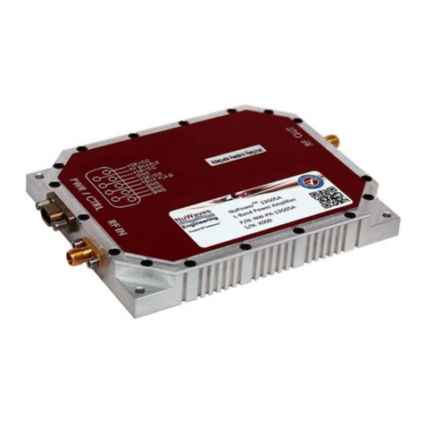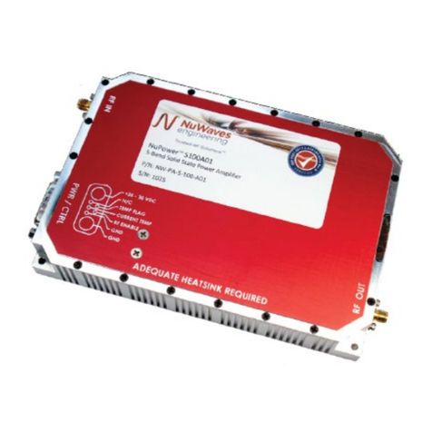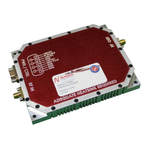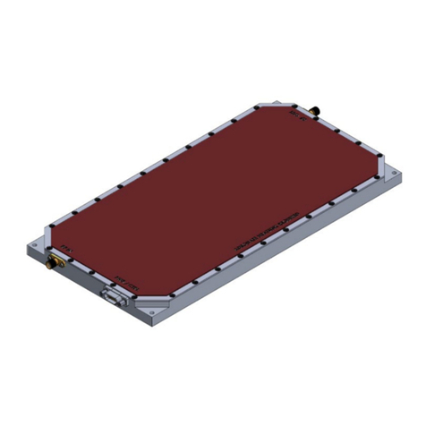
NuPower
TM
C20R01UserManual
Rev1.0
6
3 SETUP AND OPERATION
This section provides specific details for proper operation of the NuPower C20R01 module. Following
theseguidelineswillpreventdamagetothepoweramplifierorexternalequipment.
3.1 POWER SUPPLY REQUIREMENTS
TooperatetheNuPowerC20R01,ensurethatthe powersupplyhasadequateoverheadtosourcethe
currentdemandoftheRFpoweramplifier.Thepowersupplysourcemustprovideatypicalvoltageof
+28VDCwithgreaterthan6ampscapability.
3.2 CONNECTING A PROPER LOAD TO THE ANTENNA TERMINAL
TopreventdamagetothePA,theantennaterminalmustbeterminatedintoa50Ωload.Examplesofa
properloadinclude:
Directlyconnectingtoanantennaspecifiedforthefrequencyrange(4400MHzto4900MHz).
ConnectingtoaninappropriateantennamayresultindamagetothePAmodule.
Connectingtoaproperantennathrougha50Ωtransmissionlineorcoaxialcable.Avoidusing
damagedcablesorcorrodedconnectorswhileattachingtheunittoanantenna.
Terminating the antenna terminal into a 50 Ω power attenuator with minimum 20 dB
attenuation.
ConnectingtoaloadcapableofdissipatingtheRFpowerfromthePAmodule.Loadscapableof
handling50Watts(min)arerecommended.
3.3 POWERING‐UP THE NUPOWER C20R01
TheNuPowerC20R01mustbeterminatedtoaproperloadbeforepowerisapplied.RefertoSection3.2
forthespecificationsoftheproperload.AfterthePAisproperlyterminated,theinterfacecablecanbe
connectedtotheunitandpowercanbeapplied.ThePAisnowreadyforoperation.
3.4 TRANSMIT TURN‐ON TIME
Caution:DonotapplytransmitdatauntilthePAmoduleisatfullpower.Thiswillprevent
lossofdataatthebeginningofamessage.
The NuPower C20R01 is at full power approximately 1 µS after the RF Enable line goes low (ground).
Therefore,transmitdatacanbeappliedtotheinputafter1µSwithoutlossofdata.
3.5 RF OUTPUT POWER VS. SUPPLY VOLTAGE
TheNuPowerC20R01wasdesignedfor+28VDCoperation.

