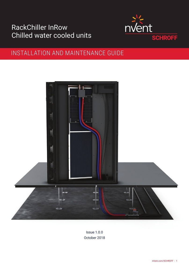
nvent POWERLEAN PL782442IR3 User manual

© 2018 nVent 89074457
Rev. B P/N 89074455
POWERLEAN™
IN-ROW COOLING UNIT
PL782442IR3, PL783642IR5
INSTRUCTION MANUAL

© 2018 nVent 89074457
- 2 -
WARRANTY AND RETURN POLICY
Visit hoffman.nVent.com/warranty-information
TABLE OF CONTENTS
Warranty and Return Policy............................................................................................................................................................. 2
HOW TO UNPACK THE ENCLOSURE.............................................................................................................................................. 3
LEVELING THE EQUIPMENT........................................................................................................................................................... 3
SPECIFICATIONS ............................................................................................................................................................................. 4
Design Data..................................................................................................................................................................................................... 4
SERVICE PARTS .............................................................................................................................................................................................. 5
Dimensional Drawings ................................................................................................................................................................................... 6
78x24x42 In-row Cooling Unit, 31kW.................................................................................................................................................... 6
78x36x42 In-row Cooling Unit, 52kW.................................................................................................................................................... 7
Wire Diagram................................................................................................................................................................................................... 8
ELECTRICAL CONNECTIONS.......................................................................................................................................................... 9
MOTOR CONTROL CARD CONNECTION ....................................................................................................................................... 9
MINIMUM AND MAXIMUM OPERATING CONDITIONS................................................................................................................ 9
CONDENSATE PUMP WIRING ........................................................................................................................................................ 9
WATER QUALITY.............................................................................................................................................................................. 9

© 2018 nVent
89074457 - 3 -
HOW TO UNPACK THE ENCLOSURE
This equipment poses a risk of tipping over. Read and follow the included Large Enclosure
Handling Manual before handling this product; P/N 35320001. If you have any questions
howto safely handle this product or you would like additional copies of this manual,
call1-800-355-3560.
LEVELING THE EQUIPMENT
The leveling feet at the corners of the equipment provide a stable base, but they cannot compensate for a badly
sloped surface.
Cabinet
Door and
Frame
Coil
Fan
Air Filters
Electrical
Panel
Direct
Dirve
Motors
Leveling
Legs
Casters
Open the front and rear doors. For each leveling foot, place an appropriately sized wrench on the hex head that
extends directly above the leveling foot. Turn the wrench clockwise to extend the leveling foot until it makes rm
contact with the oor. In the event of an uneven surface, each foot may need individual adjustment to level the
equipment. Cooling unit should be leveled to within .125 inch (3 mm) in both directions.
Potentially dangerous and lethal voltages exist within this unit.
Always disconnect electrical power supplies before leveling or
servicing.
CAUTION

© 2018 nVent 89074457
- 4 -
SPECIFICATIONS
DESIGN DATA
Catalog Number
PL782442IR3 PL783642IR5
Cooling Performance
Cooling Cap at 85°F air temp 31 kW 52 kW
Cooling Cap at 100°F air temp 43 kW 71 kW
CFM 4,600 7,600
Entering Coolant 44°F 44°F
Entering Air Relative Humidity 45% 45%
Variable speed Yes Yes
Filter size 4 4
Physical characteristics
Height (in./mm)* 78 / 1981 78 / 1981
Width (in./mm)* 24 / 610 36 / 914
Depth (in./mm)* 42 / 1067 42 / 1067
Shipping Weight 550 lb 825 lb
Color Black Black
Fan Arrangement 2 3
Type of fan Plenum Plenum
Sound Level
At 1.5 meters 60 dBA 63 dBA
Hydraulic
“Valve, Optional” 3-way 3-way
Pressure drop 14.3 ft H20 15.3 ft H20
Fluid Flow 13.9 GPM 23.1 GPM
“Pump, Optional” dual oat dual oat
Power
Nominal Input Voltage 460 3-ph
Other Input congurations 460v/1 ph, 208v/1ph, 208v/3ph, 120v/1ph
Power consumed 0.58 kW 0.97 kW
kW input to 1 kW cooled (@ 85°F air
temp) 0.019 kW 0.019 kW
kW input to 1 kW cooled (@ 100°F air
temp) 0.013 kW 0.014 kW
Input Connections Hard wire Hard wire
Input Frequency 60Hz 60Hz
Control (Optional)
BMS compatible Optional controller available
Communication protocols Optional (SNMP, BACnet, Modbus)
Control panel PLC
* Does not included water lines

© 2018 nVent
89074457 - 5 -
SERVICE PARTS
Part Description Model Item
1/2 hp EC motor PL05HPECMTRSP 23558
1/30 hp dual oat condensate pump PL003HPPMPSP 23561
24v ECM speed control card PL24VMCCSP 23562
Dual transformer PL24VCTFMSP 23564
7 amp fuse PL7AMPFSSP 23565
2 amp fuse PL2AMPFSSP 23566
Controller PLCNTRLR 23563

© 2018 nVent 89074457
- 6 -
DIMENSIONAL DRAWINGS
78X24X42 IN-ROW COOLING UNIT, 31KW
' %)
#%(
)( ""
#+%"
$ ""
'#
5:;>>76
I3F7D
EGBB>K
5:;>>76
I3F7D
D7FGD@
3;D
8>AI
&$ $&
#")%
% '"
*+
% '"
*+
+ (+
$&(
$& #$
(#%
CHILLED
WATER
SUPPLY
CHILLED
WATER
RETURN
AIR
FLOW

© 2018 nVent
89074457 - 7 -
78X36X42 IN-ROW COOLING UNIT, 52KW
CHILLED
WATER
RETURN
AIR
FLOW
36.12
917
76.00
1930
2.00
51
5.37
136
42.00
1067
CHILLED
WATER
SUPPLY
5.62
143
13.19
335
16.19
411
CHILLED
WATER
SUPPLY
CHILLED
WATER
RETURN
AIR
FLOW

© 2018 nVent 89074457
- 8 -
WIRE DIAGRAM
/ / /
%ODFN
%ODFN
*UHHQ
*1'
/
1
*
0
/
1
*
0
*UHHQ
*1'
%ODFN
%ODFN
&2176,*1$/
6LJQDO&20
5302XW
&20
9DFGF
9DFGF
1HXWUDO
&20
&RQWURO6LJQDO
530)HHGEDFN
$8;3RZHU
3RZHU6RXUFH
(92&RQWUROOHU&DUG
%ODFN
%ODFN
)URP%XLOGLQJ
&RQWURO
9GF
9
%ODFN
1
0
/
1
*
0
*UHHQ
*1'
%ODFN
%ODFN
%ODFN
7HUPLQDO%ORFN
9
)
)
BBB$
BBB$
)
)
)
)
BBB$
BBB$
BBB$
BBB$
*1'
)
)
BBB$
BBB$
)
)
BBB$
BBB$
5HG96SG
*UHHQ&20
%ODFN530
:KLWH*R6LJ
1&
1&
1&
1&
1&
0
&RQWURO
0
&RQWURO
(6WRS )LUH :DWHU +LJK:DWHU
3XPS:DUQLQJ
%ODFN
&
<HO9
2UJ9
%ON9
:KW&20
%ODFNY
&RQGHQVDWH3XPS2SWLRQDO
&RQGHQVDWH3XPS
9$&$PSV
,QWHUQDOO\3URWHFWHG
&RQWUROOHG
,QFK0RGHO2QO\
&
%ODFN
0
&RQWURO
LQ0RGHORQO\ &
%ODFNY
&20
<HOORZ%URZQ
2UDQJH
<HOORZ
%URZQ
2UDQJH
:KLWH
%ODFN9
:KLWH
:KLWH
%OXH
5HG
%ODFN
2UDQJH:KLWH
5HG
%OXH
%OXH
) &&05
) &&05
) &&05
) &&05
) &&05
) &&05
) ./.5
) ./.5
)
)
)XVH &KDUW
CONDENSATE PUMP 115
VAC 1.5 AMPS INTERNALLY
PROTECTED AND
CONTROLLED
ORANGE
ORANGE
ORANGE
E-STOP
WHITE
WHITE
FIRE WATER
BLUE 2
BLUE 2
HIGH WATER
PUMP WARNING
CONTROL SIGNAL
SIGNAL
NEUTRAL
WHITE
BLACK
GREEN
RED
OUT
CONTROL SIGNAL
POWER SOURCE
CONTROLLER CARD
FEEDBACK
POWER
FROM BUILDING
CONTROL
BLACK
BLACK
BLACK
BLACK
BLACK
BLACK
BLACK
BLACK
CONTROL
CONTROL
CONTROL
IN MODEL ONLY
WHITE
RED
RED
BLACK
GREEN
GREEN
GREEN
BLACK
BLACK
BLACK
BLACK
BLACK
BLACK
BLACK
BLACK
ORANGE / WHITE
YELLOW / BROWN
FUSE CHART
36 INCH MODEL ONLY
CONDENSATE PUMP (OPTIONAL)
TERMINAL BLOCK
BROWN
YELLOW
YELLOW
BLUE 1
WHITE

© 2018 nVent
89074457 - 9 -
ELECTRICAL CONNECTIONS
The following electrical connections are required in the eld:
• Power
• Controls (motor control card)
• Optional condensate pump is powered by the unit. Separate connection is not required.
All electrical connections must be in accordance with local and national codes and regulations.
Refer to electrical wiring diagram for power, controls and condensate pump connection points.
See the equipment nameplate for voltage and current requirements.
All low voltage connections must be made with properly insulated wires.
Line voltage and low voltage or control wires need to be in separate conduits.
MOTOR CONTROL CARD CONNECTION
Motor speed is controlled by an external control signal. A terminal is provided in the electrical control panel for
this connection.
Refer to electrical wiring diagram on the inside of the electrical panel for power, controls and condensate pump
connection points.
MINIMUM AND MAXIMUM OPERATING CONDITIONS
Unit is designed for indoor operation. Facilities with hot aisle temperatures outside the range of 80 F (27 C) -
115 F (46 C) and entering chilled water temperatures at 44 F (7 C) - 64 F (18 C) should consult nVent Technical
Products. Maximum water draining pressure is 125 PSI.
CONDENSATE PUMP WIRING
Refer to electrical wiring diagram on the inside of the electrical panel for power, controls and condensate pump
connection points.
WATER QUALITY
Chilled water loop must be kept clean of dirt, sediment and corrosive elements. System strainers or lter are
recommended. Chilled water system must be vented to insure air is not trapped in the piping or coils.

© 2018 nVent 89074457
- 10 -
NOTES

© 2018 nVent
89074457 - 11 -
NOTES

© 2018 nVent 89074457
Rev. B P/N 89074455
P8GPV
*QHHOCP9
C[
#
PQMC/075#
P8
GPVEQO
This manual suits for next models
1
Table of contents
Other nvent Computer Hardware manuals
Popular Computer Hardware manuals by other brands

Renesas
Renesas RA4 Series user manual

Advantech
Advantech ARK-1551 user manual

Mitsubishi Electric
Mitsubishi Electric VC-X3000 user manual

Extron electronics
Extron electronics Dual Window Multi-Graphic Processor MGP 462D Specification sheet

Aurora
Aurora EGO AE120 user manual

Ametek
Ametek Reichert 13778 quick start guide