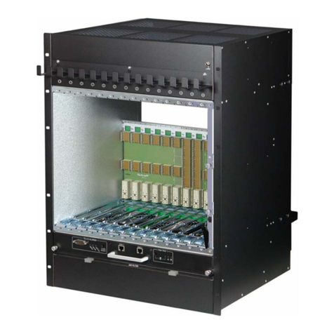
nvent SCHROFF 11990-19 Series User manual

14U 14-slot ATCA Shelf
User Manual
Product Number:
11990-190/192
Doc-No: 63972-374_R1.0 October 2018

Impressum:
Schroff GmbH
Langenalber Str. 96 - 100
75334 Straubenhardt, Germany
The details in this manual have been carefully compiled and
checked - supported by certified Quality Management System
to EN ISO 9001/2000
The company cannot accept any liability for errors or misprints.
The company reserves the right to amendments of technical
specifications due to further development and improvement of
products.
Copyright2018
All rights and technical modifications reserved.
R1.0 October 2018 Initial Release

11990-190/192
1 R1.0, October 2018
Table of Contents
1 Safety .................................................................................................................................... 1
1.1 Safety Symbols used in this document............................................................................ 1
1.2 General Safety Precautions ................................................................................................ 1
1.3 References and Architecture Specifications ................................................................... 2
1.4 Product definition ................................................................................................................. 2
1.5 Terms and Acronyms .......................................................................................................... 3
2 Hardware Platform............................................................................................................. 4
2.1 Shelf Front and Rear View................................................................................................... 5
2.2 ESD Wrist Strap Terminals.................................................................................................. 8
3 ATCA Backplane ................................................................................................................. 9
3.0.1 Base Interface ....................................................................................................... 9
3.0.2 Dual Star Fabric Interface).................................................................................. 9
3.0.3 Synchronization Clock Interface........................................................................ 9
3.0.4 Update Channel Interface ................................................................................... 9
3.0.5 Power Interface..................................................................................................... 9
3.1 Backplane Overview ........................................................................................................... 10
3.2 Dedicated Shelf Manager Slots........................................................................................ 10
3.2.1 Intelligent Platform Management Interface .................................................. 11
3.3 Chassis Data Modules (CDM) .......................................................................................... 12
3.4 Shelf Manager Cross Connect ......................................................................................... 13
3.5 Logic Ground (GND) and Shelf Ground (Shelf_GND) ................................................... 14
4 Air Filter............................................................................................................................... 15
4.1 Introduction.......................................................................................................................... 15
4.2 Air Filter Replacement/Maintenance .............................................................................. 15
5 Shelf Ground Connection ................................................................................................ 16
5.1 Specification for the Shelf Ground connection cable .................................................. 16
6 Fan Trays............................................................................................................................ 17
6.1 Introduction.......................................................................................................................... 17
6.2 Maintenance/Service ......................................................................................................... 18
6.3 Fan Tray Block Diagram .................................................................................................... 19
6.4 Fan Tray Signals ................................................................................................................. 20
6.5 Fan Tray Temperature Sensor ......................................................................................... 20
6.6 Fan Tray Connectors and Indicators .............................................................................. 20
6.7 Telco Alarms........................................................................................................................ 21
6.7.1 Telco Alarm Interface ........................................................................................ 21
6.7.2 Telco Alarm LEDs ............................................................................................... 21
6.7.3 Alarm Silence Push Button ............................................................................... 21

11990-190/192
2 R1.0, October 2018
6.7.4 Alarm Reset ......................................................................................................... 21
6.7.5 Telco Alarm Connector (DB15-male).............................................................. 22
6.8 RS-232 Serial Console Interfaces.................................................................................... 23
7 Thermals............................................................................................................................. 24
7.1 System Airflow Path 11990-190 ...................................................................................... 24
7.2 System Airflow Path 11990-192 ...................................................................................... 25
7.3 Front slot measurement zones........................................................................................ 26
7.4 Front Board Air Distribution .............................................................................................. 27
7.5 Rear Board Air Distribution ............................................................................................... 29
8 Power Entry Module (PEM)............................................................................................. 31
8.1 Introduction.......................................................................................................................... 31
8.2 PEM Front View................................................................................................................... 33
8.3 Specifications for the Power Cables............................................................................... 34
8.4 Power Branches.................................................................................................................. 36
8.5 Slot Power Calculation....................................................................................................... 36
8.6 PEM Block Diagram............................................................................................................ 37
8.7 PEM Fuses ........................................................................................................................... 38
8.8 PEM I²C-bus addresses..................................................................................................... 39
8.9 PEM I/O Device ................................................................................................................... 39
9 Shelf Management ........................................................................................................... 40
9.1 Schroff Shelf Manager ACB-VI......................................................................................... 41
9.2 Front Panel Components .................................................................................................. 43
9.3 Bused IPMB Interface ........................................................................................................ 44
9.4 Ethernet Interfaces ............................................................................................................. 45
9.5 Shelf Manager RS-232 Console Serial Interface........................................................... 47
9.6 Front Panel RESET push button ...................................................................................... 47
9.7 Hot Swap Interface............................................................................................................. 48
9.7.1 Hot Swap LED ..................................................................................................... 48
9.8 Hardware Address.............................................................................................................. 48
9.9 Redundancy Control........................................................................................................... 49
9.9.1 Hardware Redundancy Interface..................................................................... 49
9.10 Command Line Interface (CLI)......................................................................................... 50
9.10.1 Basic CLI Commands ........................................................................................ 50
9.11 Sensor Table........................................................................................................................ 52
9.12 Shelf Manager Front Panel and Backplane connectors.............................................. 58
10 Technical Data................................................................................................................... 62
10.1 Shelf Mechanical Dimensions.......................................................................................... 63

11990-190/192
Safety 1 R1.0, October 2018
1 Safety
The intended audience of this User’s Manual is system integrators and
hardware/software engineers.
1.1 Safety Symbols used in this document
1.2 General Safety Precautions
• Service personnel must know the necessary electrical safety, wiring and connec-
tion practices for installing this equipment.
• Install this equipment only in compliance with local and national electrical codes.
•For additional information about this equipment, see the PICMG 3.0
Specification (www.picmg.com).
Hazardous voltage!
This is the electrical hazard symbol. It indicates that there are dangerous
voltages inside the Shelf.
Caution!
This is the user caution symbol. It indicates a condition where damage of the
equipment or injury of the service personnel could occur. To reduce the risk of
damage or injury, follow all steps or procedures as instructed.
Danger of electrostatic discharge!
TheShelfcontainsstaticsensitivedevices.Toprevent staticdamage youmust
wear an ESD wrist strap.
Warning!
Voltages over 60 VDC can be present in this equipment. As defined in the
PICMG 3.0 Specification, this equipment is intended to be accessed, to be
installed and maintained by qualified and trained service personnel only.

11990-190/192
Safety 2 R1.0, October 2018
1.3 References and Architecture Specifications
• Pigeon Point Systems IPM Sentry Shelf-External Interface Reference
(www.pigeonpoint.com)
•PICMG
®3.0 R3.0 AdvancedTCA® Base Specification
(www.picmg.com)
• AdvancedTCA base extensions specification PICMG-3.7 Revision-1.0 section 5
for the cooling aspects.
• Intel specification: IPMI v2.0
• EMC compliance: CISPR22 and CISPR24 Class A and IEC/EN 61000-6-3;
• Safety standard: IEC/EN 60950-1
• CERN safety regulations IS-23 and IS-41.
• Ethernet standard: IEEE standard 802.3
• SNMP v3: RFCs 3413 to 3415.
• ROHS compliance: WEEE Directive 2012/19/EU
• CE compliance and related regulations.
• Schroff Shelf Manager User‘s Manual, Order-no. 63972-243
1.4 Product definition
The Schroff 11990-19x is a 14 U / 14 Slot ATCA 40G Shelf with enhanced
per-slot power and cooling capability along with 40G backplane connectivity and
bused IPMB.
• Product Number 11990-190: Airflow from bottom to top
• Product Number 11990-192: Airflow front to rear
The Schroff 11990-19x is designed to work with two redundant
Schroff ShMM-ACB-VI Shelf Managers. At least one Shelf Manager is needed for a
working System.

11990-190/192
Safety 3 R1.0, October 2018
1.5 Terms and Acronyms
Table 1: Terms and Acronyms
Term Definition
ATCA Advanced Telecom Computing Architecture
Backplane Passive circuit board providing the connectors for the front boards. Power distribution,
management and auxiliary signal connections are supported
CDM Chassis Data Module
Chassis Enclosure containing subrack, Backplane, boards, cooling devices, PEMs, same as Shelf
CMM Chassis Management Module, same as Shelf Manager
ECN Engineering Change Notice
ESD Electrostatic Discharge
ETSI European Telecommunications Standards Institute
FRU Field Replaceable Unit
IPMB Intelligent Platform Management Bus
IPMC Intelligent Platform Management Controller
IPMI Intelligent Platform Management Interface
PCB Printed Circuit Board
PEM Power Entry Module
RTC Real Time Clock
RTM Rear Transition Module
Shelf See Chassis
VRTN Voltage Return

11990-190/192
Hardware Platform 4 R1.0, October 2018
2 Hardware Platform
• Mounting brackets for 19“ cabinets
• ESD Wrist Strap Terminals at the front and the rear
• 14 slot ATCA 40G/100G Backplane with Dual Star Fabric Interface, Dual
Star Base Interface and bused IPMB interface, supporting twelve 8 U node
board slots and two 8 U hub slots
• 2 dedicated Shelf Manager slots accepting Schroff ShMM-ACB-VI Shelf
Managers
• Electrical power 450 W/slot
• Enhanced cooling capability:
The shelf cooling capability complies with chapter 5 of PICMG-3.7 R1.0 for
Data Centre environmental conditions.
• Airflow of minimum 65 CFM per slot will be guaranteed in all slots at maxi-
mum fan speed for a supply voltage of 48Vdc.
• The cooling capability will be verified by thermal measurement acc. to
CP-TA procedure.
• Push-Pull Fan Tray arrangement provides optimized cooling for ATCA
blades with fault tolerant capability
• Two pluggable, hot swappable Fan Trays
• Telco Alarm interface, Alarm Status LEDs, Fan Tray Alarm LEDs and serial
interfaces for the Shelf Managers on bottom Fan Tray
• Rear pluggable dual redundant Power Entry Modules (PEM) with enhanced
electrical power capability with 210 A per PEM: Each PEM has 6 internal
power branches and providing connection of one power feed.
The torque of all FRU (Fan Tray, Air Filter, PEM, PEM cover) fixing screws is
0.7 Nm (6.2 in-lbs)

11990-190/192
Hardware Platform 5 R1.0, October 2018
2.1 Shelf Front and Rear View
Figure 1: Shelf 11990-190 Front View
1Front Cable Tray 6Slot for Shelf Manger 1
2ATCA 14-Slot Backplane 7Shelf Manager 2
3Front Card Cage 8Serial Interfaces for the Shelf Managers
4Fan Tray 1 9Air Filter Tray
5ESD Wrist Strap Terminal

11990-190/192
Hardware Platform 6 R1.0, October 2018
Figure 2: 11990-190 Shelf Rear View
10 Fan Tray 2 13 Rear Cable Tray
11 Rear Card Cage 14 Power Entry Module A (PEM A)
12 Power Entry Module B (PEM B) 15 PEM Cover

11990-190/192
Hardware Platform 7 R1.0, October 2018
Figure 3: Shelf 11990-192 Front View
1Front Cable Tray 6Slot for Shelf Manger 1
2ATCA 14-Slot Backplane 7Shelf Manager 2
3Front Card Cage 8Serial Interfaces for the Shelf Managers
4Fan Tray 1 9Air Filter Tray
5ESD Wrist Strap Terminal

11990-190/192
Hardware Platform 8 R1.0, October 2018
Figure 4: 11990-192 Shelf Rear View
2.2 ESD Wrist Strap Terminals
Two ESD Wrist Strap Terminals (4 mm banana jacks) are located at the upper
front and lower rear side of the Shelf.
10 Fan Tray 2 13 Rear Cable Tray
11 Rear Card Cage 14 Power Entry Module A (PEM A)
12 Power Entry Module B (PEM B) 15 PEM Cover
Danger of electrostatic discharge!
Static electricity can harm delicate components inside the Shelf. You must wear
an ESD wrist strap before exchanging any part or electric component!

11990-190/192
ATCA Backplane 9 R1.0, October 2018
3 ATCA Backplane
The 14-slot ATCA Backplane provides:
• 40 Gb/s connectivity (4 lanes with 10 Gb/s)
• 12 ATCA Node slots
• Two ATCA Hub slots
• Two dedicated Shelf Manager slots
• Two Power Entry Module (PEM) slots
• Two slots for the Chassis Data Modules (CDM)
3.0.1 Base Interface
Logical slots 1 and 2 are the hub slots for the Dual Star Base Interface.
Base Interface Channel 1 (ShMC) of logical slot 1 and 2 is cross connected to
both dedicated Shelf Manager slots on the ATCA Backplane.
3.0.2 Dual Star Fabric Interface)
The Fabric Interface is routed in aDual Star configuration, supporting fourports
per channel. In the Dual Star backplane, Logical Slots 1 & 2 are dedicated Hub
Slots, Channels 1 & 2 are connected to Channel 1 & 2 of each Node Slot.
3.0.3 Synchronization Clock Interface
6 differential pairs of synchronization clocks are bused between all 14 ATCA
slots and terminated at both ends with 80.5 Ohms between each differential pair.
3.0.4 Update Channel Interface
The Update Channels are wired between two redundant ATCA Backplane slots
as 10 differential pairs with 100 Ohms impedance. The Update Channel is
intended to pass information between two redundant ATCA Boards.
The Update Channel assignment is printed on the frontside of the Shelf.
3.0.5 Power Interface
PowerdistributionwithintheATCA Backplaneisdividedinto6 Power Branches.
Thistopologyis usedfor safetyreasonstokeepthemax.currentper branchless
the 35 A. Slots connected by update ports, are on separate power branches as
well as both hub slots, the Shelf Manager slots and the Fan Trays.

11990-190/192
ATCA Backplane 10 R1.0, October 2018
3.1 Backplane Overview
3.2 Dedicated Shelf Manager Slots
The front accessible Shelf Manager slots accept Schroff ShMM-ACB-VI Shelf
Managers and are wired to:
• IPMB-A and IPMB-B (I²C-bus)
• Base Interface Channel 1 (ShMC) of the Base Interface Hub slots, support-
ing Shelf Manager Cross Connect (10/100 Base T Ethernet)
• Fan Tray connectors
• PEM A and PEM B connector
The dedicated Shelf Manager slots also have interconnected signals that allow
the Shelf Managers to run in a redundant configuration.

11990-190/192
ATCA Backplane 11 R1.0, October 2018
3.2.1 Intelligent Platform Management Interface
The Shelf uses an Intelligent Platform Management Bus (IPMB) for
management communications among all ATCA Boards and the Shelf
Managers. The reliability of the IPMB is improved by the addition of a second
IPMB, with the two IPMBs referenced as IPMB-A and IPMB-B.
IPMB-A and IPMB-B are routed to the ATCA slots in a bused configuration.
Figure 5: Bused IPMB
12712822
Fan Tray 1
ATCA Board
ATCA Board
ATCA Board
Shelf Manager 1 Shelf Manager 2
IPMB-A
IPMB-B
IPMC IPMC IPMC IPMC IPMC IPMC
ATCA Board 1...14
Fan Tray 2
ATCA Board

11990-190/192
ATCA Backplane 12 R1.0, October 2018
3.3 Chassis Data Modules (CDM)
The Chassis Data Module (CDM) is a carrier board for the FRU SEEPROM
(24LC256)
Figure 6: Chassis Data Module 1 (CDM 1)
1
Both CDMs are pluggable modules and located on the rear side of the ATCA
Backplane. The modules can be accessed after removing the respective Power
Entry Module (PEM).
Table 2: Chassis Data Module I²C addresses
12712816
1CDM 1 2Connector PEM A
Warning!
Before removing a PEM, make sure that all Power Feeds of the other PEM are
fully functional.
CDM Channel I²C-bus address
CDM 1, SEEPROM Channel 1 0xa4 / 52
CDM 2, SEEPROM Channel 2 0xa4 / 52

11990-190/192
ATCA Backplane 13 R1.0, October 2018
3.4 Shelf Manager Cross Connect
The ATCA Backplane provides cross connect traces between the Base Hubs
and the Shelf Managers according to PICMG Engineering Change Notice
ECN 3.0-2.0-001. This ECN adds an option for dual 10/100 Base-T links from
each Base Hub to both dedicated Shelf Manager slots.
Figure 7: Shelf Manager Cross Connect
Table 3: Connector (P23) pin assignments for Shelf Manager Cross Connect
12709823
Row Designation ab cd ef gh
5Shelf Manager Port
with Shelf Manager
Cross Connects
Tx1+ Tx1- Rx1+ Rx1- Tx2+ Tx2- Rx2+ Rx2-
Shelf Manager Cross Connect 1 Shelf Manager Cross Connect 2

11990-190/192
ATCA Backplane 14 R1.0, October 2018
3.5 Logic Ground (GND) and Shelf Ground (Shelf_GND)
Figure 8: Logic Ground/Shelf Ground Connection
The ATCA Backplane provides a mechanism to connect Logic Ground (GND)
and Shelf Ground (Shelf_GND). You can connect/isolate Logic Ground by
swapping two screws from position (A) to position (B).
• Screws at position (A): Logic Ground and Shelf Ground connected.
• Screws at position (B): Logic Ground and Shelf Ground isolated.
Torque for the Screws: 0.7 Nm +10%
12706816
Logic Ground and Shelf Ground is not connected by default.

11990-190/192
Air Filter 15 R1.0, October 2018
4 Air Filter
Figure 9: Air Filter
4.1 Introduction
The ATCA Shelf provides a front replaceable air filter.
The filter meets the requirements of the Telcordia Technologies Generic
Requirements GR-78-CORE specification.
4.2 Air Filter Replacement/Maintenance
The air filter tray can be removed by pulling the air filter's handle. To re-install,
push the air filter tray into the guide rails at each side of the shelf until the spring
mounted ball lock engage.
Filter maintenance intervals are application specific and depend on the
environmental conditions. We recommend cleaning or replacing the filter
element approximately every 90 days.
12706958
1Filter Element 3Filter Tray
2Handles 4Spring mounted ball lock
When installing the air filter, the filter element must be in top position

11990-190/192
Shelf Ground Connection 16 R1.0, October 2018
5 Shelf Ground Connection
The shelf ground cable can be connected at the left rear bottom side. For two
hole lugs with 1“ spacing, an adapter kit is available, order no: 21990-413
Figure 10: Shelf ground terminal with adapter kit
5.1 Specification for the Shelf Ground connection cable
Minimum recommended wire size:
AWG3/0 conductor.
Recommended two hole lugs with 1“ spacing for AWG 3/0:
Burndy YAZ272TC38
Burndy YAZ272TC3845 (45°)
Burndy YAZ272TC3890 (90°)
Torque for Bolts M6: 5.1 Nm (45 in.-lb.)
Torque for Bolts M8: 12.6 Nm (111 in.-lb.)
Hazardous voltage!
Before powering-up the Shelf, make sure that the Shelf Ground terminal is
connected to Protective Earth (PE) of the building.
Please note, that in a typical telecom environment, the VRTN path of the -48 V
supply is grounded to Protective Earth (PE) of the building.
12712817
1Shelf Ground Terminal 3Additional fixing point (M6)
2ESD Terminal 4Adapter plate
This manual suits for next models
2
Table of contents
Other nvent Indoor Furnishing manuals
Popular Indoor Furnishing manuals by other brands

FURNITUREBOX
FURNITUREBOX MONACO 8 Assembly guide

Manutti
Manutti Torsa instruction manual

Krugg
Krugg ICON ADA Installation & user guide

Kinfine
Kinfine HOMEPOP K6858.24 Assembly instructions

CRAFTLINE Cabinetry
CRAFTLINE Cabinetry W0930 Assembly instructions

Julian Bowen
Julian Bowen LEN001 Assembly instructions

RH Baby&child
RH Baby&child 130 - 14 quick start guide

Mainstays
Mainstays FOREST HILLS MSS129900298046 Assembly and Care Guide

Whalen
Whalen Tustin Parsons ECOM-PARS1 manual

Courtyard Creations
Courtyard Creations TGS39SW-WM Assembly instructions

Kvik
Kvik OU845 manual

Home Decorators Collection
Home Decorators Collection FCA60401AG Use and care guide