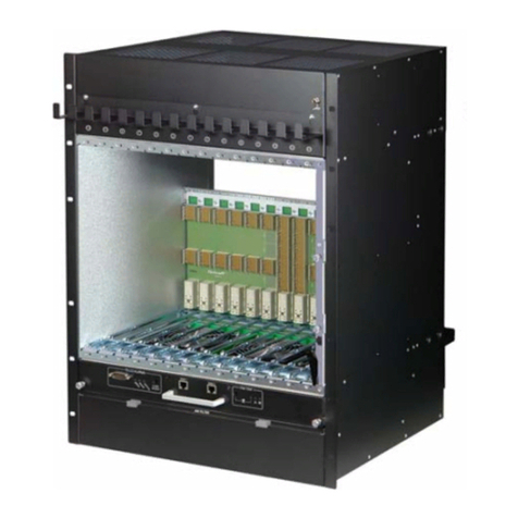
nvent SCHROFF 11990-190 User manual

14U 14-slot ATCA Shelf
Quick Start Guide
Product Number:
11990-190
Doc-No: 63972-373_R1.0 July 2018

Impressum:
Schroff GmbH
Langenalber Str. 96 - 100
75334 Straubenhardt, Germany
The details in this manual have been carefully compiled and
checked - supported by certified Quality Management System
to EN ISO 9001/2000
The company cannot accept any liability for errors or misprints.
The company reserves the right to amendments of technical
specifications due to further development and improvement of
products.
Copyright2018
All rights and technical modifications reserved.
R1.0 July 2018 Initial Release

11990-190
I R1.0, July 2018
Table of Contents
1 Safety .................................................................................................................................... 1
1.1 Safety Symbols used in this document............................................................................ 1
1.2 General Safety Precautions ................................................................................................ 1
1.3 References and Architecture Specifications ................................................................... 1
1.4 Shelf Front and Rear View................................................................................................... 2
1.5 ESD Wrist Strap Terminals.................................................................................................. 3
2 Shelf Installation ................................................................................................................. 4
2.1 Ensuring Overcurrent Protection ....................................................................................... 4
2.2 Ensuring Proper Airflow....................................................................................................... 4
2.3 Creating a Safe Environment.............................................................................................. 4
2.4 Unpacking .............................................................................................................................. 5
2.5 Rack-Mounting ...................................................................................................................... 6
3 Shelf Power Connection.................................................................................................... 7
3.1 Shelf Ground Connection .................................................................................................... 8
3.2 Specification for the Shelf Ground connection cable .................................................... 8
3.3 Power Entry Module ............................................................................................................. 9
3.4 Introduction............................................................................................................................ 9
3.5 PEM Front View................................................................................................................... 10
3.6 Specifications for the Power Cables............................................................................... 11
3.7 Installation the power connection cables ...................................................................... 11
3.8 PEM Fuses ........................................................................................................................... 13
4 Shelf Manager ................................................................................................................... 14
4.1 Ethernet Interfaces ............................................................................................................. 15
4.2 Shelf Manager RS-232 Console Serial Interface........................................................... 15
4.3 Command Line Interface (CLI)......................................................................................... 16
4.3.1 Basic CLI Commands ........................................................................................ 16
5 Technical Data................................................................................................................... 18
5.1 Shelf Mechanical Dimensions.......................................................................................... 19

11990-190
II R1.0, July 2018

11990-190
Safety 1 R1.0, July 2018
1 Safety
The intended audience of this Quick Start Manual is system integrators and
hardware/software engineers.
1.1 Safety Symbols used in this document
1.2 General Safety Precautions
• Service personnel must know the necessary electrical safety, wiring and connec-
tion practices for installing this equipment.
• Install this equipment only in compliance with local and national electrical codes.
1.3 References and Architecture Specifications
• Pigeon Point Systems IPM Sentry Shelf-External Interface Reference
(www.pigeonpoint.com)
•PICMG
®3.0 R3.0 AdvancedTCA® Base Specification
(www.picmg.com)
• Schroff Shelf Manager User‘s Manual, Order-no. 63972-243
The documentation is available for registered users at www.schroff.biz
Hazardous voltage!
This is the electrical hazard symbol. It indicates that there are dangerous
voltages inside the Shelf.
Caution!
This is the user caution symbol. It indicates a condition where damage of the equip-
ment or injury of the service personnel could occur. To reduce the risk of damage or
injury, follow all steps or procedures as instructed.
Danger of electrostatic discharge!
TheShelf containsstatic sensitivedevices.To preventstaticdamageyou must wear
an ESD wrist strap.
Warning!
Voltages over 60 VDC can be present in this equipment. As defined in the
PICMG 3.0 Specification, this equipment is intended to be accessed, to be
installed and maintained by qualified and trained service personnel only.

11990-190
Safety 2 R1.0, July 2018
1.4 Shelf Front and Rear View
Figure 1: Shelf Front View
1Front Cable Tray 6Slot for Shelf Manger 1
2ATCA 14-Slot Backplane 7Shelf Manager 2
3Front Card Cage 8Serial Interfaces for the Shelf Managers
4Fan Tray 1 9Air Filter Tray
5ESD Wrist Strap Terminal

11990-190
Safety 3 R1.0, July 2018
Figure 2: Shelf Rear View
1.5 ESD Wrist Strap Terminals
Two ESD Wrist Strap Terminals (4 mm banana jacks) are located at the upper
front and lower rear side of the Shelf.
10 Fan Tray 2 13 Rear Cable Tray
11 Rear Card Cage 14 Power Entry Module A (PEM A)
12 Power Entry Module B (PEM B) 15 PEM Cover
Danger of electrostatic discharge!
Static electricity can harm delicate components inside the Shelf. You must wear
an ESD wrist strap before exchanging any part or electric component!

11990-190
Shelf Installation 4 R1.0, July 2018
2 Shelf Installation
Choose a site with a dry, clean, well-ventilated and air-conditioned area that
maintains an ambient temperature of 5°C to 45°C (41°F to 113°F).
2.1 Ensuring Overcurrent Protection
The system relies on the protective devices in the building installation for
protection against short-circuit, overcurrent, and earth (grounding) fault. Ensure
that the protective devices in the building installation are properly rated to
protect the system, and that they comply with national and local codes.
2.2 Ensuring Proper Airflow
• Install the system in an open rack whenever possible. If installation in an
enclosed rack is unavoidable, ensure that the rack has adequate ventilation.
• Maintain ambient airflow to ensure normal operation. If the airflow is blocked
or restricted, or if the intake air is too warm, an over temperature condition
can occur.
• Ensure that cables from other equipment do not obstruct the airflow through
the Shelf.
• Use filler panels to cover all empty chassis slots. The filler panel prevents
fan air from escaping out of the front of an open slot.
2.3 Creating a Safe Environment
• Keep tools and chassis components off the floor and away from foot traffic.
• Clear the area of possible hazards, such as moist floors, ungrounded power
extension cables, and missing safety grounds.
• Keep the area around the chassis free from dust and foreign conductive
material.
Caution!
To maintain proper airflow, all open slots must be covered with filler panels.
The filler panel should include an airflow baffle that extends to backplane.

11990-190
Shelf Installation 5 R1.0, July 2018
2.4 Unpacking
Consider the following when unpacking and storing the Shelf:
• Leave the Shelf packed until it is needed for immediate installation.
• After unpacking the Shelf, save and store the packaging material in case the
Shelf must be returned.
• If the packaging is damaged and possible Shelf damage is present, report to
the shipper and analyze the damage.
Caution!
When opening the shipping carton, use caution to avoid damaging the Shelf.
Danger of electrostatic discharge!
The Shelf contains static sensitive devices. While unpacking and handling the
Shelf you must wear an ESD wrist strap to prevent static damage.
Caution!
Do NOT use the Fan Tray and PEM handles or cable trays as lifting points.

11990-190
Shelf Installation 6 R1.0, July 2018
2.5 Rack-Mounting
This ATCA 14-slot Shelf can be installed in 19“ equipment racks. The rack must
be accessible from the front and rear for equipment installation.
Mounting brackets and cable trays come with the system. Allow sufficient
clearance around the rack for system maintenance.
Warning!
Do NOT move the Shelf by yourself. Due to the height and weight of the Shelf,
at least two persons are needed to accomplish this task. We recommend to
use a mechanical lift or remove all hot-swappable equipment for weight
reduction.
Warning!
Do NOT stack the Shelf on top of any other equipment. If the Shelf falls, it can
cause severe bodily injury and damage the equipment.
Caution!
Do NOT remove the Transportation Locks before the Shelf is completely fixed
in the rack.
Caution!
Do NOT use the Fan Tray and PEM handles or cable trays as lifting points.
Danger of electrostatic discharge!
The Shelf contains static sensitive devices. While handling the Shelf you must
wear an ESD wrist strap to prevent static damage.

11990-190
Shelf Power Connection 7 R1.0, July 2018
3 Shelf Power Connection
Hazardous voltage!
Before working ensure that the power is removed from the power connection
cables. When the system is powered on, do NOT touch the power terminals!
Warning!
Avoid electric overload. To avoid electrical hazard, do not make connections
to terminals outside the specified voltage range for that Shelf.
Warning!
Ensurethar the Shelf is grounded.Ensure that the ShelfGroundTerminals are
connected to Protective Earth (PE) of the building.
Warning!
Although there are fuses in thepower entry circuit of the Shelf, the power lines
have to be protected on rack level with breakers.
Warning!
Remove jewelry (rings, watches...) before working on equipment that is
connected to power lines!
Danger of electrostatic discharge!
Static electricity can harm delicate components inside the Shelf. You have to
wear ESD wrist straps before exchanging any part or electric component!
The Shelf can be powered using regular telecommunication power sup-
plies of -48/-60 VDC with a VDC return.
The specified voltage range is from -40.5 VDC to -72 VDC.
The Shelf supports redundant power supplies but the two supplies
should be independently powered.

11990-190
Shelf Power Connection 8 R1.0, July 2018
3.1 Shelf Ground Connection
The shelf ground cable can be connected at the left rear bottom side. For two
hole lugs with 1“ spacing, an adapter kit is available, order no: 21990-413
Figure 3: Shelf ground terminal with adapter kit
3.2 Specification for the Shelf Ground connection cable
Minimum recommended wire size:
AWG3/0 conductor.
Recommended two hole lugs with 1“ spacing for AWG 3/0:
Burndy YAZ272TC38
Burndy YAZ272TC3845 (45°)
Burndy YAZ272TC3890 (90°)
Torque for Bolts M6: 5.1 Nm (45 in.-lb.)
Torque for Bolts M8: 12.6 Nm (111 in.-lb.)
Hazardous voltage!
Before powering-up the Shelf, make sure that the Shelf Ground terminal is
connected to Protective Earth (PE) of the building.
Please note, that in a typical telecom environment, the VRTN path of the -48 V
supply is grounded to Protective Earth (PE) of the building.
12712817
1Shelf Ground Terminal 3Additional fixing point (M6)
2ESD Terminal 4Adapter plate

11990-190
Shelf Power Connection 9 R1.0, July 2018
3.3 Power Entry Module
3.4 Introduction
Two pluggable redundant Power Entry Modules (PEMs) are located at the rear
bottom side of the Shelf
Each PEM provides power terminals for a 210 A power feed. Each power feed
consists of up to four –48 VDC cables and the corresponding return cables.
Each input feed is divided internally at the PEM in 6 output branches toward the
backplane. In this way, each PEM has 1 input feed and 6 output branches.
Over current protection is provided by 50 A fuses in each output branch.
The power filtering consists of filtered power terminals and a discrete line-filter
for each power branch.
The input voltage range for the Shelf is from -40.5 VDC to -72 VDC.
Hazardous voltage!
Before working ensure that the power is removed from the power connection
cables. When the system is powered on, do NOT touch the power terminals.
The Shelf can be powered using a regular telecommunication power supply of
-48/-60 VDC with a VDC return. The specified voltage range is from -40 VDC
to -72 VDC.The Shelf supports redundant power supplies but the two supplies
should be independently powered.

11990-190
Shelf Power Connection 10 R1.0, July 2018
3.5 PEM Front View
Figure 4: PEM Front View
1PEM Cover
2Input Terminal

11990-190
Shelf Power Connection 11 R1.0, July 2018
3.6 Specifications for the Power Cables
The PEM provides 4 M8 studs for the -48 V and the RTN feed to connect the power
cables. The following cabeling scenarios are possible.
1. Single cable wiring:
Connect one cable at the -48 V and one at the RTN feed with a two-hole terminal to
either the upper or lower row of M8 studs.
Required cable size: AWG 3/0, suitable for min. 90°C (194°F), maximum length = 3 m.
Recommended cable lug: Panduit LCD3/0-56D-X or equivalent.
2. Split cable wiring:
Connect two cables at the -48 V and two at the RTN feed as shown in figure (4).
Required cable size: AWG 2, suitable for min. 90°C (194°F), maximum length = 3 m.
Recommended cable lug: Panduit LCDN2-38D-Q or Burndy YA2CL2TC516 or
equivalent.
3.7 Installation the power connection cables
1 Ensure that the power supply is turned off.
2 Remove the terminal cover.
3 Connect the power cables to the power terminal
Torque for Bolts 8-32 UNC 1.4 Nm (12.5 in.-lb.)
Note: Verify the correct polarity of the -48 VDC and the RTN cables!
4 Fix the cables with cable ties.
5 Install the terminal cover.
Caution!
The wiring must be in compliance with local and national electrical codes and
regulations.
The two -48 V and the two RTN cables must be fused separately at the
Power Distribution Unit.

11990-190
Shelf Power Connection 12 R1.0, July 2018
Figure 5: PEM Wiring
PEM
RTN
-48/-60 V
Feed B Feed A
RTN
-48/-60 V
RTN
-48/-60 V
RTN
-48/-60 V
Feed B Feed A
RTN
-48/-60 V
Single cable wiring
Split cable wiring
PEM
RTN
-48/-60 V
PEM
RTN
-48/-60 V
PEM
RTN
-48/-60 V

11990-190
Shelf Power Connection 13 R1.0, July 2018
3.8 PEM Fuses
Figure 6: PEM Fuses
12714800
F101 Fuse Branch 1 (50 A/80 V) F401 Fuse Branch 4 (50 A/80 V)
F201 Fuse Branch 2 (50 A/80 V) F501 Fuse Branch 5 (50 A/80 V)
F301 Fuse Branch 3 (50 A/80 V) F601 Fuse Branch 6 (50 A/80 V)

11990-190
Shelf Manager 14 R1.0, July 2018
4 Shelf Manager
Figure 7: Shelf Manager Front Panel Components
12708844
1Fixing screw 6RESET push button
2ETH 0 Ethernet Service Connector
(RJ45) 7Shelf Manager Status LED (red)
- Red = Out of Service (OOS)
3ETH 0 Link/Activity LED (yellow)
- On = Link
-Off=NoLink
- Blinking = Activity
8Shelf Manager Status LED (green)
- Solid Green = in Service, active
Shelf Manager
- Blinking = in Service, Backup Shelf
Manager
4ETH 1 Link/Activity LED (yellow)
- On = Link
-Off=NoLink
- Blinking = Activity
9Hot Swap Switch
- Activated by extraction handle
5Hot Swap LED (blue)
- Solid Blue = ready to remove
- Blinking = Hot Swap is requested
- Off = No Hot Swap possible
10 Extraction handle

11990-190
Shelf Manager 15 R1.0, July 2018
4.1 Ethernet Interfaces
The front panel ETH0 Ethernet connector is intended for service use only or for
debugging purposes in laboratory environment. The computer which is
connected to this interface must be located nearby the shelf manager with an
Ethernet cable that is not longer than 10 m.
The front panel Ethernet connector MUST NOT be connected to a
Telecommunication Network Circuit that leaves the building.
TheETH0 interfaceofthe shelf managercanmanually beswitchedbetween the
front panel RJ45 connector (“Front”-position of the rocker-switches) and the
backplane connector going to the hub board base interface (“Back”-position of
the rocker-switches).
The ATCA specification requires a base channel interface between the shelf
manager and the Hub board.
The ETH0 rocker-switches MUST be in “Back”-position in normal operation of
the shelf manager in an ATCA-shelf.
Figure 8: ETH Switches shown in default position
4.2 Shelf Manager RS-232 Console Serial Interface
TheShelfManager provides an RS-232 consoleinterfacethatprovidesa full set
of RS-232 signals, including modem control. These signals are routed through
the Shelf Manager backplane connector to a RJ45 connector on the front panel
of the lower Fan Tray.
12708853
The serial console default configuration is:
• 115200 baud
• no parity
• 8 data bits
•1stopbit

11990-190
Shelf Manager 16 R1.0, July 2018
4.3 Command Line Interface (CLI)
The Command Line Interface (CLI) connects to and communicates with the
IPM-devices of the Shelf, the boards, and the Shelf Manager.
The CLI is an IPMI-based library of commands, service personnel or system
administrators can access the CLI through Telnet, SSH, or the Shelf Managers
serial port on the SAP.
With the CLI, users can access information about the current system status
including sensor values, threshold settings etc.
Users can also access and modify Shelf- and Shelf Manager configurations,
perform actions on a FRU a.e. set fan speeds etc.
4.3.1 Basic CLI Commands
Service personnel can read system information, FRU information and sensor
dataswiththefollowingbasiccommands. ForafulllistofallCLIcommandsrefer
to the Pigeon Point Shelf Manager External Interface Reference Manual.
• Change IP address of the primary Shelf Manager:
clia setlanconfig channel ip value
Value represents the IP address in dotted decimal notation.
clia setlanconfig 1 ip 192.168.0.2
• Display the Shelf Managers firmware version:
clia version
Info: To get a complete list of all information just type in “version“.
• List all IPM Controllers in a Shelf:
clia ipmc
• List all boards in the Shelf:
clia board
• List all sensors on a board:
clia sensor IPMI-address
• List only sensors which are outside of established thresholds:
clia sensor -t
• Get data (value) from a sensor on a board:
clia sensordata IPMI-address sensor-number
The default user account is “root“ and there is no password.
The default IP address of the primary Shelf Manager is 192.168.0.2
To access all sensor data you have to connect to the active Shelf Manager!
Table of contents
Other nvent Indoor Furnishing manuals
Popular Indoor Furnishing manuals by other brands

Costway
Costway HW57285 user manual

Vivo
Vivo CART-E1TB instruction manual

Furniture of America
Furniture of America CM7716F Assembly instructions

Coaster
Coaster 802783 Assembly instructions

Cavity Sliders
Cavity Sliders WallMountTrack installation instructions

Lightolier
Lightolier Lytecaster 1076 specification

Clou
Clou match me CL/07.56.301.50.L installation instructions

Argos
Argos Hamlin 152/8062 Assembly instructions

IKEA
IKEA FAMMARP Assembly instructions

Birlea
Birlea Toulouse 5 Assembly instructions

Furniture of America
Furniture of America YNJ-2174C41 Assembly instructions

Broyhill
Broyhill GBO21-602-1 Assembly instructions