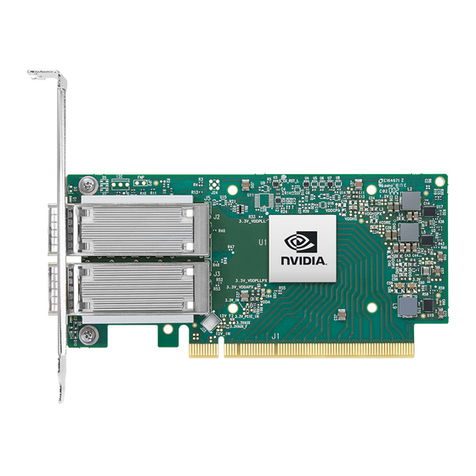
Nvidia Mellanox ConnectX-5 User manual

Exported on Dec/05/2023 09:29 AM
NVIDIA ConnectX-5 Ethernet Adapter Cards
for OCP Spec 3.0 User Manual

2
Table of Contents
Introduction..................................................................................... 8
Features and Benefits ...............................................................................9
Operating Systems/Distributions ................................................................ 11
Connectivity ........................................................................................ 11
Interfaces ......................................................................................12
Ethernet SFP28 and QSFP28 Interfaces ......................................................... 12
Networking Port LEDS Interface ................................................................. 12
PCI Express Interface.............................................................................. 13
FRU EEPROM ........................................................................................ 13
Heat Sink Interface ................................................................................ 13
SMBus Interface .................................................................................... 13
Voltage Regulators ................................................................................. 14
CPLD Interface ..................................................................................... 14
Thermal Sensors 1 ................................................................................. 14
Hardware Installation ........................................................................15
Safety Warnings .................................................................................... 15
Installation Procedure Overview................................................................. 16
System Requirements ............................................................................. 17
Hardware Requirements ...................................................................... 17
Airflow Requirements ......................................................................... 17
Software Requirements ....................................................................... 17
Safety Precautions ................................................................................. 18
Pre-Installation Checklist ......................................................................... 18
OCP 3.0 Bracket Replacement Instructions .................................................... 18
OCP 3.0 Adapter Card Installation Instructions................................................ 20
Cables and Modules................................................................................ 21
Identifying the Card in Your System............................................................. 22
Cards Extraction Instructions .................................................................... 23
Driver Installation.............................................................................24
Windows Driver Installation ...................................................................... 24
Software Requirements ....................................................................... 24
Downloading WinOF-2 Driver................................................................. 24

3
Installing WinOF-2 Driver ..................................................................... 25
Firmware Upgrade ............................................................................. 32
Linux Driver Installation .......................................................................... 32
Prerequisites.................................................................................... 32
Downloading NVIDIA OFED .................................................................... 32
Installing MLNX_OFED ......................................................................... 33
Driver Load Upon System Boot............................................................... 38
Additional Installation Procedures .......................................................... 40
Performance Tuning ........................................................................... 46
VMware Driver Installation ....................................................................... 46
Software Requirements ....................................................................... 46
Installing NATIVE ESXi Driver for VMware vSphere ........................................ 46
Removing Earlier NVIDIA Drivers ............................................................. 47
Firmware Programming ....................................................................... 47
Updating Adapter Firmware .................................................................48
Troubleshooting ...............................................................................49
General Troubleshooting .......................................................................... 49
Linux Troubleshooting ............................................................................. 50
Windows Troubleshooting......................................................................... 50
Specifications..................................................................................51
MCX562A-ACAI / MCX562A-ACAB Specifications............................................... 51
MCX566A-CCAI Specifications .................................................................... 53
MCX565A-CCAB Specifications ................................................................... 54
MCX566A-CDAB / MCX566A-CDAI Specifications............................................... 55
MCX565M-CDAI / MCX565M-CDAB Specifications .............................................. 57
Board Mechanical Drawing and Dimensions.................................................... 58
Brackets Mechanical Drawing and Dimensions ................................................ 59
Monitoring......................................................................................60
Thermal Sensors.................................................................................... 60
Adapter Card Heatsink ............................................................................ 60
Finding MAC and Serial Number on the Adapter Card ...................................61
Document Revision History ..................................................................62

4
About This Manual
This is the User Guide for NVIDIA® Ethernet adapter cards based on the ConnectX®-5 integrated
circuit device for Open Compute Project Spec 3.0. These adapters' connectivity provide the highest
performing low latency and most flexible interconnect solution for PCI Express Gen 3.0/4.0 servers
used in Enterprise Data Centers and High-Performance Computing environments.
EOL'd (End of Life) Ordering Part Numbers
The table below provides the ordering part numbers (OPN) for ConnectX-5 Ex and ConnectX-5
Ethernet adapter cards for OCP Spec 3.0.
IC in Use NVIDIA SKU Legacy OPN Marketing Description
ConnectX®-5 900-9X523-0053-SI1 MCX562A-ACAI ConnectX®-5 EN network interface
card for OCP 3.0, with host
management, 25GbE Dual-port
SFP28, PCIe3.0 x16, Internal Lock
bracket
900-9X523-0053-SB1 MCX562A-ACAB ConnectX®-5 EN network interface
card for OCP 3.0, with host
management, 25GbE Dual-port
SFP28, PCIe3.0 x16, Thumbscrew
(Pull Tab) bracket
900-9X556-0056-SI1 MCX566A-CCAI ConnectX®-5 EN network interface
card for OCP 3.0, with host
management, 100GbE Dual-port
QSFP28, PCIe3.0 x16, Internal Lock
bracket
900-9X556-0016-SB0 MCX565A-CCAB ConnectX®-5 EN network interface
card for OCP 3.0, with host
management, 100GbE Single-port
QSFP28, PCIe3.0 x16, Thumbscrew
(Pull Tab) bracket
ConnectX®-5 Ex900-9X556-0055-MI0 MCX566M-GDAI ConnectX®-5 Ex EN network
interface card for OCP 3.0 with
Multi-Host or Socket Direct and host
management, 50GbE Dual-port
QSFP28, PCIe 4.0/3.0 x16, Internal
Lock bracket
900-9X556-0016-MI0 MCX565M-CDAI ConnectX®-5 Ex EN network
interface card for OCP 3.0, with
Multi-Host or Socket Direct and host
management, 100GbE Single-port
QSFP28, PCIe4.0 x16, Internal Lock
bracket
900-9X556-0016-MB0 MCX565M-CDAB ConnectX®-5 Ex EN network
interface card for OCP 3.0, with
Multi-Host or Socket Direct and host
management, 100GbE Single-port
QSFP28, PCIe4.0 x16, Thumbscrew
(Pull Tab) bracket
900-9X556-0056-SI0 MCX566A-CDAI ConnectX®-5 Ex EN network
interface card for OCP 3.0 with host
management, 100GbE Dual-port
QSFP28, PCIe4.0 x16, Internal Lock
bracket
5
•
•
IC in Use NVIDIA SKU Legacy OPN Marketing Description
900-9X556-0056-SB0 MCX566A-CDAB ConnectX®-5 Ex EN network
interface card for OCP 3.0, with host
management, 100GbE Dual-port
QSFP28, PCIe4.0 x16, Thumbscrew
(Pull Tab) bracket
Intended Audience
This manual is intended for the installer and user of these cards.The manual assumes basic
familiarity with Ethernet network and architecture specifications.
Technical Support
Customers who purchased NVIDIAproducts directly from NVIDIA are invited to contact usthrough
the following methods:
URL:https://www.nvidia.com> Support
E-mail:[email protected]
Customers who purchased NVIDIA Global Support Services, please see your contract for details
regarding Technical Support.
Customers who purchased NVIDIA products through an NVIDIA-approved reseller should first seek
assistance through their reseller.
Related Documentation
NVIDIAMLNX_OFED for Linux User
Manual and Release Notes
User Manual and Release Notesdescribing MLNx_OFEDfeatures,
performance, band diagnostic, tools content and configuration.
SeeNVIDIA MLNX_OFED for Linux Documentation.
WinOF-2 for WindowsUser Manual and
Release Notes
User Manual describing WinOF-2 features, performance,
Ethernet diagnostic, tools content and configuration.
SeeWinOF-2 for Windows Documentation.
NVIDIA VMware for Ethernet User Manual
and Release Notes
User Manual describing the various components of the NVIDIA
ConnectX® NATIVE ESXi stack.SeeVMware® ESXi
Documentation.
NVIDIA Firmware Utility (mlxup) User
Manual and Release Notes
NVIDIA firmware update and query utility used to update the
firmware.SeeNVIDIA Firmware Utility (mlxup) Documentation.
NVIDIA Firmware Tools (MFT) User
Manual
User Manual describing the set of MFT firmware management
tools for a single node. SeeMFT User Manual.
Open Compute Project 3.0
Specifications
https://www.opencompute.org/
IEEE Std 802.3 Specification IEEE Ethernet Specifications
PCI Express Specifications Industry Standard PCI Express Base and Card Electromechanical
Specifications. Refer toPCI-SIG Specifications.

6
NVIDIAMLNX_OFED for Linux User
Manual and Release Notes
User Manual and Release Notesdescribing MLNx_OFEDfeatures,
performance, band diagnostic, tools content and configuration.
SeeNVIDIA MLNX_OFED for Linux Documentation.
LinkX Interconnect Solutions LinkX Ethernet cables and transceivers are designed to
maximize the performance of High-Performance Computing
networks, requiring high-bandwidth, low-latency connections
between compute nodes and switch nodes.NVIDIA offers one of
the industry’s broadest portfolio of 40GbE, 56GbE, 100GbE,
200GbE and400GbE cables, includingDirect Attach Copper
cables (DACs), copper splitter cables, Active Optical Cables
(AOCs) and transceivers in a wide range of lengths from 0.5m
to 10km. In addition to meeting Ethernetstandards, NVIDIA
tests every product in an end-to-end environment ensuring a
Bit Error Rate of less than 1E-15.Read more atLinkX Cables
and Transceivers.

7
Document Conventions
When discussing memory sizes, MB and MBytes are used in this document to mean size in mega
Bytes. The use of Mb or Mbits (small b) indicates size in mega bits. In this document PCIe is used to
mean PCI Express.

8
1.
2.
Introduction
This is the User Guide for Ethernet adapter cards based on the ConnectX®-5 and ConnectX®-5 Ex
integrated circuit device for OCP Spec 3.0. These adapters connectivity provide the highest
performing low latency and most flexible interconnect solution for PCI Express Gen 3.0/4.0 servers
used in Enterprise Data Centers and High-Performance Computing environments.
Important Notes:
ConnectX-5 OCP 3.0 cards were tested for Shock & Vibe in accordance with NVIDIA
specifications and setup, as the OCPspec3.0 available at that time did not contain any S&V
definitions. A newer version of the OCP spec 3.0 has defined S&V specifications and NVIDIA is
in the midst of retesting these cards to comply with OCP spec 3.0.
In some of the OCP 3.0 cards, the insertion force that is required to install the card into a
particular PCI connector may exceed the maximum insertion force that is allowed by the
connector’s spec.NVIDIA is updating the OCP 3.0 cards to ensure the proper insertion
process.
The following tables provide the ordering part number, port speed, number of ports, and PCI Express
speed per ConnectX-5 and ConnectX-5 ExOPNs.
ConnectX-5 Ex Adapter Cards for OCP 3.0
Part Number MCX566M-
GDAI
MCX565M-
CDAI
MCX565M-
CDAB
MCX566A-
CDAI
MCX566A-CDAB
Ethernet Data Rate Up to 50Gb/s Up to 100Gb/s Up to 100Gb/s Up to 100Gb/s Up to 100Gb/s
Network Connector
Type
x2 QSFP28 ports x1 QSFP28 port x1 QSFP28 port x2 QSFP28 ports x2 QSFP28 ports
PCI Express
Connectors
PCIe Gen 3.0 / 4.0 x16 (a), (b)
SERDES @ 8.0GT/s / 16.0GT/s
Bracket Internal-Lock
Bracket
Internal-Lock
Bracket
Pull-tab Bracket Internal-Lock
Bracket
Pull-tab bracket
Host Management ✔ ✔ ✔ ✔ ✔
Multi-Host/ Socket
Direct
✔ ✔ ✔ NA NA
IC Part Number MT28804A0-
FCCF-CEM
MT28804A0-
FCCF-CEM
MT28804A0-
FCCF-CEM
MT28808A0-
FCCF-CE
MT28808A0-
FCCF-CE
Device ID 4121 for Physical Function (PF)
4122 for Virtual Function (VF)
Form Factor
Dimensions
Small Form Factor (SFF)
4.52in. x 2.99in. (115mm x 76mm)
RoHS RoHS Compliant
ConnectX-5 Adapter Cards for OCP 3.0

9
Part Number MCX562A-ACAI MCX562A-ACAB MCX566A-CCAI MCX565A-CCAB
Ethernet Data Rate Up to 25Gb/s Up to 25Gb/s Up to 100Gb/s Up to 100Gb/s
Network Connector Type x2 SFP28 ports x2 SFP28 ports x2 QSFP28 ports x1 QSFP28 ports
PCI Express Connectors PCIe Gen 3.0 x16
SERDES @ 8.0GT/s
Bracket Internal-Lock
Bracket
Pull-tab Bracket Internal-Lock Bracket Pull-tab Bracket
Host Management ✔ ✔ ✔ ✔
IC Part Number MT27808A0-FCCF-
AE
MT27808A0-FCCF-
AE
MT27808A0-FCCF-CE MT27808A0-FCCF-CE
Device ID 4119 for Physical Function (PF)
4120 for Virtual Function (VF)
Form Factor Dimensions Small Form Factor (SFF)
4.52in. x 2.99in. (115mm x 76mm)
RoHS RoHS Compliant
a. PCIe 4.0 x16 bus can supply a maximum bandwidth of 256Gb/s (=16 *16GT/s, including overhead),
and can support 200Gb/s when both network ports of the card run at 100Gb/s.
b.TheGen4.0 cards have been tested and certified with PCIe 3.0 servers. PCIe 4.0 interface will be
tested when servers with Gen 4.0 support become available.
For more detailed information seeSpecifications.
Features and Benefits
Feature Description
PCI Express
(PCIe)
Uses PCIe Gen 3.0 (8GT/s) and Gen 4.0 (16GT/s) through an x8 or x16 edge connector. Gen 1.1
and 2.0 compatible.
Up to 100
Gigabit
Ethernet
NVIDIA adapters comply with the following IEEE 802.3 standards:
• 100GbE/ 50GbE / 40GbE / 25GbE / 10GbE / 1GbE
• IEEE 802.3bj, 802.3bm 100 Gigabit Ethernet
• IEEE 802.3by, Ethernet Consortium25, 50 Gigabit Ethernet, supporting all FEC modes
• IEEE 802.3ba 40 Gigabit Ethernet
• IEEE 802.3by 25 Gigabit Ethernet
• IEEE 802.3ae 10 Gigabit Ethernet
• IEEE 802.3ap based auto-negotiation and KR startup
• Proprietary Ethernet protocols (20/40GBASE-R2, 50GBASE-R4)
• IEEE 802.3ad, 802.1AX Link Aggregation
• IEEE 802.1Q, 802.1P VLAN tags and priority
• IEEE 802.1Qau (QCN)
• Congestion Notification
• IEEE 802.1Qaz (ETS)
• IEEE 802.1Qbb (PFC)
• IEEE 802.1Qbg
• IEEE 1588v2
• Jumbo frame support (9.6KB)
This section describes hardware features and capabilities. Please refer to the relevant
driver and/or firmware release notes for feature availability.

10
•
•
Feature Description
Memory EEPROM - The EEPROM capacity is 32Kbit.FRU I2C address is (0x50) and is accessible
through the PCIe SMBus (Note: Address 0x58 is reserved.)
SPI - includes 128Mb SPI Flash device (by WINBOND-NUVOTON).
Overlay
Networks
In order to better scale their networks, data center operators often create overlay networks that
carry traffic from individual virtual machines over logical tunnels in encapsulated formats such
as NVGRE and VXLAN. While this solves network scalability issues, it hides the TCP packet from
the hardware offloading engines, placing higher loads on the host CPU. ConnectX-5 effectively
addresses this by providing advanced NVGRE and VXLAN hardware offloading engines that
encapsulate and de-capsulate the overlay protocol.
RDMA and
RDMA
overConver
ged
Ethernet
(RoCE)
ConnectX-5, utilizing IBTA RDMA (Remote Data Memory Access) and RoCE (RDMA over Converged
Ethernet) technology, delivers low-latency and high-performance over Band and Ethernet
networks. Leveraging data center bridging (DCB) capabilities as well as ConnectX-5 advanced
congestion control hardware mechanisms, RoCE provides efficient low-latency RDMA services
over Layer 2 and Layer 3 networks.
NVIDIA
PeerDirect™
PeerDirect™ communication provides high-efficiency RDMA access by eliminating unnecessary
internal data copies between components on the PCIe bus (for example, from GPU to CPU), and
therefore significantly reduces application run time. ConnectX-5 advanced acceleration
technology enables higher cluster efficiency and scalability to tens of thousands of nodes.
CPU Offload Adapter functionality enabling reduced CPU overhead allowing more available CPU for
computation tasks.
Open vSwitch (OVS) offload using ASAP2(TM)
• Flexible match-action flow tables
• Tunneling encapsulation/decapsulation
Quality of
Service
(QoS)
Support for port-based Quality of Service enabling various application requirements for latency
and SLA.
Hardware-
based I/
OVirtualiza
tion
ConnectX-5 provides dedicated adapter resources and guaranteed isolation and protection for
virtual machines within the server.
Storage
Acceleratio
n
A consolidated compute and storage network achieves significant cost-performance advantages
over multi-fabric networks. Standard block and file access protocols can leverage RDMA for high-
performance storage access.
• NVMe over Fabric offloads for target machine
SR-IOV ConnectX-5 SR-IOV technology provides dedicated adapter resources and guaranteed isolation
and protection for virtual machines (VM) within the server.
NC-SI over
RMII
The adapter supports a slave Network Controller Sideband Interface (NC-SI) that can be
connected to a BMC.
High-
Performanc
eAccelerati
ons
• Tag Matching and Rendezvous Offloads
• Adaptive Routing on Reliable Transport
• Burst Buffer Offloads for Background Checkpointing
Host
Managemen
t
Technology
NVIDIA’s host management technology for standard and multi-host platforms optimizes board
management and power, performance and firmware update management via NC-SI, MCTP over
SMBus and MCTP over PCIe, as well as PLDM for Monitor and Control DSP0248 and PLDM for
Firmware Update DSP0267.

11
•
•
•
•
•
•
•
•
•
Feature Description
Multi-Host
Technology
NVIDIA Multi-Host™ technology, when enabled, allows multiple hosts to be connected into a
single adapter by separating the PCIe interface into multiple and independent interfaces. By
Using NVIDIA Multi Host™, ConnectX-5 lowers the total cost of ownership (TCO) in the data center
by reducing CAPEX (cables, NICs, and switch port expenses), and by reducing OPEX by cutting
down on switch port management and overall power usage. With NVIDIA Multi-Host™ technology
powered by a shared buffer architecture, connection-tracking offloads, and RoCE enhancements,
ConnectX-5 offers an extremely flexible solution for today’s demanding data center and cloud
application.
NVIDIA
Socket
Direct™
NVIDIA Socket Direct technology brings improved performance to multi-socket servers by
enabling direct access from each CPU in a multi-socket server to the network through its
dedicated PCIe interface. With this type of configuration, each CPU connects directly to the
network; this enables the interconnect to bypass a QPI (UPI) and the other CPU, optimizing
performance and improving latency. CPU utilization improves as each CPU handles only its own
traffic, and not the traffic from the other CPU. NVIDIA’s OCP 3.0 cards include native support for
socket direct technology for multi-socket servers and can support up to 4 CPU sockets.
Wake-on-
LAN (WoL)
Supported
Reset-on-
Lan (RoL)
Supported
Operating Systems/Distributions
RHEL/CentOS
Windows
FreeBSD
VMware
OpenFabrics Enterprise Distribution (OFED)
OpenFabrics Windows Distribution (WinOF-2)
Connectivity
Interoperable with 1/10/25/40/50/100Gb/s Ethernet switches
Passive copper cable with ESD protection
Powered connectors for optical and active cable support

12
•
•
•
Interfaces
Ethernet SFP28 and QSFP28 Interfaces
The network ports of the ConnectX®-5 adapter card are compliant with the IEEE 802.3 Ethernet
standards listed inFeatures and Benefits. Ethernet traffic is transmitted through the SFP28/QSFP28
connectors on the adaptercard.
Networking Port LEDS Interface
There are two I/O LEDs, LED0 and LED1, per port to indicate speed and link status. LED0 is a bicolor
(Yellow and Green) LED and LED1 is a single color (Green) LED.
Link Indications
LED and State Description
1Hz blinking Yellow Beacon command for locating the adapter card.
4Hz blinking Yellow Indicates an error with the link. The error can be one of the
following:
Error Type Description LED Behavior
I2C I2C access to the
networking ports fails
Blinks until the error
is fixed
Over-current Over-current condition
of the networking ports
Blinks until the error
is fixed
LED0 -
Link Speed
A constant Green indicates a link withthe maximum
networking speed.
A constant Yellow indicates a link withless than the
maximum networking speed
If LED0 is off, then the link has not been established.
The adapter card includes special circuits to protect from ESD shocks to the card/server
when plugging copper cables.

13
•
•
LED and State Description
LED1 -
Activity
A blinking Green indicates a valid link with data transfer.
If LED1 is off, then there is no activity
PCI Express Interface
The table below describes the supported PCIe interface in ConnectX-5 and ConnectX-5 Ex adapter
cards.
IC Model Supported PCIe Interface Features
ConnectX-5 PCIe Gen 3.0 (1.1 and 2.0 compatible)
through x16 edge connectors
Link Rates: 2.5. 5.0 or 8.0GT/s.
Auto Negotiation to: x16, x8, x4, x2 or
x1.
Support for MSI/MSI-X mechanisms.
ConnectX-5 Ex PCIe Gen 3.0/4.0 (1.1 and 2.0 compatible)
through x16 edge connectors
Link Rates: 2.5. 5.0, 8.0 or 16.0GT/s.
Auto Negotiation to: x16, x8, x4, x2 or
x1.
Support for MSI/MSI-X mechanisms.
FRU EEPROM
FRU EEPROM allows the baseboard to identify different types of Mezzanine cards. MEZZ FRU EEPROM
is accessible through MEZZ_SMCLK and MEZZ_SMDATA (Connector A18 and A19). MEZZ FRU EEPROM
address is 0xA2 and its capacity is 4Kb.
Heat Sink Interface
A heatsink is attached to the ConnectX-5 IC in order to dissipate the heat from the ConnectX- 5 IC. It
is attached either by using four spring-loaded push pins that insert into four mounting holes.
ConnectX-5 IC has a thermal shutdown safety mechanism which automatically shuts down the
ConnectX-5 card in cases of high-temperature event, improper thermal coupling or heatsink
removal.
SMBus Interface
ConnectX-6 technology maintains support for manageability through a BMC. ConnectX-6 OCP 3.0
adapter can be connected to a BMC using MCTP over SMBus or MCTP over PCIe protocols as if it is a
standard NVIDIA OCP 3.0 adapter. For configuring the adapter for the specific manageability solution
in use by the server, please contact NVIDIA Support.

14
Voltage Regulators
The voltage regulator power is derived from the OCP 3.0 edge connector 12V and 3.3V supply pins.
These voltage supply pins feed onboard regulators that provide the necessary power to the various
components on the card.
CPLD Interface
The adapter card incorporates a CPLD device that controls the networking port LEDs and the scan
chain. It draws its power supply from 3.3V_EDGE.
Thermal Sensors 1
Unable to render include or excerpt-include. Could not retrieve page.

15
•
•
Hardware Installation
Installation and initialization of ConnectX-5 adapter cards for OCP Spec 3.0 require attention to the
mechanical attributes, power specifications, and precautions for electronic equipment.
Safety Warnings
Note that not all warnings are relevant to all models.
General Installation Instructions
Read all installation instructions before connecting the equipment to the power source.
Jewelry Removal Warning
Before you install or remove equipment that is connected to power lines, remove jewelry such as
bracelets, necklaces, rings, watches, and so on. Metal objects heat up when connected to power and
ground and can meltdown, causing serious burns and/or welding the metal object to the terminals.
Over-temperature
This equipment should not be operated in an area with an ambient temperature exceeding the
maximum recommended: 55°C (131°F).An airflow of 200LFM at this maximum ambient
temperature is required for HCA cards and NICs.To guarantee proper airflow, allow at least 8cm (3
inches) of clearance around the ventilation openings.
During Lightning - Electrical Hazard
During periods of lightning activity, do not work on the equipment or connect or disconnect cables.
Copper Cable Connecting/Disconnecting
Some copper cables are heavy and not flexible, as such, they should be carefully attached to or
detached from the connectors. Refer to the cable manufacturer for special warnings and
instructions.
Equipment Installation
This equipment should be installed, replaced, or serviced only by trained and qualified personnel.
Equipment Disposal
The disposal of this equipment should be in accordance to all national laws and regulations.
Local and National Electrical Codes
This equipment should be installed in compliance with local and national electrical codes.
Hazardous Radiation Exposure
Caution – Use of controls or adjustment or performance of procedures other than
those specified herein may result in hazardous radiation exposure.For products with
optical ports.
CLASS 1 LASER PRODUCT and reference to the most recent laser standards:
IEC 60 825-1:1993 + A1:1997 + A2:2001 and EN 60825-1:1994+A1:1996+ A2:20
Safety warnings are provided here in the English language. For safety warnings in other
languages, refer to the Adapter Installation Safety Instructions.

16
Installation Procedure Overview
The installation procedure of ConnectX-5 adapter cards for OCP Spec 3.0 involves the following
steps:
Step Procedure Direct Link
1Check the system’s hardware and software requirements. Refer to System Requirements
2 Pay attention to the airflow consideration within the host
system
Refer to Airflow Requirements
3 Follow the safety precautions Refer to Safety Precautions
4 Follow the pre-installation checklist Refer to Pre-Installation Checklist
5 (Optional) Replace the assembled OCP 3.0 bracket with the
desired form factor bracket
Refer toOCP 3.0 Bracket Replacement
Instructions
6 Install ConnectX-5 adapter card in the system
according to the retention mechanism on the card
Refer to Thumbscrew (Pull-tab) Cards
Refer to Internal Lock Cards
7 Connect cables or modules to the card Refer to Cables and Modules
8 Identify ConnectX-5 adapter card in the system Refer to Identify the Card in Your
System

17
•
•
System Requirements
Hardware Requirements
A system with a PCI Express x16 slot for OCP spec 3.0 is required for installing the card.
Airflow Requirements
ConnectX-5 adapter cards are offered with two airflow patterns: from the heatsink to the network
ports, and vice versa, as shown below.
Please refer to the "Specifications" chapter for airflow numbers for each specific card model.
Heatsink-to-port AirflowDirection Port-to-heatsink Airflow Direction
Software Requirements
See Operating Systems/Distributions section under the Introduction section.
Software Stacks -NVIDIA OpenFabric software package MLNX_OFED for Linux, WinOF-2 for
Windows, and VMware. See the Driver Installation section.
Unless otherwise specified,NVIDIA products are designed to work in an environmentally
controlled data center with low levels of gaseous and dust (particulate) contamination.
The operating environment should meet severity level G1 as per ISA 71.04 for gaseous
contamination and ISO 14644-1 class 8 for cleanliness level.
For proper operation and performance, please make sure to use a PCIe slot with a
corresponding bus width and that can supply sufficient power to your card. Refer to the
Specifications section of the manual for more power requirements.
All cards in the system should be planned with the same airflow direction.

18
1.
2.
3.
4.
1.
2.
•
•
Safety Precautions
Remove any metallic objects from your hands and wrists.
Make sure to use only insulated tools.
Verify that the system is powered off and is unplugged.
It is strongly recommended to use an ESD strap or other antistatic devices.
Pre-Installation Checklist
Unpack the ConnectX-5 adapter card.
Unpack and remove the ConnectX-5 card. Check the parts for visible damage that may have
occurred during shipping. Please note that the cards must be placed on an antistatic surface.
Shut down your system if active:
Turn off the power to the system, and disconnect the power cord. Refer to the system
documentation for instructions. Before you install the ConnectX-5 card, make sure that the
system is disconnected from power.
OCP 3.0 Bracket Replacement Instructions
The OCP 3.0 adapter card is shipped assembled either with a thumbscrew (pull-tab) bracket, an
internal-lock bracket, or an ejector-latch bracket. If this form factor is suitable for your
requirements, you can skip the remainder of this section and move to Installation Instructions. If
you need to replace the assembled OCP 3.0 bracket with a different form-factor bracket, please
follow the instructions in this section.
To replace the bracket you will need the following parts:
The new bracket of the desired form factor.
The screws supplied with the new bracket kit.
•
•
•
•
The adapter is being installed in a system that operates with voltages that can be lethal.
Before opening the case of the system, observe the following precautions to avoid injury
and prevent damage to system components.
Remove any metallic objects from your hands and wrists.
Make sure to use only insulated tools.
Verify that the system is powered off and is unplugged.
It is strongly recommended to use an ESD strap or other antistatic devices.
Please note that if the card is removed hastily from the antistatic bag, the plastic
ziplock may harm the EMI fingers on the networking connector. Carefully remove the
card from the antistatic bag to avoid damaging the EMI fingers.
Due to risk of damaging the EMI gasket, it is not recommended to replace the bracket more
than three times.

19
•
1.
2.
3.
1.
The required torx tool type as specified in the instructions.
Removing the Existing Bracket
Using the torx tool type listed in the below table, remove the screws according to the
instructions per OCP 3.0 bracket type.
Internal Lock Bracket Pull-tab (Thumbscrew) Bracket Ejector-Latch Bracket
Gently separate the bracket from the OCP 3.0 card.
Internal Lock Bracket Pull-tab Bracket Ejector-Latch Bracket
Save the two screws.
Installing the New Bracket
Assemble the new bracket onto the card.
Internal Lock Bracket Pull-tab Bracket Ejector-Latch Bracket
Be careful not to put stress on the LEDs on the adapter card.
Do not force the bracket onto the adapter card.

20
2.
3.
1.
2.
3.
Ensure that the insulator's front edge is beneath the bracket, as shown in the below figure.
Screw on the OCP 3.0 bracket with the supplied screws that came with the new bracket kit.
Use the specified torx tool type and apply the specified torque on the screws per bracket
form factor.
Internal Lock Bracket Pull-tab Bracket Ejector-Latch Bracket
Note that one screw is flat-head 90° screw and
the other is socket-head screw. Screw on the
different types of screws as shown in the below
illustration.
OCP 3.0 Adapter Card Installation Instructions
This section provides detailed instructions on how to install your adapter card in a system.The OCP
3.0 adapter card is shipped assembled either with an internal-lock, a pull-tab (thumbscrew), or an
ejector-latch bracket. Follow the below instructions depending on the card you have purchased.
Before installing the card, make sure that the system is off and the power cord is not
connected to the server. Please follow proper electrical grounding procedures.
Open the system case.
Align the card with the system rails.
The following figures are for illustration purposes only.
Other manuals for Mellanox ConnectX-5
5
This manual suits for next models
10
Table of contents
Other Nvidia Adapter manuals

Nvidia
Nvidia Mellanox ConnectX-5 User manual

Nvidia
Nvidia Mellanox ConnectX-6 Dx Series User manual

Nvidia
Nvidia 900-9X662-00 53-ST1 User manual

Nvidia
Nvidia Mellanox ConnectX-4 Lx User manual

Nvidia
Nvidia Mellanox ConnectX-4 Lx User manual

Nvidia
Nvidia Mellanox MCX621102ACADAT User manual

Nvidia
Nvidia QUADRO SLI HB BRIDGE User manual

Nvidia
Nvidia 900-9X4B0-0012-0T1 User manual

Nvidia
Nvidia Mellanox ConnectX-6 MCX651105A-EDAT User manual

Nvidia
Nvidia Mellanox ConnectX-6 Dx Series User manual