7
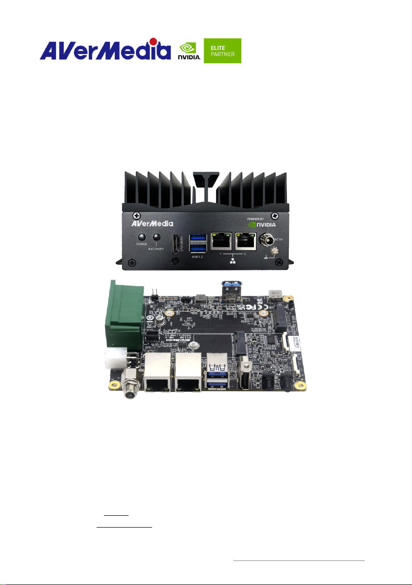
D115W Series User Manual https://www.avermedia.com/professional/
Trademark Acknowledgement
AVerMedia acknowledges all the trademarks, registered trademarks, and/or copyrights referred to
in this document as the property of their respective owners. Not listing all possible trademarks or
copyright acknowledgments does not constitute the lack of acknowledgment to the rightful
owners of the trademarks and copyrights mentioned in this document.
ESD Warning
Electronic components and circuits are sensitive to Electrostatic Discharge (ESD). When
handling any circuit board assemblies including AVerMedia products, it is highly recommended
that ESD safety precautions can be observed. ESD safe best practices can include, but are not
limited to the following ones.
1. Leave the circuit board in the antistatic package until it is ready to be installed.
2. Use a grounded wrist strap when handling the circuit board. At a minimum, you need to touch
a grounded metal object to dissipate any static charge, which may be present on you.
3. Avoid handling the circuit board in the carpeted areas.
4. Handle the board by the edges and avoid the contact with the components.
5. Only handle the circuit boards in ESD safe areas, which may include ESD floor and/or table
mats, wrist strap stations, and ESD safe lab coats.
Safety Precaution:
1. All cautions and warnings on the device should be noted.
2. For safety consideration, do NOT open the device if not a qualified service stuff.
3. Place the device on a solid surface during installation to prevent falls.
4. Keep the device away from humidity.
5. Do NOT leave this device in an un-controlled environment with temperatures beyond the
device’s permitted storage temperature to avoid damage.
6. All adaptors and cables supplied by AVerMedia are verified. Do NOT use any others not
supplied by AVerMedia to avoid any malfunction or fires.
7. Make sure the power source matches the power rating of the device.
8. Place the power cord where people cannot step on it. Do not put anything on the power cord.
9. Always completely disconnect the power while the device is not usage or idle for a long time.
10. Disconnect the device from any AC supply before cleaning. While cleaning, use a damp cloth
instead of liquid or spray detergents.
11. Make sure the device is installed near a power outlet and easy for accessible.
12. Do not cover the openings on the device to ensure optimal heat dissipation.