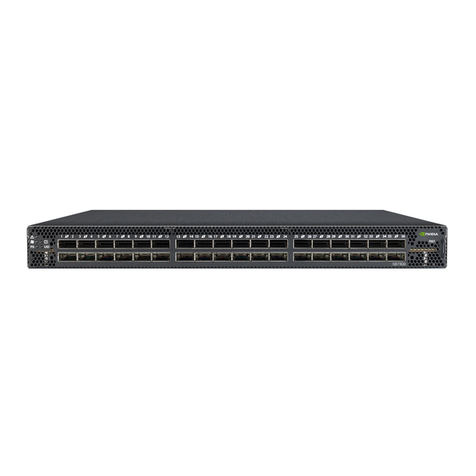
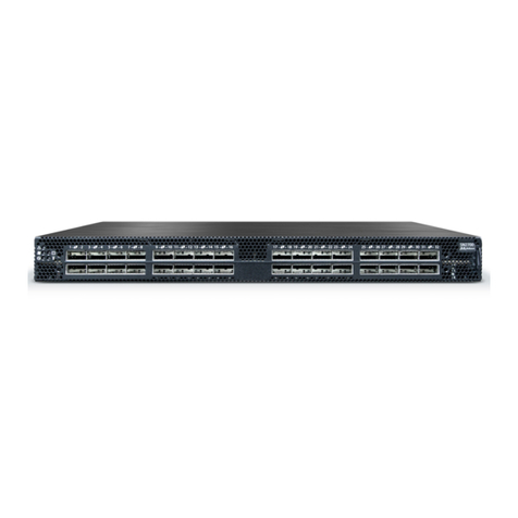
Nvidia Spectrum-3 SN4000 Series Instructions for use

Exported on Sep/19/2022 02:33 PM
NVIDIA Spectrum-3 SN4000 1U and 2U
Switch Systems Hardware User Manual
NVIDIA Spectrum-3 SN4000 1U and 2U Switch Systems Hardware User Manual, SN4700,
SN4600C, SN4600, SN4410

2
Table of Contents
Ordering Information .......................................................................... 5
SN4410 Ordering Part Numbers ....................................................................5
SN4600/SN4600C Ordering Part Numbers ........................................................5
SN4700 Ordering Part Numbers ....................................................................6
Introduction..................................................................................... 8
Speed and Switching Capabilities .................................................................9
Management Interfaces, PSUs and Fans ........................................................ 10
Features ............................................................................................. 10
Certifications ....................................................................................... 11
Installation.....................................................................................12
System Installation and Initialization ........................................................... 12
Safety Warnings .................................................................................... 13
Air Flow.............................................................................................. 13
Package Contents .................................................................................. 14
Mounting Options .................................................................................. 15
SN4600/SN4600C Fixed Rail Kit .................................................................. 15
Removing the System from the Rack........................................................ 21
SN4600/SN4600C Telescopic Rail Kit ............................................................ 21
Removing the System from the Rack........................................................ 26
SN4410/SN4700 Fixed Rail Kit.................................................................... 27
Cable Installation .................................................................................. 33
Splitter (Breakout) Cables and Adapters ................................................... 33
Initial Power On .................................................................................... 36
System Bring-Up.................................................................................... 38
Configuring Network Attributes Using NVIDIA Onyx (MLNX-OS) ......................... 38
Configuring Network Attributes Using Cumulus Linux .................................... 41
FRU Replacements ................................................................................. 41
Power Supplies ................................................................................. 42
Fans .............................................................................................. 43
Interfaces ......................................................................................45
Data Interfaces ..................................................................................... 45
RS232 (Console) .................................................................................... 47

3
Management ........................................................................................ 47
USB ................................................................................................... 47
Reset Button ........................................................................................ 47
Status and Port LEDs............................................................................... 48
LED Notifications................................................................................... 48
System Status LED ............................................................................. 48
Fan Status LED.................................................................................. 49
Power Supply Status LEDs..................................................................... 50
Unit Identification LED........................................................................ 51
Port LEDs ........................................................................................ 52
Inventory Information ............................................................................. 55
Software Management .......................................................................57
Software Upgrade.................................................................................. 57
NVIDIA Onyx (MLNX-OS) Software Upgrade................................................. 57
Switch Firmware Update...................................................................... 57
Cumulus Linux Software Upgrade ........................................................... 57
Troubleshooting ...............................................................................58
Specifications..................................................................................60
SN4410 Specifications ............................................................................. 60
SN4600/SN4600C Specifications ................................................................. 61
Appendixes.....................................................................................63
Accessory and Replacement Parts ............................................................... 63
Thermal Threshold Definitions................................................................... 64
Interface Specifications........................................................................... 64
Small Form Factors Specifications .......................................................... 64
USB Standard Specifications.................................................................. 64
RJ45 to DB9 Harness Pinout .................................................................. 65
Disassembly and Disposal ......................................................................... 65
Disassembly Procedure........................................................................ 65
Disposal.......................................................................................... 66
Document Revision History ..................................................................67

4
Relevant for Models: SN4410, SN4600/SN4600C and SN4700
About this Manual
This manual describes the installation and basic use of NVIDIA Ethernet switches based on the
NVIDIA® Spectrum®-3 ASIC.
Ordering Information
SeeOrdering Information.
Intended Audience
This manual is intended for IT managers and system administrators.
Related Documentation
Document Description
NVIDIA Onyx (MLNX-OS) User Manual This document contains information regarding the
configuration and management of the NVIDIA Onyx®
(MLNX-OS®) software. See https://www.nvidia.com/en-
us/networking/ethernet-switching/onyx/.
Cumulus Linux User Guide This document contains information regarding the
configuration and management of the Cumulus® Linux®
software. See https://docs.cumulusnetworks.com.
Open Network Install Environment (ONIE) Quick
Start Guide
See https://github.com/opencomputeproject/onie/wiki/
Quick-Start-Guide/.
Hands-on workshops Cumulus on-site/remote training:https://
academy.nvidia.com/en/cumulus-linux-boot-camp/
NVIDIA Onyx on-site/remote training:https://
academy.nvidia.com/en/course/onyx/?cm=242
On-site/remote services For any tailor-made service, contact nbu-services-
Revision History
A list of the changes made to this document are provided in Document Revision History.
This document is preliminary and subject to change.

5
Ordering Information
The following table lists ordering information for the available systems.
Please pay attention to the airflow direction when ordering your system. For more details, seeAir
Flow.
SN4410 Ordering Part Numbers
Syste
m
Mode
l
Part
Number
Legacy
Part
Number
Description
SN4410 920-9N312-00F
B-0C0
MSN4410-
WS2FC
NVIDIA Spectrum-3 based 400GbE 1U Open Ethernet Switch with
Cumulus Linux, 24 QSFP-DD28 and 8 QSFP-DD ports, 2 Power Supplies
(AC), x86 CPU, standard depth, P2C airflow, Rail Kit
920-9N312-00F
B-0N0
MSN4410-
WS2FO
NVIDIA Spectrum-3 based 400GbE 1U Open Ethernet Switch with ONIE,
24 QSFP-DD28 and 8 QSFP-DD ports, 2 Power Supplies (AC), x86 CPU,
standard depth, P2C airflow, Rail Kit
920-9N312-00R
B-0N0
MSN4410-
WS2RO
NVIDIA Spectrum-3 based 400GbE 1U Open Ethernet Switch with ONIE,
24 QSFP-DD28 and 8 QSFP-DD ports, 2 Power Supplies (AC), x86 CPU,
standard depth, C2P airflow, Rail Kit
SN4600/SN4600C Ordering Part Numbers
Syste
m
Model
Part Number Legacy
Part
Number
Description
SN4600 920-9N302-00F
A-0C0 MSN4600-
VS2FC
NVIDIA Spectrum-3 based 200GbE 2U Open Ethernet Switch with
Cumulus Linux, 64 QSFP56 ports, 2 Power Supplies (AC), x86 CPU,
standard depth, P2C airflow, Rail Kit
920-9N302-00R
A-0C0
MSN4600-
VS2RC
NVIDIA Spectrum-3 based 200GbE 2U Open Ethernet Switch with
Cumulus Linux, 64 QSFP56 ports, 2 Power Supplies (AC), x86 CPU,
standard depth, C2P airflow, Rail Kit
920-9N302-00R
A-0N0
MSN4600-
VS2RO
NVIDIA Spectrum-3 based 200GbE 2U Open Ethernet Switch with
ONIE, 64 QSFP56 ports, 2 Power Supplies (AC), x86 CPU, standard
depth, C2P airflow, Rail Kit
This document is preliminary and subject to change.

6
Syste
m
Model
Part Number Legacy
Part
Number
Description
920-9N302-00F
A-0N0
MSN4600-
VS2FO NVIDIA Spectrum-3 based 200GbE 2U Open Ethernet Switch with
ONIE, 64 QSFP56 ports, 2 Power Supplies (AC), x86 CPU, standard
depth, P2C airflow, Rail Kit
SN4600C
920-9N302-00F
7-0X0 MSN4600-
CS2F
NVIDIA Spectrum-3 based 100GbE 2U Open Ethernet Switch with
Onyx, 64 QSFP28 ports, 2 Power Supplies (AC), x86 CPU, standard
depth, P2C airflow, Rail Kit
920-9N302-00R
7-0X0
MSN4600-
CS2R
NVIDIA Spectrum-3 based 100GbE 2U Open Ethernet Switch with
Onyx, 64 QSFP28 ports, 2 Power Supplies (AC), x86 CPU, standard
depth, C2P airflow, Rail Kit
920-9N302-00F
7-0C2
MSN4600-
CS2FC NVIDIA Spectrum-3 based 100GbE 2U Open Ethernet Switch with
Cumulus Linux, 64 QSFP28 ports, 2 Power Supplies (AC), x86 CPU,
standard depth, P2C airflow, Rail Kit
920-9N302-00R
7-0C0
MSN4600-
CS2RC
NVIDIA Spectrum-3 based 100GbE 2U Open Ethernet Switch with
Cumulus Linux, 64 QSFP28 ports, 2 Power Supplies (AC), x86 CPU,
standard depth, C2P airflow, Rail Kit
920-9N302-00F
7-0N0
MSN4600-
CS2FO NVIDIA Spectrum-3 based 100GbE 2U Open Ethernet Switch with
ONIE, 64 QSFP28 ports, 2 Power Supplies (AC), x86 CPU, standard
depth, P2C airflow, Rail Kit
920-9N302-00R
7-0N0
MSN4600-
CS2RO
NVIDIA Spectrum-3 based 100GbE 2U Open Ethernet Switch with
ONIE, 64 QSFP28 ports, 2 Power Supplies (AC), x86 CPU, standard
depth, C2P airflow, Rail Kit
SN4700 Ordering Part Numbers
Syste
m
Model
Part
Number
Legacy
Part
Number
Description
SN4700
920-9N301-00F
B-0X0
MSN4700-
WS2F NVIDIA Spectrum-3 based 400GbE 1U Open Ethernet Switch with
Onyx, 32 QSFPDD ports, 2 Power Supplies (AC), x86 CPU, standard
depth, P2C airflow, Rail Kit
920-9N301-00
RB-0X0
MSN4700-
WS2R NVIDIA Spectrum-3 based 400GbE 1U Open Ethernet Switch with
Onyx, 32 QSFPDD ports, 2 Power Supplies (AC), x86 CPU, standard
depth, C2P airflow, Rail Kit
7
Syste
m
Model
Part
Number
Legacy
Part
Number
Description
920-9N301-00F
B-0C0
MSN4700-
WS2FC NVIDIA Spectrum-3 based 400GbE 1U Open Ethernet Switch with
Cumulus Linux, 32 QSFPDD ports, 2 Power Supplies (AC), x86 CPU,
standard depth, P2C airflow, Rail Kit
920-9N301-00
RB-0C0
MSN4700-
WS2RC NVIDIA Spectrum-3 based 400GbE 1U Open Ethernet Switch with
Cumulus Linux, 32 QSFPDD ports, 2 Power Supplies (AC), x86 CPU,
standard depth, C2P airflow, Rail Kit

920-9N301-00F
B-0N0
MSN4700-
WS2FO
NVIDIA Spectrum-3 based 400GbE 1U Open Ethernet Switch with
ONIE, 32 QSFPDD ports, 2 Power Supplies (AC), x86 CPU, standard
depth, P2C airflow, Rail Kit
920-9N301-00
RB-0N0
MSN4700-
WS2RO NVIDIA Spectrum-3 based 400GbE 1U Open Ethernet Switch with
ONIE, 32 QSFPDD ports, 2 Power Supplies (AC), x86 CPU, standard
depth, C2P airflow, Rail Kit

8
Introduction
The SN4000 series switches are the 4th generation of NVIDIA Spectrum® switches, purpose-built for
leaf/spine/super-spine datacenter applications. Allowing maximum flexibility, SN4000 series
provides port speeds spanning from 1GbE to 400GbE, and a port density that enables full rack
connectivity to any server at any speed. In addition, the uplink ports allow a variety of blocking
ratios to suit any application requirement. The SN4000 series is ideal for building wire-speed and
cloud-scale layer-2 and layer-3 networks. The SN4000 platforms deliver high performance,
consistent low latency along with support for advanced software defined networking features,
making it the ideal choice for web scale IT, cloud,
hyperconverged storage and data analytics applications.
Open Ethernet breaks the paradigm of traditional switch systems, eliminating vendor lock-in.
Instead of forcing network operators to use the specific software that is provided by the switch
vendor, Open Ethernet offers the flexibility to use a choice of operating systems on top of Ethernet
switches, thereby re-gaining control of the network, and optimizing utilization, efficiency and
overall return on investment. Open Ethernet adopts the same principles as standard open solutions
for servers and storage, and applies them to the world of networking infrastructure. It encourages
an ecosystem of open source, standard network solutions. These solutions can then be easily
deployed into the modern data center across network equipment that eases management and
ensures full interoperability. With a range of system form factors, and a rich software ecosystem,
SN4000 series allows you to pick and choose the right components for your data center.
NVIDIA SN4000 series platforms are based on the high-performance NVIDIA Spectrum-3 ASIC with a
switching capacity of 12.8 Tb/s. SN4000 platforms are available in a range of configurations, each
delivering high performance combined with feature-rich layer 2 and layer 3 forwarding, ideally
suited for both top-of-rack leaf and fixed configuration spines. The NVIDIA SN4000 series provides
full wire speed, cut through-mode latency, on-chip fully-shared 64MB packet buffering, and flexible
port use in addition to advanced capabilities. Combining a wide range of innovations in the area of
programmability, telemetry, and tunneling with industry leading performance, NVIDIA SN4000 series
is capable of addressing today’s data center’s complex networking requirements.
For a full list of all available ordering options, seeOrdering Information.
SN4410Front View
This document is preliminary and subject to change.

9
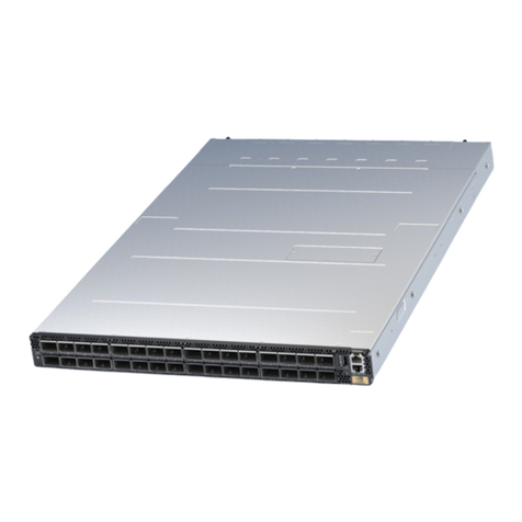
SN4600Front View
SN4600C Front View
SN4600/SN4600C Rear View
SN4700 Front View
SN4410/SN4700 Rear View
Speed and Switching Capabilities
The table below describes maximum throughput and interface speed per system model.

10
System
Model
Interfaces Supported Rates Max Throughput
SN4410 32 x QSFP-DD
8 x 400GbE
16 x 40/100/200GbE
32 x 1/10/25/50GbE
8Tb/s
SN4600 64 x QSFP56
64 x 40/200GbE
128 x 1/10/25/50/100GbE
25.6Tb/s
SN4600C
64 x QSF28 64 x 40/100GbE
128 x 1/10/25/50/100GbE
12.8Tb/s
SN4700 32 x QSFP-DD
32 x 400GbE
64 x 40/200GbE
128 x 1/10/25/50/100GbE
25.6Tb/s
*The system can support different interfaces and speed rates using QSFP/QSDP-DD to SFP adapters
or hybrid cables. For further information, see Splitter (Breakout) Cables and Adapters.
Management Interfaces, PSUs and Fans
The table below lists the various management interfaces, PSUs and fans per system model.
System Model uUSB MGT
(Management)
Console PSU Fan
SN4410 Front Front Front 2 units 6 units
SN4600 Front Front Front 2 units 3 units
SN4600C Front Front Front 2 units 3 units
SN4700 Front Front Front 2 units 6 units
Features
For a full feature list, please refer to the system’s product brief. Go to http://www.mellanox.com.
In the main menu, click on Products > Ethernet Switch Systems, and select the desired product
family.

12
Installation
System Installation and Initialization
Installation and initialization of the system require attention to the normal mechanical, power, and
thermal precautions for rack-mounted equipment.
The installation procedure for the system involves the following phases:
This document is preliminary and subject to change.
The rack mounting holes conform to the EIA-310 standard for 19-inch racks. Take
precautions to guarantee proper ventilation in order to maintain good airflow at ambient
temperature.
Due to thermal considerations, the switch systems must be installed in a horizontal
position. do not install the systems vertically.
Unless otherwise specified, NVIDIA products are designed to work in an environmentally
controlled data center with low levels of gaseous and dust (particulate) contamination.
The operation environment should meet severity level G1 as per ISA 71.04 for gaseous
contamination and ISO 14644-1 class 8 for cleanliness level.

13
• •
Step Procedure See
1 Follow the safety warnings
Safety Warnings
2 Pay attention to the air flow consideration within
the system and rack
Air Flow
3 Make sure that none of the package contents is
missing or damaged
Package Contents
4 Mount the system into a rack enclosure 19" System Mounting Options
5 Power on the system
Initial Power On
6 Perform system bring-up System Bring-Up
7 [Optional] FRU replacements FRU Replacements
Safety Warnings
Prior to the installation, please review the Safety Warnings. Note that some warnings may not apply
to all models.
Air Flow
NVIDIA systems are offered with two air flow patterns:
Power (rear) side inlet to connector side
outlet - marked with blue power supplies/fans
FRUs’ handles.
Connector (front) side inlet to power side
outlet - marked with red power supplies/fans
FRUs’ handles.
the images are provided for illustration purposes only. The design may slightly vary in
different systems
All servers and systems in the same rack should be planned with the same airflow direction.

14
•
•
•
•
•
•
•
•
•
•
•
•
The table below provides an air flow color legend and respective OPN designation.
Direction Description and OPN Designation
Connector side inlet to power side outlet. Red latches are placed on the
power inlet side.
OPN designation is “-R”.
Power side inlet to connector side outlet. Blue latches are placed on the
power inlet side.
OPN designation is “-F”.
Package Contents
Before installing your new system, unpack it and check against the parts list below that all the parts
have been sent. Check the parts for visible damage that may have occurred during shipping.
The SN4600/SN4600C package content is as follows:
1 xSystem
1 xRail kit
1 xPower cable for each power supply unit – Type C13-C14
1xHarness: HAR000028 – Harness RS232 2M cable – DB9 to RJ-45
1 xCable retainer for each power supply unit
The SN4410/SN4700 package content is as follows:
1 xSystem
1 xRail kit
4 xPower cables:
2 x 250V 10A 1830MM C14 TO C15 power cable
2 x 110V 15A 1830MM C14 TO C15 UL power cable
1 x Harness: HAR000631 – Harness RS232 2M cable – DB9 to RJ-45
2 x Cable retainers for each power supply unit
All FRU components need to have the same air flow direction. A mismatch in the air flow
will affect the heat dissipation.

15
•
•
•
•
•
•
Mounting Options
By default, the systems are sold with fixed rail-kits. Telescopic Rail-kits are available for some
systems, and should be purchased separately. For installation instructions, refer to the relevant links
in the following table:
System Model Fixed Rail-kit (Default) Telescopic Rail-kit
SN4600/SN4600C SN4600/SN4600C Fixed Rail Kit SN4600/SN4600C Telescopic Rail Kit
SN4410
SN4700
SN4410/SN4700 Fixed Rail Kit N/A
SN4600/SN4600C Fixed Rail Kit
Kit OPN Legacy OPN Rack Size and Rack Depth Range
930-9BRKT-00JF-000 MTEF-KIT-C 430-800 mm
The following parts are included in the fixed rail kit (see figure below):
2x Rack mount rails (A)
2x Rack mount blades (B)
2x Rack mount ears (C)
8x M6 Standard cage nuts (D)
8x M6 Standard pan-head Phillips screws (E)
4x Flat Head Phillips 100 DEG 6-32X1/4" ST.ST PATCH 360 (F)
Rack Rail Kit Parts
Ax2 Bx2 Cx2
If anything is damaged or missing, contact your sales representative atNetworking-
This document is preliminary and subject to change.

16
•
•
•
•
Dx8 Ex8 Fx4
Prerequisites:
Before mounting the system to the rack, select the way you wish to place the system. Pay attention
to the airflow within the rack cooling, connector and cabling options.
While planning how to place the system, consider the two installation options shown in the figures
below, and review the following points:
Make sure the system air flow is compatible with your installation selection. It is important to
keep the airflow within the rack in the same direction.
Note that the part of the system to which you choose to attach the rails (the front panel
direction, as demonstrated in Option 1 or the FRUs direction, as demonstrated in Option 2)
will determine the system’s adjustable side. The system’s part to which the brackets are
attached will be adjacent to the cabinet.
The FRU side is extractable. Mounting the rack brackets inverted to the FRU side (Option 2)
will allow you to slide the FRUs, in and out.
Short Racks (430-580 mm) Installation Options
Rear side (FRUs)
2. Front side (ports)
Standard Racks (580-800 mm) Installation Options

17
•Rear side (FRUs)
2. Front side (ports)
Short Racks (430-580 mm) Installation - Side View
Front side (ports):
Rear side (FRUs):
Standard Racks (580-800 mm) Installation - Side View
Front side (ports):
Rear side (FRUs):

18
1.
2.
3.
To mount the system into the rack:
Attach the left and right rack mount rails (A) to the switch, by gently pushing the switch
chassis’ pins through the slider key holes, until locking occurs.
Secure the chassis in the rails by screwing 2 flat head Phillips screws (F) in the designated
points with a torque of 1.5±0.2 Nm.
Attaching the Rails to the Chassis
Attach the left and right rack mount ears (C) to the switch, by gently pushing the switch
chassis’ pins through the slider key holes, until locking occurs. Secure the system in the
brackets by screwing the remaining 2 flat head Phillips screws (F) in the designated points
with a torque of 1.5±0.2 Nm.
Attaching the Brackets to the Chassis
The following steps include illustrations that show front side (ports) installation, yet all
instructions apply to all installation options.

19
4.
5.
Install 8 cage nuts (D) in the desired 1U slots of the rack: 4 cage nuts in the non-extractable
side and 4 cage nuts in the extractable side.
Installing the Cage Nuts
While your installation partner is supporting the system’s weight, perform the following
steps:
Attach the two rack mount blades (B) to the back side (FRU side) of the rack by inserting four
M6 screws (E) in the designated cage nuts. Do not tighten the screws yet.
Attaching the Brackets to the Rack
While each rack U (unit) consists of three holes, the cage nut should be installed
vertically with its ears engaging the top and bottom holes only.

20
6.
7.
Slide the switch with the rails (A) and ears (C) installed on it into the left and right rails (B)
on the rack. Use four M6 screws (E) to fix the rack mount ears (C) to the rack. Do not tighten
the screws yet.
Sliding the Blades in the Rails
When fully inserted, fix the switch by tightening the 8 screws (E) inserted in Step 5 and Step
6 with a torque of 4.5±0.5.
At least two people are required to safely mount the system in the rack.
This manual suits for next models
4
Table of contents
Other Nvidia Switch manuals

Nvidia
Nvidia P1453 User manual

Nvidia
Nvidia DU-07764-001 User manual

Nvidia
Nvidia Spectrum-2 SN3000 1U User manual

Nvidia
Nvidia QM9700 User manual

Nvidia
Nvidia Spectrum SN2000 Instructions for use

Nvidia
Nvidia TQ8 00 Series User manual

Nvidia
Nvidia QM87 Series User manual

Nvidia
Nvidia QM87 Series Installation instructions

Nvidia
Nvidia Spectrum-4 SN5000 2U Instructions for use

Nvidia
Nvidia Mellanox SB7700 Instructions for use