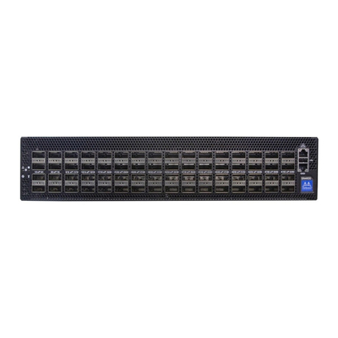
Nvidia Spectrum-4 SN5000 2U Instructions for use

Exported on Nov/02/2023 01:58 PM
NVIDIA Spectrum-4 SN5000 2U Switch
Systems Hardware User Manual
Rev. 1.0

2
Table of Contents
Ordering Information .......................................................................... 5
SN5400 Ordering Part Numbers ....................................................................5
SN5600 Ordering Part Numbers ....................................................................5
Introduction..................................................................................... 6
Speed and Switching Capabilities .................................................................7
Management Interfaces, PSUs and Fans ..........................................................7
Features ...............................................................................................8
Certifications .........................................................................................8
Installation...................................................................................... 9
System Installation and Initialization .............................................................9
Safety Warnings ......................................................................................9
Air Flow................................................................................................9
Package Contents .................................................................................. 10
Mounting Options .................................................................................. 11
SN5400/SN5600 Rail Kit ........................................................................... 11
Cable Installation .................................................................................. 19
Splitter (Breakout) Cables and Adapters ................................................... 20
Initial Power On .................................................................................... 22
System Bring-Up.................................................................................... 23
Configuring Network Attributes Using Cumulus Linux .................................... 23
Configuring Network Attributes Using SONiC .............................................. 23
FRU Replacements ................................................................................. 23
Power Supplies ................................................................................. 23
Fans .............................................................................................. 24
Interfaces ......................................................................................26
Data Interfaces ..................................................................................... 26
RS232 (Console) .................................................................................... 27
Management ........................................................................................ 27
USB ................................................................................................... 27
Reset Button ........................................................................................ 28
Status and Port LEDs............................................................................... 28
LED Notifications................................................................................... 28

3
System Status LED ............................................................................. 29
Fan Status LED.................................................................................. 29
Power Supply Status LEDs..................................................................... 30
Unit Identification LED........................................................................ 32
Port LEDs ........................................................................................ 32
Inventory Information ............................................................................. 34
Software Management .......................................................................36
Software Upgrade.................................................................................. 36
Cumulus Linux Software Upgrade ........................................................... 36
SONiC Software Upgrade...................................................................... 36
Switch Firmware Update...................................................................... 36
Troubleshooting ...............................................................................37
Specifications..................................................................................38
SN5400 Specifications ............................................................................. 38
SN5600 Specifications ............................................................................. 38
Appendixes.....................................................................................40
Accessory and Replacement Parts ............................................................... 40
Thermal Threshold Definitions................................................................... 40
Interface Specifications........................................................................... 41
Small Form Factors Specifications .......................................................... 41
USB Standard Specifications.................................................................. 41
RJ45 to DB9 Harness Pinout .................................................................. 41
Disassembly and Disposal ......................................................................... 41
Disassembly Procedure........................................................................ 41
Disposal.......................................................................................... 42
Document Revision History ..................................................................43

4
Relevant for Models: SN5400 and SN5600.
About this Manual
This manual describes the installation and basic use of NVIDIA Ethernet switches based on the
NVIDIA® Spectrum-4 ASIC.
Ordering Information
SeeOrdering Information.
Intended Audience
This manual is intended for IT managers and system administrators.
Related Documentation
Document Description
Cumulus Linux User Guide This document contains information regarding the
configuration and management of the Cumulus® Linux®
software. See https://docs.cumulusnetworks.com.
SONiC User Manual and Release Notes To access SONiC documentation, log in to the NVIDIA
Enterprise Support Portal →Downloads →Switches and
Gateways →Switch Software →SONiC →Documentation
Tab.
Open Network Install Environment (ONIE) Quick
Start Guide
See https://github.com/opencomputeproject/onie/wiki/
Quick-Start-Guide/.
Hands-on workshops Cumulus on-site/remote training:https://
academy.nvidia.com/en/cumulus-linux-boot-camp/
On-site/remote services For any tailor-made service, contact nbu-services-
Revision History
A list of the changes made to this document are provided in Document Revision History.

5
Ordering Information
The following table lists ordering information for the available systems.
Please pay attention to the airflow direction when ordering your system. For more details, seeAir
Flow.
SN5400 Ordering Part Numbers
NVIDIA
SKU
Product Description Lifecyc
le
Phase
920-9N4
2C-00RB
-7C0
NVIDIA Spectrum-4 based 400GbE 2U Open Ethernet switch with Cumulus Linux
Authentication, 64 QSFP56-DD ports and 1 2xSFP28 port, 2 power supplies (AC), x86 CPU,
Secure-boot, standard depth, C2P airflow, Tool-less Rail Kit
Enginee
ring
samples
SN5600 Ordering Part Numbers
NVIDIA SKU Product Description Lifecycle Phase
920-9N42F-00RI-5N0 NVIDIA Spectrum-4 based 800GbE 2U Open Ethernet
switch with ONIE, 64 OSFP ports and 1 SFP28 port, 2
power supplies (AC), x86 CPU, Secure-boot,
standard depth, C2P airflow, Tool-less Rail Kit
Engineering samples
920-9N42F-00RI-7C0 NVIDIA Spectrum-4 based 800GbE 2U Open Ethernet
switch with Cumulus Linux Authentication, 64 OSFP
ports and 1 SFP28 port, 2 power supplies (AC), x86
CPU, Secure-boot, standard depth, C2P airflow,
Tool-less Rail Kit
Engineering samples

6
•
•
Introduction
The NVIDIA Spectrum SN5000 series switches are the 5th generation of Spectrum switches, purpose-
built to accelerate data center fabrics. The SN5000 series provides port speeds spanning from 40GbE
to 800GbE, and delivers accelerated Ethernet to every data center. The SN5000 series is ideal for
enabling cloud-scale infrastructure for data centers of any size. The SN5000 switch systems provide
high performance and consistent low latency along with support for advanced software defined
networking features, making them the ideal choice for AI, cloud, data analytics, and simulation
applications.
Powered by NVIDIA Spectrum-4 ASICs, the SN5000 series features dynamic, flexible shared buffers
and predictable wire speed performance. The SN5000 is built to accelerate NVIDIA platforms,
including NVIDIA EGXTM, NVIDIA DGX PODTM , and NVIDIA OVXTM SuperPODs, and AI solution stacks
such as NVIDIA AI Enterprise and NVIDIA LaunchPad. As part of the Spectrum platform, the SN5000
systems are pre-tested and pre-validated with NVIDIA’s full portfolio of Ethernet networking
technology, including BlueField DPUs, ConnectX SmartNICs, and LinkX interconnects. This end-to-end
switch to host solution is critical to powering accelerated workloads, and delivers the high
performance and innovative feature set needed to supercharge cloud-native applications at scale.
SN5000 switch systems are based on the high-performance Spectrum-4 ASIC with a bidirectional
switching capacity of up to 51.2 Tbps. SN5000 platforms are available in a range of configurations,
each delivering high performance combined with feature-rich layer 2 and layer 3 forwarding, ideally
suited for both top-of-rack leaf and fixed configuration spines. SN5000 series provides full wire
speed, cut through-mode latency, on-chip fully-shared 128MB packet buffering, and flexible port use
in addition to advanced capabilities. Combining a wide range of innovations in the area of
programmability, telemetry, and tunneling with industry-leading performance, NVIDIA SN5000 series
is capable of addressing the complex networking requirements of today’s data centers.
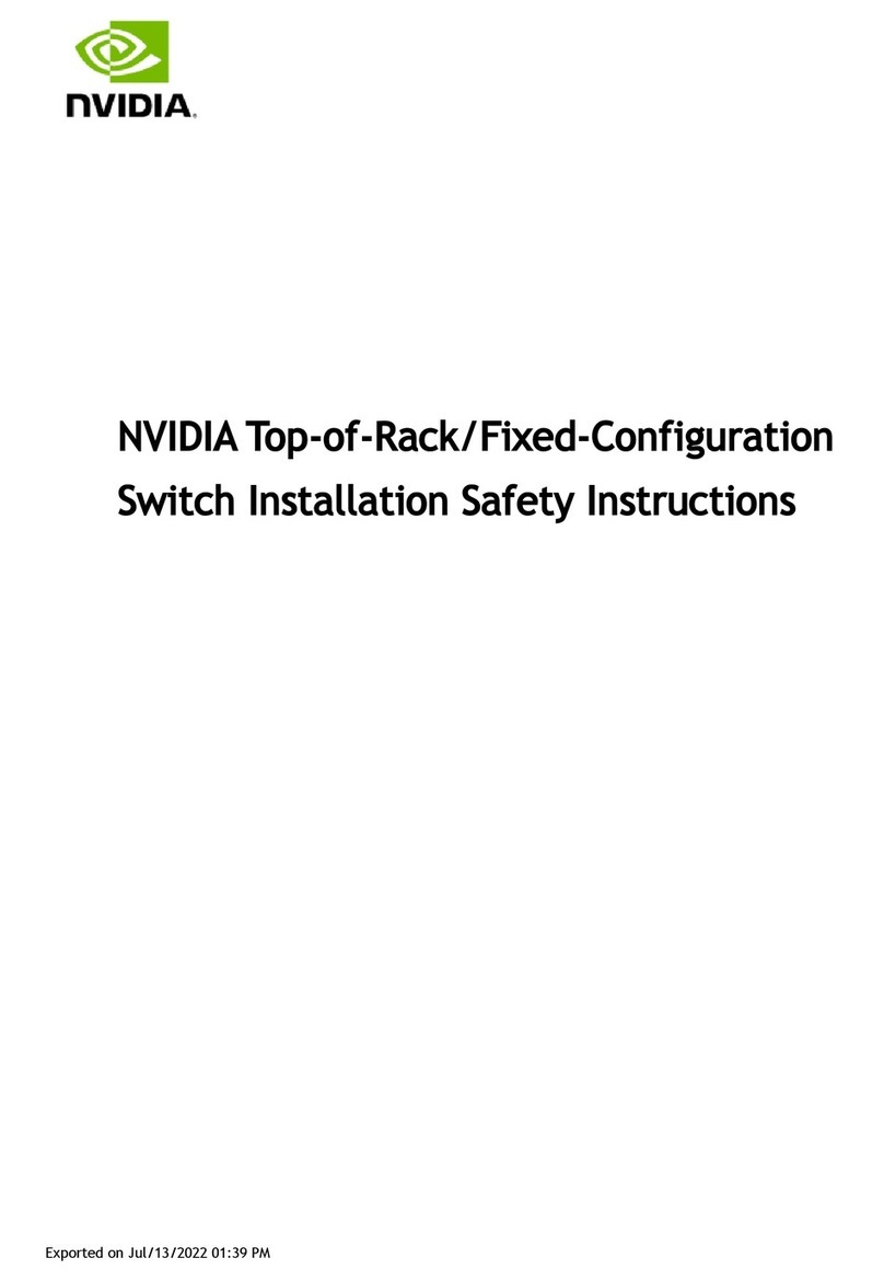
The SN5400 smart spine/super-spine offers 64 ports of 400GbE in a dense 2U form factor, fully
splittable to up to 128 ports of 200GbE or 256 ports of 10/25/50/100 GbE when used with
splitter cables.
The SN5600 smart spine/super-spine offers 64 ports of 800GbE in a dense 2U form factor, fully
splittable to up to 128 ports of 10/25/50/100/200/400GbE when used with splitter cables.
For a full list of all available ordering options, seeOrdering Information.
SN5400 Front View

7
SN5600 Front View
SN5400 and SN5600 Rear View
Speed and Switching Capabilities
The table below describes maximum throughput and interface speed per system model.
System
Model
Interfaces Supported Rates Max Throughput
SN5400 64 QSFP-DD 400GbE
2xSFP28 25GbE
64 x 400GbE
128 x 200GbE
256 x 10/25/50/100GbE
25.6Tb/s
SN5600 64 OSFP 800GbE
1xSFP28 25GbE
64 x 800GbE
128 x 400GbE
256 x 10/25/50/100/200GbE
51.2Tbps
*The systems support different interfaces and speed rates using QSFP/QSDP-DD to SFP adapters or
breakout cables. For further information, see Splitter (Breakout) Cables and Adapters.
Management Interfaces, PSUs and Fans
The table below lists the various management interfaces, PSUs and fans per system model.
System Model USB-A RJ45 MGT (Management) RJ45
Console
PSU Fan
SN5400 Front Front Front Yes, 2 Yes, 4
SN5600 Front Front Front Yes, 2 Yes, 4
1GbE is supported only in SFP28 ports
#65 and #66.
1GbE is supported only in SFP28 port
#65.

8
Features
For a full feature list, please refer to the system’s product brief. Go to https://www.nvidia.com/en-
us/networking/. In the main menu, click on Products > Ethernet Switch Systems, and select the
desired product family.
Certifications
For a list of certifications (such as EMC, Safety and others) per system for different regions of the
world, please contact your NVIDIA representative.

9
Installation
System Installation and Initialization
Installation and initialization of the system require attention to the mechanical, power, and thermal
precautions for rack-mounted equipment.
The installation procedure for the system involves the following phases:
Step Procedure See
1 Follow the safety warnings Safety Warnings
2 Pay attention to the air flow consideration within
the system and rack
Air Flow
3 Make sure that none of the package contents is
missing or damaged
Package Contents
4 Mount the system into a rack enclosure 19" System Mounting Options
5 Power on the system Initial Power On
6 Perform system bring-up System Bring-Up
7 [Optional] FRU replacements FRU Replacements
Safety Warnings
Prior to the installation, please review the Safety Warnings. Note that some warnings may not apply
to all models.
Air Flow
NVIDIA systems are offered with two air flow patterns:
The rack mounting holes conform to the EIA-310 standard for 19-inch racks. Take
precautions to guarantee proper ventilation in order to maintain good airflow at ambient
temperature.
Unless otherwise specified, NVIDIA products are designed to work in an environmentally
controlled data center with low levels of gaseous and dust (particulate) contamination.
The operation environment should meet severity level G1 as per ISA 71.04 for gaseous
contamination and ISO 14644-1 class 8 for cleanliness level.
The SN5400 and SN5600 systems are currently offered with one airflow type only -
Connector side inlet to power side outlet.

10
• •Power (rear) side inlet to connector side outlet
- marked with blue dots that are placed on the
power inlet side.
Connector (front) side inlet to power side
outlet - marked with red dots that are placed
on the power inlet side.
The table below provides an air flow color legend and respective OPN designation.
Direction Description and OPN Designation
Connector side inlet to power side outlet. Red dots are placed on the
power inlet side.
Power side inlet to connector side outlet. Blue dots are placed on the
power inlet side.
Package Contents
Before installing your new system, unpack it and check against the parts list below that all the parts
have been sent. Check the parts for visible damage that may have occurred during shipping.
the images are provided for illustration purposes only. The design may slightly vary in
different systems
All servers and systems in the same rack should be planned with the same airflow direction.
All FRU components need to have the same air flow direction. A mismatch in the air flow
will affect the heat dissipation.

11
•
•
•
•
•
•
•
The SN5400/SN5600 package content is as follows:
1 xSystem
1 xRail kit
2 x Power cables for each power supply unit – Type C20 to C19
1xHarness: HAR000028 – Harness RS232 2M cable – DB9 to RJ-45
2 x Cable retainers for each power supply unit
Mounting Options
By default, the systems are sold with fixed rail-kits. Telescopic Rail-kits are available for some
systems, and should be purchased separately. For installation instructions, refer to the relevant links
in the following table:
System Model Rail-kit
SN5400/SN5600 SN5400/SN5600 Rail Kit
SN5400/SN5600 Rail Kit
Kit Part Number Rack Size and Rack Depth Range
930-9SKIT-00L0-00A NVIDIA 600-800 mm Tool-Less Rail-Kit for 64x400G and 64x800G
Switch
The following parts are included in the tool-less rail kit (see figure below):
2x System Rails (A)
2x Rack Rails (B)
Rail Kit Parts
A B
OSFP air caps should be installed and maintained in ports which are not connected to
cables or modules.
If anything is damaged or missing, contact your sales representative atNetworking-
The illustrations show the SN5400 system, yet the installation procedures apply to SN5600
systems as well.
Prior to the installation procedure, inspect all rail-kit components and make sure none of
them is missing or damaged.If anything is missing or damaged, contact your NVIDIA
representative at[email protected].

12
•
•
•
Prerequisites:
Before mounting the system to the rack, select the way you wish to place the system. Pay attention
to the airflow within the rack cooling, connector and cabling options.
While planning how to place the system, review the two installation options shown in the table
below, and consider the following points:
Make sure the system air flow is compatible with your installation selection. It is important to
keep the airflow within the rack in the same direction.
Note that the part of the system to which you choose to attach the rails (the front panel
direction, as demonstrated in Option 1 or the FRUs direction, as demonstrated in Option 2)
will determine the system’s adjustable side. The system’s part to which the brackets are
attached will be adjacent to the cabinet.
The FRUs, as well as high-speed and MNG cables, must be extracted for replacement as part
of the switch service. Consider this when planning the switch installation.
Switch Rails Installation - Top View
Front Side (Ports) Rear Side (FRUs)

13
1.
2.
Attach the left and right system rails (A) to the switch.
Attaching the System Rails (A) to the Switch
Secure the assembly by gently pushing the system chassis’ pins through the slider key holes,
until locking occurs
The following steps include illustrations that show front side (ports) installation, yet all
instructions apply to all installation options.

14
3.
Securing the System in the Switch Rails (A)
Chassis' Pins in the Rails' Slots Locking them in a Fixed Position
Mount both of the rack rails (B) into the rack by angularly inserting the brakes located at the
rails edges into the designated slots in the rack unit, as shown in the following figure:

15
4.
Inserting the Rack Rails (B)
Align both rack rails (B) to sit horizontally in parallel to the rack assembly. By straightening
the rails' angular position, their breaks will be caught and locked in the rack's slots.
Aligning the Rack Rails (B) Angular Position The Breaks are Caught and Locked in the
Rack's Slots

16
5.
Rack Rails Fully Inserted and Locked in the Rack Assembly
Pull the rack rails' telescopic extensions all the way to the rack's opposite side, and insert the
latches at the rails' free edges to the rack's slots.A click should be heard as the spring latches
are fully inserted and locking occurs.
Ins
ert
ing
the
Spr
ing
Lat
ch
es
to
the
Ra
ck'
s
Slo
ts
To mount the system into the rack:
While your installation partner is supporting the system’s weight, perform the following
steps:
Two people are required to safely mount the system in the rack.

17
6.
7.
1.
2.
3.
Slide the rails installed on the system into the channels in the rack rails. Push them forward
until the locking mechanism is activated on both sides, and a click is heard.
Tighten the captive screws on both sides to further secure the system to the rack's posts.
Sliding the System's Rails (A) into the Rack Rails (B)
Sliding the System Rails (A) into the Rack Rails
(B)
Tightening the Captive Screws
To remove the system from the rack:
Turn off the system and disconnect it from peripherals and from the electrical outlet.
While your installation partner is supporting the system’s weight:
Loosen the captive screws attaching the system's rails to the rack's posts.
Use two hands to pull the system out until the rails are stopped.

18
4.
5.
Pulling the System Out
Press the spring latches on both sides of the rack, and continue to pull the system out until
the rack rails are clear of the system's rails.
Pressing the Spring Latches on Both Sides
Remove the rails from the system. Release the metal latches and pull out the rails, so the
system's pins will be removed out of the oval slots.

19
6.
Removing the Rails from the System
Remove the rails from the rack by pressing the lock button, and pull the rails outside of the
rack assembly.
Pressing the Lock Button to Remove the Rails from the Rack
Cable Installation
All cables can be inserted or removed with the unit powered on.

20
•
•
•
•
•
•
•
To insert a cable, press the connector into the port receptacle until the connector is firmly seated.
The LED indicator, corresponding to each data port, will light orange when the physical connection
is established. When a logical connection is made, the LED color will change to green.
To remove a cable, disengage the locks and slowly pull the connector away from the port
receptacle.The LED indicator for that port will turn off when the cable is unseated.
For a list of Supported Cables and Transceivers, please refer to theSN5000 Systems Datasheet.
For full cabling guidelines, ask your NVIDIA representative for a copy of NVIDIA Cable Management
Guidelines and FAQs Application Note.
For more information about port LEDs, refer to Port LEDs.
QSFP Cable Orientation
Splitter (Breakout) Cables and Adapters
When using an NVIDIA splitter cable, the following splitting options are available:
SN5400 (see"Splitting Options”):
When running at a 50GbE per lane, each 400GbE port can be split to 2 ports of 200GbE
or 4 ports of 100GbE without any limitation, or 8 ports of 50GbE while disabling
(unmapping) the 50GbE port above or below it.
When running at a 25GbE per lane, each 200GbE port can be split to 2 ports of 100GbE
or 4 ports of 50GbE without any limitation.
SN5600 (see "Splitting Options”):
When running at 100GbE per lane, each 800GbE port can be split to 4 ports of 200GbE
without any limitation, or 4 odd ports of 100GbE while disabling (unmapping) even
ports.
When running at a 50GbE per lane, each 400GbE port can be split to 2 ports of 200GbE
or 4 ports of 100GbE without any limitation.
When running at 25GbE, each 200GbE port can be split to 2 ports of 100GbE or 4 ports
of 50GbE without any limitation.
Do not push the cable connector into the receptacle using excessive force, as this may
cause damage to the cable or to the cage.
This manual suits for next models
5
Table of contents
Other Nvidia Switch manuals

Nvidia
Nvidia Spectrum SN2000 Instructions for use

Nvidia
Nvidia TQ8 00 Series User manual

Nvidia
Nvidia Spectrum-3 SN4000 Series Instructions for use

Nvidia
Nvidia Spectrum-2 SN3000 1U User manual

Nvidia
Nvidia P1453 User manual

Nvidia
Nvidia QM9700 User manual

Nvidia
Nvidia QM87 Series Installation instructions

Nvidia
Nvidia Mellanox SB7700 Instructions for use

Nvidia
Nvidia QM87 Series User manual

Nvidia
Nvidia DU-07764-001 User manual