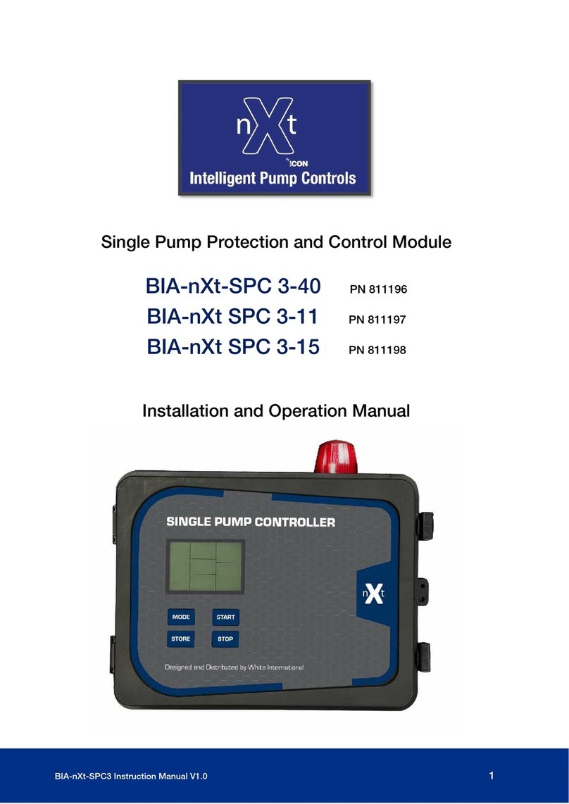
nxt BIA-nXt-Protect 1-22 User manual

BIA-nXt-PROTECT1 Instruction Manual 1
craiAuto Restart Pump Controller
Single Pump Protection and Control Module
BIA-nXt-Protect 1-22 PN 811202
Installation and Operation Manual

2BIA-nXt-PROTECT1 Instruction Manual
A. Shortcuts
Alarm Test:
In manual mode
PRESS and HOLD the
STORE/SET button
for 3 seconds
Error log:
•Switch to MANUAL mode
•Ensure no pumps are
running.
•PRESS and HOLD the
AUTO/MANUAL button, for
5 seconds
Accumulated
Run time:
Controller in manual
state.
Press and hold
STORE/SET and
START/STOP together
Switching
between AUTO
and MANUAL:
Hold the AUTO/MANUAL
button for 5 seconds.
Alarm Mute:
At any time press the
START/STOP button
to mute the alarm. It
will now beep every 5
minutes

BIA-nXt-PROTECT1 Instruction Manual 3
B. Shortcuts cont
Programming:
START/STOP increases a value
AUTO/MANUAL decreases a value
Press STORE/SET to proceed
through the parameter menu
Long press STORE/SET to store all
changes and exit
To clear the
calibration
With the pump stopped and
the controller in manual mode,
PRESS and HOLD the
START/STOP button for 30
seconds
Calibrating
the controller
to the pump
In manual mode, short press START/STOP.
Allow the pump to run and the current draw
to stabilise.
Once you are satisfied the pump is in its
‘normal’ operating range a short press of the
STORE/SET
button will cause the controller
to chirp indicating success.
The controller calibration values can be
entered Parameter #001 - 003 Pg 13
Programming
menu
In manual mode, with no
pump running, press the
STORE/SET button for 5
sec.
Auto calibration will
populate parameters
001 as 70%, 002 as
140%, 003 as 170%.
These may be
manually altered in the
programming menu

4BIA-nXt-PROTECT1 Instruction Manual
1. Introduction
Thank you for choosing a Bianco nXt-Protect single pump control and protection module.
The nXt-Protect is a module intended to control and protect an individual single phase
pump. The user can select a control logic sequence to match their application and enjoy the
benefits of superior control and protection for the pumps.
There are 3 primary control logic modes:
•‘Drainage’ where control is concentrated at the source
•‘Boosting’ which references pressure switching on the delivery side for control
•‘Transfer’ which is a mix of source and destination control
The LCD screen displays the pump running state and provides the user a wealth of useful
information.
The controller is easy to set up with an initial push button calibration and individual
parameters can be fine-tuned.
A nXt-Protect controller is particularly useful where there is the need to control and protect
pump installations managing the automatic operation through a variety of switching
methods without the need to create a bespoke control solution.
2. Warnings and Cautions
Read the manual carefully before starting
Prior to starting installation or maintenance the controller must be
disconnected from the power supply.
Any changes or modification to the wiring must be carried out by
competent, skilled and suitably qualified personnel only.
A qualified electrician should correctly size and install circuit breakers
to protect the power supply. The fitment of additional surge protection
is recommended as good practice.
Never open the cover while controller is connected to electrical supply.
Disconnect and allow the internal electronics to discharge before
opening the cover
This appliance is not intended for use by persons (including children)
with reduced physical, sensory or mental capabilities, or lack of
experience and knowledge, unless they have been given supervision or
instruction concerning use of the appliance by a person responsible for
their safety. Children should be supervised to ensure that they do not
play with the appliance.
Ensure the controller is a suitable size for the pump motor (see
Section 6, Page 7: Technical Data). Size according to full load
current amperage.(P1 power)

BIA-nXt-PROTECT1 Instruction Manual 5
3. Contents
A. Shortcuts .................................................................................................. 2
1. Introduction .............................................................................................. 4
2. Warnings and Cautions ............................................................................. 4
3. Contents ................................................................................................... 5
4. ISO 7010 Symbols used in this manual ..................................................... 5
5. Modes of Operation................................................................................... 6
6. Technical Specifications ........................................................................... 7
7. Display ...................................................................................................... 8
8. Electrical Connections............................................................................ 10
9. Parameter Calibration............................................................................. 11
10. Program Parameters ............................................................................... 12
11. Quick guide: Transfer – source/destination control................................ 14
12. Quick guide: Drainage Mode, float connected to pump .......................... 15
13. Quick guide: Drainage Mode, floats connected to control...................... 16
14. Quick guide: Pressure Boosting – switched input................................... 17
15. Quick guide: Sensorless Time control..................................................... 18
16. Fault Messages ....................................................................................... 19
17. Warranties – Terms and Conditions ........................................................ 20
4. ISO 7010 Symbols used in this manual
Warning - Electrical safety
Warning – Potential consequences of use outside of intended
application(s). Includes environmental condition warnings.
Mandatory warning
Warning to disconnect power
Read carefully

6BIA-nXt-PROTECT1 Instruction Manual
5. Modes of Operation
On the main PCB there is a 2 position ‘Dip
Switch’
To alter the control logic to suit an application,
the installer must select the appropriate switch
position.
After selecting the desired switch position, cycle
the controller power to apply the setting.
Binary
Switch position
Control logic - Applications
1
‘Drainage’ Mode where the level control input is managed by
a flexible float on the pump.
2
‘Pressure Boosting’ Mode. Main control via (N/C) pressure
switch. Supports run / no run level protection at the source
via floats or probes.
3
‘Drainage’ Mode where the control inputs (generally level
floats or probes) are located at the source.
4
Default
Mode
‘Transfer’ Mode. Main control via control inputs (floats or
probes) at destination or by a pressure switch on the delivery
line. Supports run / no run level protection at the source.
4
Sensorless time control
When first powered on the nXt-Protect will display
the current dipswitch operating mode (binary code),
the hardware and the software version.

BIA-nXt-PROTECT1 Instruction Manual 7
6. Technical Specifications
Controller Modes
Automatic or Manual pump operation.
Liquid level control via float switch or electrode probes.
Pressure control via pressure switch.
Protection functions: Dry run (Underload), Overload, Pump Stalled,
Open and reverse phase, Under voltage, Over voltage,
Short circuit, Pump Maximum run time
Input Voltage 230V +10% -6%
Rated output power Protect 1-22 nominal 0.37 to 2.2 kW P2 power (max 10A input)
Minimum Amperage 1.0 amp to achieve calibration successfully
Working temp -25 to +55 deg C
20% to 90% relative humidity, non-condensing
Controller size 200mm wide, 275mm tall,125 deep. IP54
Trip response times (set) Open phase – Less than 2 sec
Short circuit – less than 0.1 sec
Trip Voltage
(User adjustable)
Over voltage – Default = 265V
Under voltage – Default = 196V
Trip response times
(User adjustable)
Dry run (Under-load) 3 sec
Under Voltage Less than 5 sec
Over voltage Less than 5 sec
Recovery times
(User adjustable)
Dry run (Under-load) 30 min default
Overload 30 min default
Under Voltage 5 min default
Over voltage 5 min default
Alarms Audible alarm and flashing screen
To avoid ‘nuisance’ alarming, many of the default protection parameters
have values with a wide tolerance. The installer is encouraged to optimise
the settings to achieve optimum results

8BIA-nXt-PROTECT1 Instruction Manual
7. Display
The nXt-Protect display provides a real time indication of the operational mode and the
current state of the controller, including real-time voltage/current and any error messages.
Only the icons relevant to the selected operational mode will display.
Operational
state
Error
messages
Controller
status
Amperage,
Voltage and
other values.
Current monitoring
Audible alarm
Flashing screen
provides visual alarm
indication
Operating logic
selection
Low voltage
input
connections
Power output connections
Critical fault
messages
Mains power input
External Capacitor Cavity

BIA-nXt-PROTECT1 Instruction Manual 9
7. Display con’t
The nXt-Protect controller operates according to pre-programmed logic applied to each
‘mode’.
Changing the Dip Switches inside the controller then cycling the power will activate the
selected logic mode.
Examples of common applications are detailed later in this manual but with an
understanding of how the controller responds to various inputs in each of the modes the
controller can be used for application other than what is suggested.
The appearance of the front display changes according to each mode and provides a visual
indication to the state of the input signals.
Lack of source
water
High pressure
Low pressure
Source water
full
Destination low
Overflow
Destination full
Avoid installing the nXt-Protect where it could experience the following conditions:
i. Where there is significant vibration and/or mechanical shock.
ii. Where it could be exposed to corrosive liquids or gasses, or to flammable
materials, solvents etc.
iii. Extreme heat and cold. Operating range -25oC - 55oC.
iv. Protect the controller from rain, moisture, humidity or dust

10 BIA-nXt-PROTECT1 Instruction Manual
8. Electrical Connections
Always use an electrical outlet that is protected by Residual Current Device
(RCD) Safety Switch with a trip current of 30mA or less. A Safety switch is
required by Australian/New Zealand Standard AU/NZS 60335.1-2011.
All high voltage wiring must be connected by a suitably qualified technician.
The nXt-Protect 1-22 has an internal cavity to
hold an external start capacitor. This is
especially useful when protecting and
controlling ‘3 wire’ single phase bore pumps.
Note that nXt-Protect is intended to control a standalone single pump only.
If the installation must connect to a BMS or must operate an external alarm, enquire about
nXt SPC/DPC controllers
It is the responsibility of the installing electrical technician to ensure that the
cable cross section (mm2) meets the requirements of AS/NZS 3008; taking
into consideration the cable type, the cable length, the current draw and
other relevant factors.
If in doubt online resources exist i.e. Cable Size Calculator AS/NZS 3008 or seek advice
from an electrical engineer or other suitably qualified person(s)

BIA-nXt-PROTECT1 Instruction Manual 11
9. Parameter Calibration
The pump must be able to pump water to enable correct calibration.
Calibrated without water, overload and pump stalled errors may occur later.
Calibration can be performed automatically as detailed in the shortcuts on
page 3. Alternately the user can enter Underload, Overload and Pump Stalled
Amperages at Parameters 001, 002 and 003
Always perform a fresh calibration after installing a new pump, or when
reinstalling an existing pump following maintenance.
Either erase the existing calibration or manually program Parameters 1 -3.
Controller operation is managed using the
buttons on the front cover and a sequence of
short, long and combination button presses.
To access parameter settings the controller should be in its Manual operational mode and
the pump should NOT be running.
Press and hold STORE/SET for 5 sec to enter the parameter menu.
To enter a parameter, press the STORE/SET button. This will display the current value for
the parameter.
●Press the START/STOP button to increase a value.
●Press the AUTO/MANUAL button to decrease a value.
To store the value and return to the main menu press STORE/SET button.
To store all changes and exit the parameter menu press the STORE/SET button
Pump current draw MUST be greater than 1 amp for Auto Calibration to be successful.
Grinder / Macerating Pumps
Manually programming the nXt-Protect around the pump nameplate Full Load Current
allows the pump to generate maximum torque.
This may be a preferred alternative to calibration around the ‘normal’ hydraulic loading
current value in situations with heavily contaminated liquids.
Full factory reset_
•Turn off power to the control panel,
•Press and hold START/STOP as the power is turned on
•When the display shows 099, release the START/STOP button.

12 BIA-nXt-PROTECT1 Instruction Manual
10. Program Parameters
Press to switch between AUTO and MANUAL mode
The controller operating mode will be displayed in the top left corner of the
display
ITEM DEFAULT OPERATION
001 0.0 A Dry run protection trip amperage: Auto config to 70% of calibration value
002 26 A Over load protection trip amperage: Auto config to 140% of calibration
value
003 33.1 A Pump stalled trip amperage: Auto config 170% of calibration value
The user may manually tune parameters 001, 002 and 003 to alter the auto configuration values
004 352V Under voltage trip voltage
005 476V Over voltage trip voltage
006 6 sec Dry run protection trip response time: range 0 – 254 sec
007 30 min Dry run protection recovery time: range 0 – 254 min
008 00
Timer control (auto mode) – Parameters 009 – 101
00 = inactive
01 = active
009 5 min Pump run timer: range 0 – 254 min
010 5 min Pump Stop timer: range 0 – 254 min
011 0 min Pump stop time (manual mode): range 0 – 254 min
012 5 min LCD backlight timeout: range 0 – 254 min
013 00 min Maximum run time alarm in Boosting mode: range 1 – 254 min
014 00 Button Lock – set to 01 to activate
Manual/Auto and Store buttons to unlock
015 ON Open Phase Protection
When using the nXt SPC in conjunction with a VFD set to OFF
016 ~ Pump start delay time: range 0 – 254 sec
017 ~ Pump stop delay time: range 0 – 254 sec
AUTO
MANUAL

BIA-nXt-PROTECT1 Instruction Manual 13
nXt-Protect controllers are a cost
effective, reliable means to provide
better control and protection without
the need for costly bespoke
switchboards
The following quick guides provide
information regarding common
applications.
The pumps illustrated in the following
quick guides are mostly submersible
type but the nXt-Protect controller is
not limited to this type of pump.
With an understanding of how the
controller responds to various inputs in each of the modes the controller can be used for
applications beyond what is suggested.
For example, the controller can be connected in series with a VFD controlled pump to
provide additional control inputs or to utilise the nXt-Protect controller delay times.
For even greatly flexibility in your installation the nXt-Protect controller can be used as a
‘module’ in a more complex control environment.
Floats
3 wire’ floats allow for NO or NC wiring.
Connecting to the
controller using the
black and brown wires
the circuit is closed
when the float is up,
open circuit when the
float is down.
For greater differential,
dual floats can be
attached on the source
inputs 1, 2 and 3.
When using a single
float on the source
input terminals #2 and
#3 need to be bridged

14 BIA-nXt-PROTECT1 Instruction Manual
11. Quick guide: Transfer – source/destination control
Default mode - As Supplied
Pump On/Off operation is requested by a normally closed float or probes at the
destination or a pressure switch in the delivery line.
A normally closed float switch at the source controls whether the pump will run or not
depending on the liquid level.
Set the dip switches on
the main PCB and cycle
the power
In situations where the destination is a significant
distance from the source it is possible to control
by fitting a normally-open pressure switch to the
delivery line OR to use a remote wireless sensor
to trigger a switched input.
Connect across #4 and #5

BIA-nXt-PROTECT1 Instruction Manual 15
12. Quick guide: Drainage Mode, float connected to pump
The pump On/Off operation is controlled by the float fitted to the pump.
The Controller provides additional protections excluding dry run protection.
A float connected to the controller can provide high level alarm function
Parameter 001 must remain set to 0.0A to prevent underload alarming when the pump float
interrupts pumping operation
Set the dip switches on
the main PCB
and cycle
the power

16 BIA-nXt-PROTECT1 Instruction Manual
13. Quick guide: Drainage Mode, external control inputs
A pump with its own float can be used in this
configuration so long as the operational level of
Pump Stop Switch #1is HIGHER than the
float attached the pump.
Switched input - bridge terminals 5/6 and 2/3.
Pump switches on when the Pump Start switch 1/3 is in the On (Up) position
Pump runs until the Pump Stop switch 1/3 is in the Off (Down) position
High-Level alarm triggers when the High Level alarm switch 4/6 is in the On (Up) position.
The alarm will turn off when the Hi Level alarm switch 4/6 in in its Off (Down) position.
The pump will continue to run until the Pump Stop switch 1/3 is in the Off (down) position
See page 13 for wiring twin control floats to achieve greater switching differential
Set the dip switches on
the main PCB and cycle
the power

BIA-nXt-PROTECT1 Instruction Manual 17
14. Quick guide: Pressure Boosting
Pump On/Off operation is controlled via a pressure switch on the delivery line.
Additional (optional) run/no run protection can be fitted at the source
Or employ probes at the source
Set the dip switches on
the main PCB and cycle
the power

18 BIA-nXt-PROTECT1 Instruction Manual
15. Quick guide: Sensorless Time control
In Auto mode, any a ‘normal’ START REQUEST actives the timer(s) 009 / 010 until that start
request is terminated.
The next start request resets the timer count
008 00 Timer control (auto mode) – Parameters 009 – 101
00 = inactive
01 = active
009 5 min
Pump run timer: range 0 – 254 min
In Auto mode the pump will run for the time set then stop and
consider parameter 010 value
An input requesting the pump to start after stopping takes priority and
resets the timer count
010 5 min
Pump Stop timer:
range 0 – 254 min
In Auto mode having turned off at parameter 009 value the pump will
remain off for the parameter 010 value then restart running for
parameter 009 value etc
Application example: A low yielding bore controlled by a pressure switch.
•The pump starts on the pressure switch input but through experience, the customer knows it
can only run for 10 mins before it will run dry and then will need 20mins for the water to
recover.
•Set 009 to 10 minutes, and 010 to 20minutes.
•Activated by the pressure switch the pump will run for 10mins, turn off for 20mins then run
again for 10mins etc.
•If the destination tank fills closing the ballcock the pressure switch will turn the pump off
irrespective of the 009 run time.
•The process will start again on next run cycle
In Manual operation mode, the pump can be set running and it will switch off after the time
value at parameter 011 has passed.
011 0 min
Pump stop timer (manual mode):
range 0 – 254 min
In Manual operation mode the pump can be set running and it will
stop after the time set in parameter.
Set the dip switches on
the main PCB and cycle
the power

BIA-nXt-PROTECT1 Instruction Manual 19
16. Fault Messages
Fault Message Possible Cause Potential Solutions
UNDER V
The actual running voltage is lower
than the calibrated voltage parameter
004. The pump is in an under-voltage
protection state
The controller will attempt to restart
the pump every 5 minutes until line
voltage is restored to normal
If this fault occurs repeatedly, report
low line voltage to the power supply
company
OVER V
The actual running voltage is higher
than the calibrated voltage parameter
005. The pump is in over-voltage
protection state
The controller will attempt to restart
the pump every 5 minutes until line
voltage is restored to normal
If this fault occurs repeatedly, report
high line voltage to the power supply
company
PUMP STALLED
The pump motor running amperage
has exceeded the normal (calibrated)
running amperage by more than
parameter 003
This could be due to physical
jamming or a mechanical issue.
If the pump stalled error occurs
repeatedly at commissioning check
the controller rating is matched to the
pump
Pump Stalled is a ‘critical error’ and
will not automatically reset.
Isolate the power supply and inspect
the pump for anything which has
caused the sudden increase in load
OVER LOAD
Pump motor running amperage
exceeds the normal (calibrated)
running amperage by more than
parameter 002
Isolate the power supply and inspect
the pump for anything which is
causing the pump to draw more
amperage than the initial calibration
value
UNDER LOAD
Pump motor running amperage is less
than the normal (calibrated) running
amperage by more than parameter
001
Under-load is sometimes referred to
as Dry-run protection as a pump
motor will draw less current when
there is no load.
OPEN PHASE The power supply has lost power. Check fuses and wiring.
PUMP NO
CALIBRATION Calibration not complete Check the calibration.
Pump draw must exceed 1 amp

20 BIA-nXt-PROTECT1 Instruction Manual
17. Warranties – Terms and Conditions
This warranty is given in addition to the consumer guarantees found within the Australian
Competition and Consumer Act 2010 (Cth) for goods purchased in Australia and the
Consumer Guarantees Act 1993 NZ for goods purchased in New Zealand:
1) White International Pty Ltd / White International NZ Ltd (White International) warrant that all products
distributed are free from defects in workmanship and materials, for their provided warranty period as
indicated on the top or opposite side of this document. Subject to the conditions of the warranty, White
International will repair any defective products free of charge at the premises of our authorised service agents
throughout Australia and New Zealand if a defect in the product appears during the warranty period. If you
believe that you have purchased a defective product and wish to make a claim under this warranty, contact
us on our Sales Hotline on 1300 783 601, or send your claim to our postal address or fax line below and we
will advise you as to how next to proceed. You will be required to supply a copy of your proof of purchase to
make a claim under this warranty.
2) This warranty excludes transportation costs to and from White International or its appointed service agents
and excludes defects due to non-compliance with installation instructions, neglect or misuse, inadequate
protection against the elements, low voltage or use or operation for purposes other than those for which they
were designed. For further information regarding the suitability of your intended application contact us on
our Sales Hotline on 1300 783 601. If you make an invalid claim under this warranty, the original product will
be sent back to you unrepaired.
3) This warranty refers only to products sold after the 1st January 2012, and is not transferable to another
product type and only applies to the original owner, purchaser or end user, and is in addition to the consumer
guarantees found within the Competition and Consumer Act 2010 (Cth) for goods purchased in Australia and
the Consumer Guarantees Act 1993 (NZ) for goods purchased in New Zealand.
4) Our goods come with guarantees that cannot be excluded under the Australian Consumer Law. You are
entitled to a replacement or refund for a major failure and for compensation for any other reasonably
foreseeable loss or damage. You are also entitled to have the goods repaired or replaced if the goods fail to
be of acceptable quality and the failure does not amount to a major failure. 2 YEAR WARRANTY
5) To the fullest extent permitted by law, White International excludes its liability for all other conditions or
warranties which would or might otherwise be implied at law. To the fullest extent permitted by law, White
International’s liability under this warranty and any other conditions, guarantees or warranties at law that
cannot be excluded, including those in the Competition and Consumer Act 2010 (Cth), is expressly limited
to: (a) in the case of products, the replacement of the product or the supply of equivalent product, the
payment of the cost of replacing the product or of acquiring an equivalent product or the repair of the product
or payment of the cost of having the product repaired, is at the discretion of White International or a 3rd party
tribunal elected under the Competition and Consumer Act 2010 (Cth) for goods purchased in Australia and
the Consumer Guarantees Act 1993 (NZ) for goods purchased in New Zealand; and
6) To the fullest extent permitted by law, this warranty supersedes all other warranties attached to the product
or its packaging.
7) In the case of services, supplying the services again or the payment of the cost of having the services
supplied again, is at the discretion of White International or a 3rd party tribunal elected under the Competition
and Consumer Act 2010 (Cth) for goods purchased in Australia and the Consumer Guarantees Act 1993 (NZ)
for goods purchased in New Zealand. 8) Our warranty commences from the date of purchase of the above-
mentioned pumps. Proof of purchase is required before consideration under warranty is given.
Record your date of purchase in the space below and retain this copy for your records.
Date of Purchase ..................................................Model Purchased ..............................................
This manual suits for next models
1
Table of contents
Other nxt Control System manuals
Popular Control System manuals by other brands

Soundoff Signal
Soundoff Signal Blueprint 500 Series manual

SICE Tech
SICE Tech WHY PRO WHY-PH1 INSTRUCTION MANUAL AND WARNINGS

ICA
ICA FRc Series user manual

Ansul
Ansul AutoPulse Z-28 instructions

Parklio
Parklio Brain user manual

PLC Electronic Solutions
PLC Electronic Solutions HEDEN YMER 3 Operator's guide