NZR DHZ Series User manual

Stand: 09.01.2008
Last revised: 14.04.2008
Digital Active Energy, Dual-Tariff, Export & Import Meter
Installation and Operating Manual
NORDWESTDEUTSCHE ZÄHLERREVISION
ING. AUG. KNEMEYER GMBH & CO. KG
Heideweg 33
49196 Bad Laer
Phone +49 (0) 54 24 / 29 28 – 0
Fax +49 (0) 54 24 / 29 28 – 77
E-Mail [email protected]
Internet www.nzr.de

2
The information published in this manual is protected by copyright. Translations, reprints,
reproductions and storage in data processing systems are permitted only with the
express permission of NZR.
All trademarks and product names mentioned in this manual are the property of NZR
Nordwestdeutsche Zählerrevision Ing. Aug. Knemeyer GmbH & Co. KG or the respective
proprietors.
The content of this manual and the technical specifications can be supplemented,
modified or removed without prior notice.
The descriptions of the product specification in this manual do not constitute elements of
a contract.
© 2008 NZR Nordwestdeutsche Zählerrevision
Ing. Aug. Knemeyer GmbH & Co. KG.
All rights reserved.
If you have questions or suggestions, please contact us:
NZR Nordwestdeutsche Zählerrevision
Ing. Aug. Knemeyer GmbH & Co KG
Heideweg 33
D – 49196 Bad Laer
Tel.: +49(0) 52 24 / 29 28 - 0
Fax: +49(0) 52 24 / 29 28 - 77
Email: [email protected]
Internet: www.nzr.de

3
Contents
1 Preliminary remarks ................................................................................. 5
1.1 Safety information ...........................................................................................5
1.2 Maintenance...................................................................................................5
1.3 Information for the electric power customer.......................................................5
2 Mounting and installation ......................................................................... 6
2.1 Mounting ........................................................................................................6
2.2 Installation......................................................................................................7
2.2.1 Connection examples......................................................................................8
3 General description................................................................................ 10
4 Standards and regulations...................................................................... 11
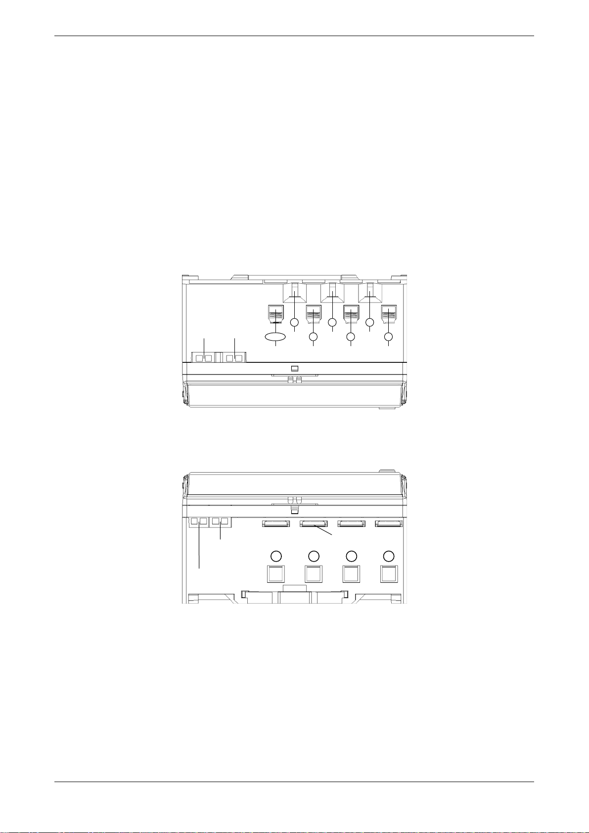
5Housing, control and display elements.................................................... 12
5.1 Overview......................................................................................................12
5.2 LC Display....................................................................................................13
6 Technical description ............................................................................. 14
6.1 Technical data .............................................................................................. 14
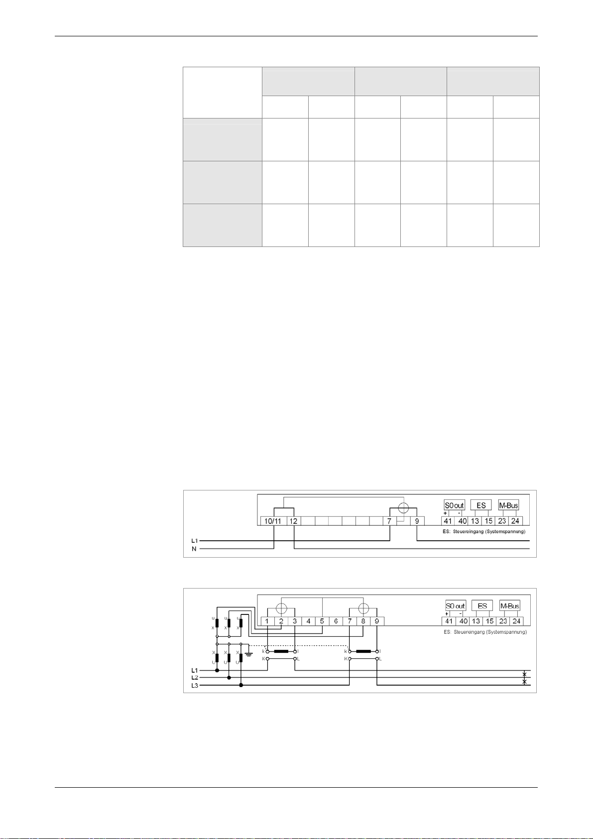
6.2 Operational diagram......................................................................................15
6.2.1 Direct-measuring meter up to 65 A................................................................. 15
6.2.2 Transformer connected meter up to 5 A..........................................................15
6.3 Inputs........................................................................................................... 16
6.4 Outputs ........................................................................................................16
6.4.1 Secondary impulse output .............................................................................16
6.4.2 Primary impulse output.................................................................................. 16
6.4.3 Test LED......................................................................................................17
6.5 Interfaces .....................................................................................................17
6.5.1 M-Bus interface ............................................................................................17
6.5.2 LON interface ...............................................................................................17
6.5.3 RS485 interface ............................................................................................18
6.6 Battery .........................................................................................................19
6.7 Path disconnector .........................................................................................19
7 Operation of the meter............................................................................ 20
7.1 Display control ..............................................................................................20
7.1.1 Standard menu .............................................................................................21
7.1.2 Test mode (only for calibration)......................................................................24
7.1.3 Address menu ..............................................................................................26
7.1.4 Edit menu.....................................................................................................28
8 Appendix................................................................................................ 32
8.1 EC Declaration of Conformity.........................................................................32
8.2 Declaration of Conformity for the EC Prototype Certificate ............................... 33

4
Illustrations
Figure 1: Housing dimensions .............................................................................6
Figure 2: Housing, control and display elements ................................................. 12
Figure 3: Layout of display ................................................................................13
Figure 4: Operational diagram of direct-measuring meter ....................................15
Figure 5: Operational diagram of transformer meter ............................................15
Figure 6: System layout – RS485 two-wire bus...................................................18
Figure 7: Detail drawing – RS485 terminating resistor ......................................... 18
Figure 8: DHZ with path disconnector ................................................................19
Tables
Table 1: Terminal dimensions, connection diameters, and torques .......................8
Table 2: Housing and display elements.............................................................12
Table 3: Description of display elements ...........................................................13
Table 4: Technical data....................................................................................14
Table 5: Specifications of inputs .......................................................................16
Table 6: Specifications of outputs .....................................................................16
Table 7: Specification of RS485 interface.......................................................... 18
Table 8: Error code description.........................................................................20
Table 9: Standard menu .................................................................................. 23
Table 10: Test mode ......................................................................................... 26
Table 11: Address menu....................................................................................27
Table 12: Resolutions of the energy registers...................................................... 28
Abbreviations
A active energy
+A positive active energy (customer purchases from utility co.)
-A negative active energy (customer delivers to utility co.)
Cl. accuracy class
DIN German Institute for Standardization
EN European standard
UC electric utility company
IEC International Electrotechnical Commission
Imp. impulse
Imp./kWh impulses per kWh
L1, L2, L3 lead wires
LED light emitting diode
N neutral wire
P active power
PTB Federal Institute of Physics and Technology
S0 interface according to DIN 43 864

5
1 Preliminary remarks
This manual describes all model variants and functions of the DHZ, firmware version
3.03 and above. Please note that the meters can be designed differently with respect to
configuration data interfaces, input/outputs, etc. Therefore, it is possible that meter
features are described that do not apply to the particular meter you are using.
1.1 Safety information
The meters are designed only for measuring electrical power and may not be operated
beyond the scope of the specified technical data
(see rating plate).
During installation or replacement of the meter, the wires to which the meter is
connected must be voltage-free. Use only the screw terminals provided. Contact with
voltage-carrying parts can result in fatal injury! Therefore, the corresponding inputs fuses
should be removed and stored so that other persons cannot use them inadvertently.
Before opening the unit, the secondary circuits of the current transformers (on the test
terminals) absolutely must be short-circuited. The high voltage at the interrupted current
transformer can cause fatal injury and will destroy the current transformer.
S0 inputs can carry mains voltage if the meter is installed incorrectly.
Caution: Danger to life and limb!
Always comply with local safety regulations. The meters may be installed only by
qualified and trained personnel.
1.2 Maintenance
The meter is maintenance-free. If it is damaged (e.g. during transport or storage) it
cannot be repaired by the user.
Opening the meter voids the warranty. The same applies in the event of defects resulting
from external influences (e.g. lightning, water, fire, extreme temperatures and weather
conditions, improper or negligent use or handling).
1.3 Information for the electric power customer
Information according to the Federal Institute of Physics and Technology:
The user must ensure that the mechanical equivalents for which the electric power
customer is charged are made transparent for the customers for whom the meters are
used. To "make transparent" means to provide information to the customers by means of
calibrated displays for the meters in order to allow the customer to understand the items
in the electric utility bill.
In particular, the following information must be provided:
- which of the values displayed by the meters are the results of calibrated functions,

- that values not displayed cannot be used for billing purposes and that display values
that are the results of non-calibrated functions, are provided only for information
purposes and likewise cannot be used for billing purposes.
The measuring instruments must be used so that the billing-relevant measuring results
and the error messages can be read by the electric power customer, as well.
2 Mounting and installation
2.1 Mounting
The meters of the DHZ series are designed for mounting on top-hat rails TH 35-7.5 in
accordance with DIN 60715.
Figure 1: Housing dimensions
6

2.2 Installation
The meter must be connected according to the wiring diagram, which you will find in the
terminal cover of the meter. Examples of wiring diagrams can be found on page 8.
The directly connected model of the DHZ can be connected on the output side to a 3- or
4-phase busbar with left-side N connection. The busbars are suitable for equipment from
AEG, Hager, Siemens, Moeller and Geyer.
Meters for direct connection must be protected by a 63 A input fuse; meters connected to
transformers in the voltage path with < 10 A. The control input must be protected with a
0.5 A input fuse.
To protect the DHZ from unauthorized access, it can be sealed with a lead seal (see
page 12).
The inputs for the current and voltage lines and for the control input and the impulse
output are located on the top of the meter.
S0 output input
8
U3
2
U1
5
U2
1
I1
4
I2
7
I3
10/11
N
41/40 13/15
The current outputs, the optional electrical interface and, for direct measuring meters, the
connection for busbars are located on the bottom of the meter.
M-Bus interface Connection for busbars
12
N
3
I1
6
I2
9
I3
23/24
LON/RS485 interface
14/16
7

Current terminal /
N terminal Voltage terminals Auxiliary
terminals
up to 65 A up to 5 A up to 65 A up to 5 A up to 65 A up to 5 A
Terminal
dimensions
W x H (d) mm 6.9 x 7.9 3.3 x 3.0 2.7 x 3.0 2.7 x 3.0 d = 2.5 d = 2.5
Maximum
connection
diameters (mm2)16 42.5 2.5 2.5 2.5
Maximum torques
for connection
terminals (Nm) 3.0 0.5 0.5 0.5 0.8 0.8
Table 1: Terminal dimensions, connection diameters, and torques
Note
During installation of the meter, tighten the connecting wires to the correct torque
according to EN 60999 to ensure a reliable contact. The torque depends on the type of
connecting wire and the maximum current.
To prevent damage to the meter, do not exceed the maximum permissible torque
for the connecting terminal.
2.2.1 Connection examples
Below you will find several examples of wiring diagrams. When connecting a meter,
always comply with the corresponding wiring diagram, which you will find in the terminal
cover of the meter.
Important: The neutral wire terminals 10/11 and 12 are located on the left.
2-wire model, connected directly
3-wire model, connected to current and voltage transformer
8

4-wire model, connected to current transformer
4-wire model, connected directly
4-wire model, connected to current and voltage transformer
4-wire model, connected to current and voltage transformer (3 voltage transformers –
superposed circuit with 2 current transformers)
4-wire model, connected to current and voltage transformer (superposed circuit with 2
current transformers)
9

10
3 General description
The DHZ is a digital single or dual-tariff meter for measuring positive and negative active
energy in 2-, 3- and 4-wire networks. The tariff switching is controlled via an external
control input.
The applications for the DHZ are primarily the recording of energy data in industrial and
building technology, switchgear construction and use in the energy supply sector.
The design of the meter enables space-saving installation (only 6 TE wide) and
connection via cable links or busbars.
The wall model of the DHZ features a configurable transformer ratio for recording the
actual energy consumption. The transformer ratio can be set directly on the meter via the
control button (only on the non-calibrated model).
The energy consumption values are displayed as an 8-digit number on an LCD.
The energy consumption data can also be output via a secondary or primary impulse
output and/or via an electric interface (M-Bus, LON or RS485). The impulse constant and
impulse length are configurable for the secondary impulse output; they have fixed values
for the primary impulse output.
The DHZ is available in accuracy class 1 or 2 according to IEC 62053-21 or accuracy
class B or A according to DIN EN 50470-1, -3.

11
4 Standards and regulations
DIN EN 14908-1, -2, Data Communication for Building Automation and
-3, -4 Building Management (LON)
DIN EN 13757-2, -3 Communication Systems for Meters and their Remote Reading
(M-BUS), Compatible Extension of EN 1434-3:1997
DIN EN 50470-1 AC Electricity Meters – Part 1: General Requirements, Tests
and Test Conditions - Measuring Devices (Accuracy Classes
A, B and C)
DIN EN 50470-3 AC Electricity Meters – Part 3: Special Requirements –
Electronic Active Energy Meters, Accuracy Classes A, B and C
DIN EN 60529 Protection Classes Through Housings (IP code)
DIN EN 60715 Dimensions of Low-Voltage Switchgear -
Standardized Mounting Rails for the Mechanical Mounting of
Electric Devices in Switchgear
DIN EN 61000-3-2, Electromagnetic Compatibility (EMC)
-4-2, -4-3, -4-4, -4-5,
-4-6, -4-11, -6-2
IEC 60068-2-30 Environmental Influences – Part2-30: Test Methods – Test Db:
Humid Heat, Cyclical (12 + 12 Hours)
IEC 62052-11 AC Electricity Meters – General Requirements, Tests and Test
Conditions – part 11: Measuring Devices
IEC 62053-21 AC Electricity Meters – Special Requirements - Part 21:
Electronic Active Energy Meters of Accuracy Classes 1 and 2
ITU-T V.11 Electrical Properties of Symmetrical Double Current
Interfaces for Data Rates up to 10 Mbit/s
TIA/EIA-485 Electrical Properties of Transmitters and Receivers in
Digital Measuring Systems

5 Housing, control and display elements
5.1 Overview
1 2 8475 63 9 10 11 12
12
13 14 15 16 17 18 19 20
Figure 2: Housing, control and display elements
No. Designation
1Hinged terminal cover
2LC Display
3Lead seal hole
4Neuron ID number (only on meters with LON interface)
5Protection class II
6Power network and load classification
7See enclosed pack
8Backstop or two-direction meter ( )
9EC prototype certificate (consisting of:
1st line: Test certificate number
2nd line: Temperature key, CE label, metrology sign +
Year of conformity assessment, name of the approval body)
or national approval symbol (e.g.. PTB: )
10 Slot for measuring transformer plate
11 Year
12 Push button for operating the meter
13 Hinged terminal cover
14 Serial number
15 Barcode
16 Test LED
17 Model designation / key
18 Impulse constant of the LED and of the output
19 Voltage, current, frequency and accuracy class
20 Circuit number
xx.xx
xx.xx
Table 2: Housing and display elements

5.2 LC Display
The meter display is a liquid crystal display (LCD) with the following layout:
Figure 3: Layout of display
1 2 3
5 6 7 8 9 10
4
No. Description
1Phase display
L1, L2, L3 illuminated: Phase voltages are present
L1, L2, L3 blinking: Phase sequence of voltage is incorrect
2Display of the active tariff
T1: Tariff 1 is active
T2: Tariff 2 is active
3Energy direction display
+P illuminated: Meter is started and registered
positive active energy.
-P illuminated: Meter is started and registered
negative active energy.
-P blinking: Backstop is active, energy is
not registered.
4Hand symbol
Blinking: Edit mode is active or was ended with
„Escape“. It is still possible to change the
data (not for calibration).
Illuminated: Edit mode was stopped with "Close“ and
can only be activated on meters that are
configured accordingly with a user password
(not for calibration).
Off: Edit mode was stopped with "Close“ and
cannot be activated again (for calibration).
5Tariff display
Tariff designation of the displayed energy value
6Energy direction of the register
In: Register for measuring pos. active energy
Out: Register for measuring neg. active energy
7Value range
Display of register content
8Star symbol
Blinking: Test mode active. Activated from the
standard menu.
9Display of the units
Unit of the value displayed in the value range
10 Communication symbol
Illuminates during communication via the electric interface
Table 3: Description of display elements
13

14
6 Technical description
6.1 Technical data
Transformer meter
5ll1 A / 5 + 1 A and 1 A Direct measuring meter
5(65) A / 0.25 – 5(65) A
4-wire meter 3x230/400 V, 3x290/500 V,
3x58/100 V, 3x63/110 V 3x230/400 V, 3x290/500 V
3-wire meter 3x100 V, 3x110 V,
3x400 V, 3x500 V 3x400 V, 3x500 V
Voltage
2-wire meter 1x100 V, 1x110 V, 1x230 V 1x230 V
Starting current 2 mA 20 mA
Frequency 50 Hz, 60 Hz, 162/3Hz
Class accuracy Active energy Class 1 or 2 according to IEC 62053-21
Class B or A according to DIN EN 50470-1, -3
Measuring types Active energy +A (with backstop), Option: -A
LED 1 000...400 000 Imp./kWh
(depending on type) 1 000…2 000 Imp./kWh
(depending on type)
Primary output 1 Imp./kWh (fixed)
Secondary output 100…200 000 Imp./kWh
(depending on type) 10…2 000 Imp./kWh
(depending on type)
Impulse values
Configurability Output impulse value in calibrated model or with declaration of
conformity according to MID has fixed parameters,
can be configured via button on non-calibrated model
Energy registers Quantity max. 2 tariff registers (T1 / T2) per energy direction
Quantity max. 1Control inputs for tariff
switching (option) System voltage 58...230 V AC
Data maintenance voltage-free in FLASH / EEPROM, at least 20 years
LC Display 8 digits,
with 3 decimal places 8 digitsDisplay
Size of digits 4 x 6 mm
Operation Mechanical button to start display
M-Bus according to DIN EN 13757-2, -3 (300…9600 Baud)
LON according to DIN EN 14908-1, -2, -3, -4
Data interfaces
(option)
RS485 according to TIA/EIA-485 and ITU-T V.11 (300…9600 Baud)
Quantity max. 1
Opto-MOSFET max. 250 V AC/DC, 100 mA for impulse forwarding
(complies with S0 specification)
Output (option)
S0 output max. 27 V DC, 27 mA (passive)
Power supply Switched mode power supply 3-phase from measuring voltage
Voltage path < 2.0 VA / < 1.0 WAuxiliary power per phase
Current path < 0.5 VA < 2.5 VA
Insulation strength Insulation: 4 kV AC, 50 Hz, 1 min
Surge voltage EMC: 4 kV, impulse 1.2/50 μs, 2 Ω
ISO: 6 kV, impulse 1.2/50 μs, 500 Ω
EMC properties
Resistance to HF fields 10 V/m (under load)
Temperature range Operation / marginal operation
and storage -25°C...+55°C / -40°C...+70°C
Relative humidity 95%, non-condensing according to IEC 62052-11,
DIN EN 50470-1, IEC 60068-2-30
Dimensions 6 TE = 107.5 x 89.5 x 64.2 mm (W x H x D)
Protection class 2
Protection type housing,
connections IP 20
Housing material polycarbonate
Fire properties highly non-flammable (halogen-free)
Housing
Weight ca. 400 g
Current / neutral wire max. 4 mm² max. 16 mm²Wire diameters
Voltage / additional terminals max. 2.5 mm² max. 2.5 mm²
Battery for reading in voltage-free state (option)
Instantaneous values for output, voltage and current
Additional features
Connection to a 3- or 4-phase
busbar with left-side N
connection, suitable for
equipment from AEG, Siemens,
Moeller, Hager and Geyer.
Table 4: Technical data

6.2 Operational diagram
6.2.1 Direct-measuring meter up to 65 A
Figure 4: Operational diagram of direct-measuring meter
6.2.2 Transformer connected meter up to 5 A
Figure 5: Operational diagram of transformer meter
15

16
6.3 Inputs
The dual-tariff model of the DHZ is equipped with one control input (system voltage) for
switching tariffs.
Specifications
System voltage 58...230 V AC (Standard)
Table 5: Specifications of inputs
6.4 Outputs
The DHZ is equipped with a potential-free S0 impulse output (according to DIN 43 864)
or potential-free MOSFET impulse output (solid-state relay). The MOSFET outputs can
be designed as openers or closers.
Specifications
Opto-MOSFET max. 250V AC/DC, 100 mA (Standard)
S0 max. 27 V DC, 27 mA (passive)
Table 6: Specifications of outputs
6.4.1 Secondary impulse output
Any configured transformer factors have no affect on the impulse output.
The impulse duration is 30, 50 or 100 ms depending on the model.
The energy impulses (RA) are 10, 100, 200, 500, 1 000, 2 000, 5 000, 10 000, 20 000,
50 000, 100 000 or 200 000 Imp./kWh depending on the model and are always
secondary.
6.4.2 Primary impulse output
Configured transformer factors affect the impulse output.
The impulse duration is 500 ms and the impulse value is set at 1 Imp./kWh.
Note:
For a meter with a configured primary impulse output, the function of the impulse output
not only depends on the instantaneous power, but also on the configured overall
transformer factors. The transformer factors must be set by the user to ensure a
sufficient impulse pause at maximum load. The impulse duration is set to 500 ms and
cannot be changed.
Example:
Meter connection type: 4-wire
UNom = 3x230/400 V
IMax = 5 A
Output impulse value: 1 Imp./kWh with 500 ms impulse duration
Total transformer factors = U factor x I factor = e.g. 1000
PMax = UNom x 15% x IMax
PMax = 3x230 V x 1.15 x 5 A = 3.968 kWh
Impulse frequency = impulse value x transformer factor / 3600 s
Impulse frequency = 3.968 kWh x 1 Imp./kWh x 1000 / 3600 s
Impulse frequency = 1.102 Hz => one impulse very 907 ms
With a fixed impulse duration of 500 ms the impulse pause is 407 ms
(907 ms – 500 ms).

17
6.4.3 Test LED
Any configured transformer factors have no affect on the test LED.
The LED constant (RL) depends on the model and is always secondary.
6.5 Interfaces
6.5.1 M-Bus interface
The M-Bus interface is designed according to DIN EN 13757-2, -3. The following
parameters can be transmitted via the M-Bus:
-Manufacturer ID, optional/freely selectable
-Medium
-Primary and secondary address of M-Bus
-Energy values
-Instantaneous value PSum
-Error status
Additional functions and details are described in the M-Bus description for the DHZ.
This data is output as a standard response and can be displayed by conventional tools
such as NZR-VADEV. Other parameters, such as the meter configuration or the editing
data, can only be read via manufacturer-specific M-Bus telegrams, such as those
supported by the NZR M-Tool.
6.5.2 LON interface
The LON interface is designed according to DIN EN 14908-1, -2, -3, -4 and is based on
the "LONMARK" specification, so that all LON modules can be combined in any
environment. Each LON module has a worldwide unique address (Neuron ID). This
address is defined at the time of manufacture and is printed on the rating plate of the
meter. The DHZ-LON-Bus supports free network topologies.
The following data can be retrieved via the LON interface:
-Energy values
-Instantaneous values: PSum, single phases of P, U and I
-Error status
-U and I transformer factors (changes are possible only in non-calibrated units with
active edit mode).
Additional functions and details are described in the LON description for the DHZ.
The LON interface, which is galvanically separated from the meter, is located on the
additional terminals 14 and 16.

6.5.3 RS485 interface
The electric interface RS485 is a symmetrical two-wire interface (half duplex) and is
designed according to TIA/EIA-485 / ITU-T V.11. The data protocol is the M-Bus
protocol. The following parameters can be transmitted via the RS485 interface:
-Manufacturer ID, optional/freely selectable
-Medium
-Primary and secondary address of M-Bus
-Energy values
-Instantaneous value PSum
-Error status
The RS485 interface, which is galvanically separated from the meter, is located on the
additional terminals 14 (A) and 16 (B).
Properties
Number of connected meters up to 32
Max. cable length up to 1,000 m
Data transfer rate 300 ... 9600 Baud
Signal according to TIA/EIA-485 / ITU-T
V.11 logical “1”
-0.3 V to -6 V logical “0”
+0.3 V to +6 V
Table 7: Specification of RS485 interface
RS485 standard bus
Up to 32 meters can be operated on one RS485 bus. Normally the first and last meters
in the bus system are terminated with a terminating resistor between wire "A" and "B" to
eliminate reflections.
Bus layout:
Unit 1 Unit 2 Unit 32
see detail
BA BA
. . .
RS485 two-wire bus
see detail
BA max. 5 m
max. 1000 m
Figure 6: System layout – RS485 two-wire bus
Detail: Important:
RS485
14 16
A
B
RTERM= 120
Ω
Connecting
terminals
The terminating resistor can be mounted
only on the first and last meter in the
bus.
Figure 7: Detail drawing – RS485 terminating resistor
18

6.6 Battery
The DHZ can optionally be equipped with an internal battery, which makes it possible to
read the meter in voltage-free state. If the meter is operated continuously by battery, the
life of the battery is at least 30 hours; in case of voltage-free reading once every month
(approximately 5 minutes), the battery will last about 30 years.
In battery operation the display automatically shuts off 20 seconds after the last time the
push button is pushed.
Note:
The battery used in the DHZ is a lithium battery with very low self-discharge. When
lithium batteries are stored or not used for an extended period, a protective film forms
over the inner contacts to prevent self-discharge. When the battery is used again, this
protective film has to be eliminated, so that the full voltage is available. Therefore, it may
be necessary to hold down the push button for up to 30 seconds before the unit is
operable.
6.7 Path disconnector
In the direct-measuring DHZ, it is possible to disconnect the voltage path from the
current path for inspection purposes. A special path separator, which is available as an
accessory, is used in this case.
Path disconnector
Figure 8: DHZ with path disconnector
19

20
7 Operation of the meter
The DHZ is operated via a mechanical button (push button), which is used to control the
display and make settings in the editing menu. If the meter is equipped with a battery,
the standard menu in the display can be opened when the unit is voltage-free.
The test mode, the address menu (on meters with an electric interface) and the editing
menu are then not available, however.
7.1 Display control
Observe the following for operation of the meter via the push button:
-"short" actuation (tactuation < 2 s) switches to the next list value or menu item (switching
takes place when the button is released)
-"long" actuation (2 s ≤tactuation < 5 s) activates the currently displayed menu item
(switches after 2 seconds, not when button is released)
-"extended" actuation (tactuation > 5 s) returns to the standard display from every state
in the display mode (activates the selected menu item after 2 seconds; jumps to the
standard directory after 5 seconds)
During normal operation of the meter the standard menu is active. If the display is in any
other state, the display automatically returns to the standard display of the standard
menu 5 minutes after the last time the button is pushed.
On meters with a LON interface, the Neuron ID number on the bus is automatically sent
to the LON software when the button is pushed. This facilitates integration of meters in
the bus.
To ensure trouble-fee operation of the meter, the following are constantly checked during
operation:
-checksum via the program code
-checksum via the parameterization data
-checksum via the editing data
If an error occurs during these checks, this is displayed as an error code:
Error code Explanation
00000001 Program code faulty
00000002 Parameterization data faulty
00000003 Editing data faulty
Table 8: Error code description
If an error is displayed, operation may be impaired. The error code can only be reset at
the factory.
This manual suits for next models
2
Table of contents
Other NZR Measuring Instrument manuals
Popular Measuring Instrument manuals by other brands

Hanna Instruments
Hanna Instruments HI 96770 instruction manual

Extech Instruments
Extech Instruments SP505 user manual

AEMC instruments
AEMC instruments Measure Up PowerPad III quick start guide

GTC
GTC CM100 manual

Bacharach
Bacharach Monoxor Plus Configuration and operation manual

SAPHYMO
SAPHYMO MiniTRACE CSDF manual

Pivot
Pivot CHRONOSTEP user manual

Witschi
Witschi ChronoMaster manual

Hach
Hach 1735 TRO Hazardous Location Installation Manual

SubSurface Instrument
SubSurface Instrument AML PRO Series Operator's manual

Precision Digital Corporation
Precision Digital Corporation ProtEX-RTP PD6830 Series instruction manual

sewerin
sewerin FLIS-EX operating instructions