O&M D3250 User manual

Maximum span - 7.0
100 % Duty cycle
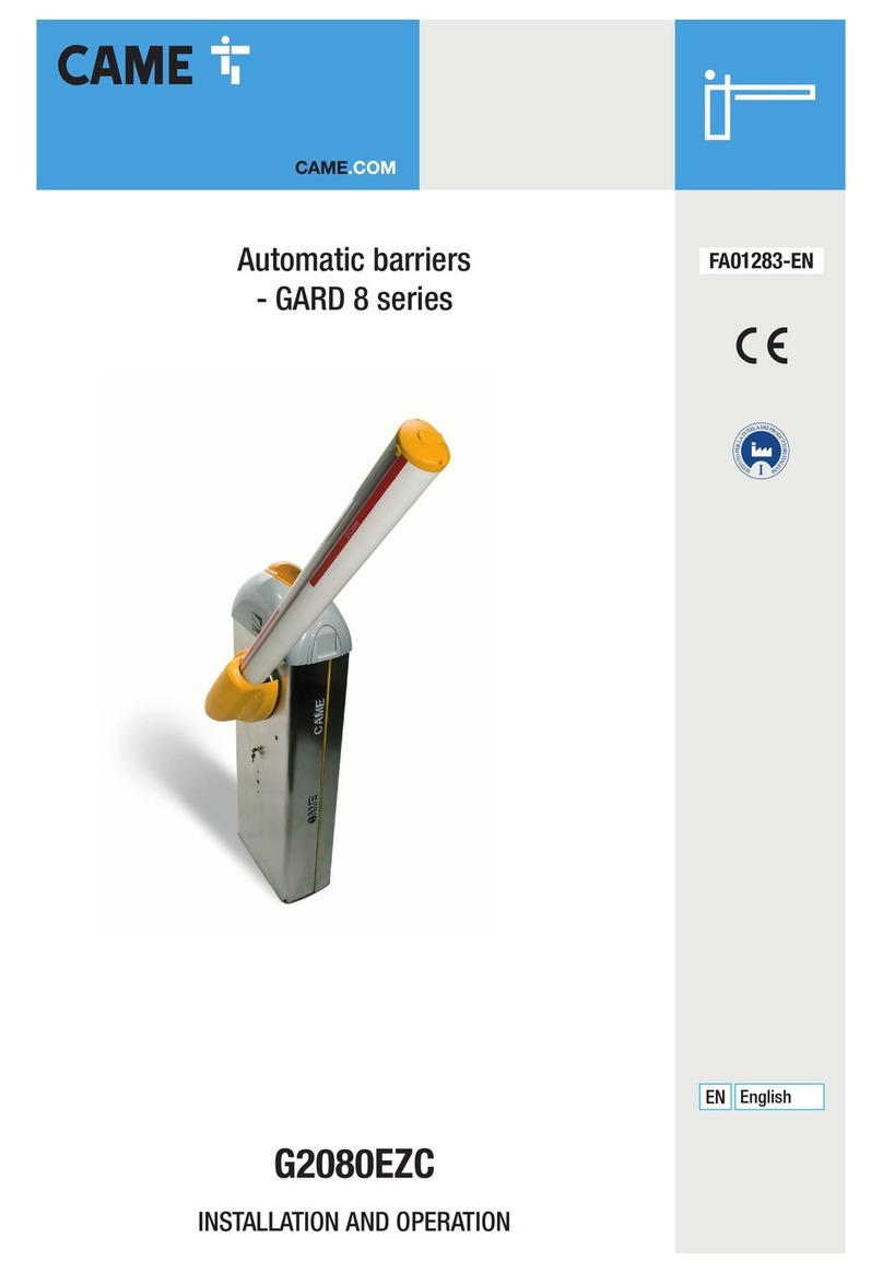
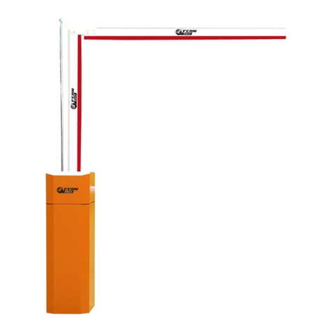
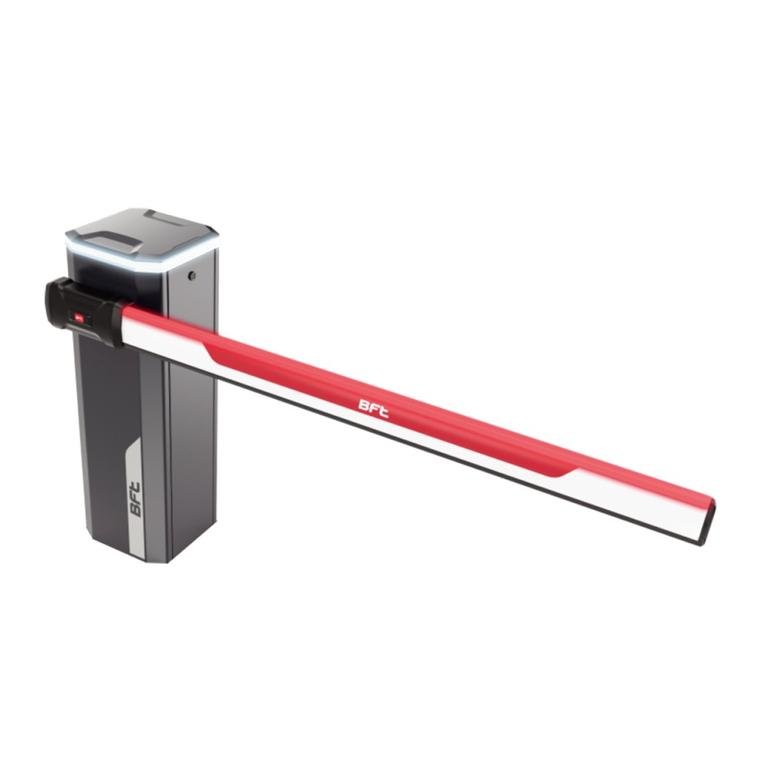
Automatic Barrier
d3250
Made in
the

1. Inductions and warnings Page 03
2. Delivery, Movement and transport Page 04
3. General layout Page 05
4. Foundation Layout Drawing Page 06
6. Guide to Physical installation Page 07 -09
7. Commissioning Certificate Page 10
8. Manual release Page 11
9. Terminal connections Page 12
10. Control panel layout Page 13
11. Using the controller Display Page 14
12. Barrier Parameters Page 15
13. Barrier Timers Page 16
14. Barrier Time clock Page 17
15. Fault finding Page 18-19
16. Barrier Maintenance Page 20
17. Service Log Page 21
18. Technical Data Page 22
Index
D
3250

/ /20
Important Safety Notice
Automatic barriers are designed to Control the flow of vehicular
traffic only. It can be dangerous to allow the passage of
pedestrians and any other self-powered animal or device to
utilise this method of access without appropriate warnings and or
signage.
It may be necessary for the end user of this product to provide
an alternative, safe method of access to cater for the previously
mentioned categories.
The end user should fit all necessary signage and warning
notices to either side of the gate, which should be visible and
clear from all directions of approach.
The product that was shipped to you was designed with a control
program to protect all categories from harm or affect this
however is only a safety precaution and should not be modified
or tampered with by any unauthorised person not sanctioned by
the manufacturer.
Please sign and date below to say that you have read and
understood this notice before ANY installation work:
The “Warnings” leaflet and “Instruction booklet” supplied with this
product should be read carefully as they provide important information
about safety, installation, use and maintenance.
Scrap packing materials (plastic, cardboard, polystyrene etc) according
to the provisions set out by current standards. Keep nylon or polystyrene
bags out of children's reach.
Keep the instructions together with the technical brochure for future
reference.
This product was exclusively designed and manufactured for the use
specified in the present documentation.Any other use not specified in
this documentation could damage the product and be dangerous.
The Company declines all responsibility for any consequences resulting
from improper use of the product, or use which is different from that
expected and specified in the present documentation.
Do not install the product in explosive atmosphere.
The construction components of this product must comply with the
following European Directives: 89/336/CEE, 73/23/EEC, 98/37/EEC
and subsequent amendments. As for all non-EEC countries, the abovementioned
standards as well as the current national standards should
be respected in order to achieve a good safety level.
Information on using
this manual
? Read all information thoroughly
? Pay attention to all safety advice
? Be aware of the symbols (shown above right and
above left) as they have different meanings. One is an
information symbol, the other a warning.
? There are many artists impressions of the product in
this manual you should refer to the images as a guide
only. Professional CAD drawings should be used as
a reference drawing and nothing else. As before every
effort has been made to be 100% accurate in this
manual but we cannot make any guarantees.
? As we constantly innovate our products we may
change the quoted spec and any other details that
have been documented in this manual so you should
always refer to the supplier to see if the manual that
was shipped with your product is the latest edition.
? As with all electrical installations you should use a
qualified electrician and obey all of the latest laws and
regulations.
? Be sure to fill out and complete ALL paperwork where
instructed as this manual is the equipments log book
and maintenance manual.
The Company declines all responsibility for any consequences resulting
from failure to observe Good Technical Practice when constructing
closing structures (door, gates etc.), as well as from any deformation
which might occur during use.
The installation must comply with the provisions set out by the following
European Directives: 89/336/CEE, 73/23/EEC, 98/37/EEC and
subsequent amendments.
Disconnect the electrical power supply before carrying out any work on
the installation. Also disconnect any buffer batteries, if fitted.
Fit an omnipolar or magnetothermal switch on the mains power supply,
having a contact opening distance equal to or greater than 3mm.
Check that a differential switch with a 0.03A threshold is fitted just before
the power supply mains.
Check that earthing is carried out correctly: connect all metal parts for
closure (doors, gates etc.) and all system components provided with an
earth terminal.
Fit all the safety devices (photocells, electric edges etc.) which are
needed to protect the area from any danger caused by squashing,
conveying and shearing, according to and in compliance with the
applicable directives and technical standards.
This equipment is part of a large range of traffic flow products. They are designed to be easy to install, as
all settings and internal wiring have been completed in our factory. Any of the instructions in this manual
should only be carried out by a qualified service engineer or a competent person.
The barriers are ready to bolt down, connect to a single phase power supply and have any pre-cut loops
wired into them (Please note that loop detectors are sold separately). The steps must be completed before
the power is turned on to prevent accidents.
The following information is a guide only, and whilst we have made every effort to be accurate and correct
there may be printing errors which we cannot be held responsible for.
With a correct installation you can expect to enjoy many years of reliable service from this product, we do
however recommend that the product has a bi-annual service carried out by a qualified engineer. Please
contact our service department to obtain a quote. As we manufacture the products we are best suited to
care for your equipment.
Introduction and Warnings
D
3250
Incorrect Correct
This article describes how your equipment will be delivered to you, specifications on the transportation
used and advice including health & safety on movement of the equipment.
The manufacturer will use a qualified transport company to deliver the product conforming to the
necessary regulations as detailed below:
?All drivers are qualified
?All drivers are tested once yearly ( If applicable )
?All drivers carry risk assessments and method statements (available on request)
?They are controlled under law to conform as there are no trade regulation standards to comply with
Health and safety Considerations:
Moving Goods Safely (MGS) is a national project involving both the Health and Safety Executive (HSE) and
Local Authorities (LA) working in partnership. The project aims to reduce injuries and ill-health arising from the
movement of goods from supplier through haulier to the recipient and end user including any home deliveries.
The project will focus upon the delivery and collection of goods and the hazards this generates. It covers the
main areas that cause the majority of injuries and ill-health to workers, including:
?Workplace transport;
?Slips & trips, and;
?Musculoskeletal disorders (MSD).
The movement of goods presents us, as health and safety regulators, with the challenge of dealing with a huge
variety of issues. The commercial organisations involved within the movement of goods are diverse including
haulier, third party logistics providers, pallet networks, retailers etc, with some very large companies,
thousands of small businesses and the self-employed. The movement of goods is more than just trucks on the
road with a large proportion of accidents happening at the delivery/collection sites that are often not directly
under the control of the company making the delivery or collection. Communication and cooperation problems
can arise due to the many organizations involved in the movement of the goods, and this can also lead to
difficulties in effectively managing health and safety.
(Source H&S Executive UK 2008)
The barrier should ALWAYS! be moved with care and attention. The products are very heavy individually
as well as a whole. You should not attempt to move this or any other products by unapproved handling
methods.
Transport and Handling.
D
3250

D210 Dual height access post
Std tip support
D3250 Automatic Barrier
Safety/Lower Loop
Auto exit Loop
Shown below is a typical installation of a D3250 Automatic barrier for a single entrance.
Control - Dual height Card access entry, Loop safety/lower with Auto loop exit.
Shown above is a very basic layout, There are many types of layouts available such as
Separate entry/exit barriers, Twin Barriers for larger span roads and many more.
General Layout.
D
3250

General Layout Foundation drawing.
D
3250

1
When delivered, the barrier will arrive
On a pallet. Make sure you check
Before you sign! Take care when
Unpacking not to damage the barrier.
Once the barrier has been lifted onto the plinth,
Align the pole arm adaptor with the centre of
The tip support. Ensure both barrier and tip
Support are level ready for bolting down.
2
Component Identification and Notes:
You should check that you have received the following in your order as they are referred to throughout this
manual (note this can change per barrier spec i.e. manual components are different from automatic):
Barrier Cabinet
c/w Pole Arm Adaptor
End Rest Pole , if over 6m then it will have
Strainer wire attached to it.
Box of bits C/w
4 x M16 parabolts
4 x M12 parabolts
2 x M6 x 90 pole bolts
1 x cabinet key
O and M manual
O&M Manual
Revision 1.2
Follow the steps below for Installation.
Please note all installations should be carry out by a competent person and all electrical
Connections should be made by a qualified electrician.
Guide to Physical Installation.
Top View
Level
D
3250

3 4
Remove Both Barrier covers using the keys provided
And place the Covers somewhere safe to prevent them
getting damaged. Then using An SDS Drill and M16
drill bit Drill one of the rear fixing holes And knock in one
of the M16 Bolts supplied. You can remove the control
Cabinet to gain access to the fixing holes below it, to
Do this remove the M8 nuts fixed at the rear of the
Panel.
Now make sure all cables are through the duct and
Routed where they need to go (e.g mains cable to
The Isolater.) Then after checking the barrier is
Still in line and level proceed to drill and bolt in the
Rest of the fixing bolts. Once all bolts are in make
Sure they are tightened down.
Guide to Physical Installation. (Cont)
Unwrap the pole very carefully and slide the pole
onto the pole arm adaptor. Using a 6.5mm HSS
Drill bit now drill through both the Pole and the
adaptor at the same time and fit the M6 x 90 Cap
head bolts supplied.
Note - if the pole has boom lights/maglock make
sure you connect these before fitting pole.
5Now the barrier is fully bolted down with the pole on,
Manually wind the barrier in the fully raised and
Lowered positions to ensure everything is correctly
In line.
6
D
3250

7
Notes area
Now connect all Induction loops, Mains power and
Any other accessories you have using the
Connection diagram on page 8. Once you have
Everything connected you can then power up and
test. You must check that all safety accessories
Work correctly first and then move on to testing any
Access control fitted. Below shows a basic keypad
Entry, auto exit and loop lower/safety system.
Depending on pole length you may now be required
To adjust the limit switches if the pole is not finishing In the
desired position. You will see the two Limit strikers on the
main shaft that operate the limit Switches. These are what
you may need to adjust, For example if the pole is stopping
short of its tip Support in the lower position then you will
need to Back the lower striker off so it hits the switch later
Allowing the pole to travel further. Depending on what
handing the barrier
Is depends on which limit switch does the raise or lower.
You will clearly see which one you need to adjust by
looking
At the position of the barrier to the pole.
Make sure to check all your connections and the barrier is earthed correctly. Also ensure the barrier
covers are on correctly and the safety switch is operated. Now fill out the commissioning certificate
on the Next page.
9
D
3250
Guide to Physical Installation. (Cont)
8
earth product
Notes area

We certify that the system covered by this certificate has been commissioned satisfactorily.
Site Name
Site Reference
Installation Commenced / /20
Completion
Engineers Installing
Commissioning
Equipment Fitted
Handover Date
Part 2. Existing Installation Items not covered under warranty/ This certificate:
Installers Name
On Behalf of
Address
Signature
Date of Signing
Position
Part 3. Certificate Signing off Section
Client Name
On Behalf of
Site Address
Signature
Date of Signing
Position
D
3250
Commissioning Certificate.

Electrical Troubleshooting Guide
Please use the following instructions to operate the barrier manually, the following
is assuming you have powered down the unit.
As stated at the beginning of this manual we recommend a bi-annual service, but at a bare minimum, it is imperative
that you get a service done once every 12 months. This is not a sales tactic in disguise, there is a very serious
health and safety issue/risk associated with not complying to this. Also in order for your barrier to keep complying
with the appropriate legislation.
Before carrying out any maintenance to the installation, disconnect the mains power supply.
Make sure you have disconnected/Isolated the power before attempting any work.
A Maintenance Contract should be sought from a specialist company after a maximum of 5000 manoeuvres or 1year from
the install date.
Occasionally clean the photocell optical components and make sure they are free from dirt, water, rain, soil etc.. ? Batteries
in photo cells may need to be changed every 6 months or sooner dependant on use. Barrier will not work properly without
photo cell function.
Have a qualified technician (installer) check the correct setting of the electric clutch.
If the power supply cable is damaged, it must be replaced by the manufacturer or its technical assistance service, or else by
a suitably qualified person, in order to prevent any risk.
When any operational malfunction is found, and not resolved, disconnect the mains power supply and request the
assistance of a qualified technician (installer). When automation is out of order, activate the manual release to allow the
opening and closing operations to be carried out manually.
Gearbox drive unit is “sealed” for life and requires no further lubrication.
!
To Manually release the barrier please remove the cover using key supplied, then take the
release Handle ( which will be handed over with the keys ) and insert into the motor and rotate.
Direction depends on Barrier handing. Once the barrier is wound to the desired position replace
the release key and replace the cover and re-lock.
Note the cover has a safety switch on it that will not allow the barrier to operate if the cover is
Not fully closed.
D
3250
Manual Release.

16 - Connect to terminal 4 in slave barrier
17 - Connect to terminal 5 in slave barrier
18 - Connect to terminal 4 in slave barrier
19 - Connect to terminal 3 in slave barrier
When used as a Master Barrier below terminals will be situated on the din rail
D
3250
Connection Terminals

D
3250
Control Panel layout.
240v Terminals
240v Breaker
24VDC Power supply
PLC
Inverter
Loop Detector
Low voltage terminals
24v Fuse 1Amp
Programming
screen
Above shows a typical barrier control panel layout which identifies the major components

D
3250
Using the Controller Display
D3250 Main Menu
Raise LowerSelect Alarm
Parameters
Time Clocks
Timers
Drive Settings
Motor Settings
The barriers PLC has a remote controller display screen where you
Can change features and operate the barrier. The Installer should
Have the screen or it should be left in the barrier control cabinet.
The Remote display should be plugged into the serial port 1 on the
PLC to enable it to operate the Barrier.
To operate the display you simply use the dial/arrows to navigate
Your way through the screen. There is an ESC key which will take
You back to the home screen if you want to return.
Home
Select Alarm
Controller Setup
Operator Interface
The home screen is always the first
Screen that appears after the gate is
Powered up. You will only ever need
To access operator interface to
Operate and change parameters
Of the barrier.
Once you select operator interface
You will see the screen shown in
The left diagram which shows
Settings you can alter. One very
Useful feature is the R4 and R3
Key can raise and lower the barrier
As shown in the bottom right hand
Of the screen.
D3250 Main Menu
Select Alarm
Parameters
Time Clocks
Timers
Drive Settings
Motor Settings
Using the Arrows/dial navigate the
Cursor to operator interface and
Press ok and you will see the
Parameters menu. Press OK with
The cursor on parameters and all
The parameters will then appear.
Parameters
ON OFF Alarm
Safety Reverse ON
You can now scroll through the
Parameters and choose what you would
Like to turn on. To turn on/off use the
R1/R2 key which is labelled on the screen
in the bottom left corner.
The barriers PLC has various parameters that can be set so you can
Alter the way the barrier operates.
To change the parameters you will need access to the PLC graphic
Display, once you have access to this Follow the below instructions.
No Pass Timer OFF
Loop/Photocell Close ON
Boom Lights OFF
Flashing Boom Lights OFF
D
3250
Setting the barriers parameters
Raise Lower

D
3250
Barrier parameters
Barrier parameters Description Default
No Pass Timer This turns on a timer that times out and lowers
The barrier if no vehicle passes through the loops
Or photocells. This timer is located in Timers.
OFF
Safety Reverse This allows the barrier to raise back up if the loops
Or photocells are activated whilst the barrier is
Lowering.
OFF
Loop/Photocell Close This closes the barrier once the loop or photocells
Have been activated. OFF
Boom Lights This turns the output on for Boom lights to operate,
The lights will turn off in the up position. OFF
Flashing Boom Lights This enables the Boom lights to flash OFF
Slow down This enables the barrier to slow down after a set
Time, The timer for this is located in timers. ON
Inverter Outputs The Plc runs the inverter via a network cable, this
Option turns on the outputs to run an inverter hard
Wired. OFF
Raise Timeclock This turns ON the raise timeclock which will hold the
Barrier up at set times of the day. See timeclock
Setup on page 18.
OFF
Auto Timeclock This turns on the Timeclock that disables the auto
Loop from operating at set times of the day. See
Timeclock set up on page 18.
OFF
N/O Safety This turns the safety input into normally open OFF
Master/slave This turns on the master/slave outputs to operate
A slave barrier from. Q6 = Raise Q7 = Lower OFF
Traffic light This turns on the traffic light output OFF
Kerb Interlock This turns on the kerb interlock program, see your
Supplier for connection/operation details. OFF
2 Step logic The 2 step logic allows the raise input to lower
The barrier once raised.
OFF
Below is a table of all the parameters available to set in the barriers PLC, Please note there may be
Bespoke programs developed for certain companies where the parameters may be differ from below.

D3250 Main Menu
Raise LowerSelect Alarm
Parameters
Time Clocks
Timers
Drive Settings
Motor Settings
To access the timers scroll down
To Timers and press ok, here you
Will see a list of timers that you
Can alter to suit your requirements
Within the barriers plc screen you can set up various timers.
Follow the below instructions to set up.
Accessing Timers
Barrier Timers
Select Alarm
Traffic light delay
No pass delay
Mag delay
Once you are in the barrier timers
Screen you can now select the
Timer you wish to change.
D
3250
Barrier Timers
Lower delay
Slow down delay
Traffic light delay
Lower delay
No pass delay
Slow down delay
Delays the traffic light from going Straight
to green once the gate has fully opened
Delays the barrier from lowering once given a
Close signal from photocells/Button.
When turned on in parameters this timer
Times out and lowers the barrier if no close
Signals are given.
This timer sends the gate into slow speed
After the set time. This must be set to come
In when the gate is around a meter from its
Closing post
Timer
Operation
Mag delay
The time taken to bring in the maglock
Output from when the barrier reaches its
Lower limit.
Raise delay timer This timer delays the barrier from raising.

D
3250
PLC Time clock setting.
D3250 Main Menu
Raise LowerSelect Alarm
Parameters
Time Clocks
Timers
Drive Settings
Motor Settings
Period 1
Using the Arrows/dial navigate the
Cursor to operator interface and
Press ok and you will see the screen
As shown to the left. Now enter into
Time clocks.
Timeclock configuration
Select Alarm
Raise Time Clock
Choose from the two timeclocks
Available which one you would like
To set, press ok and proceed below.
ON OFF
Monday ON
Tuesday OFF
Raise Timeclock
Select Alarm
Period 1 : Time set
Period 1 : Day set
Period 2 : Time set
Period 2 : Day set
Period 3 : Time set
Each period represents an ON/OFF time,
You can now enter up to 4 periods and
Set the times and days you require.
Period 1
Select Alarm
On Time
Off Time
0900
1700
In Range 0
When you select a “period time set” it will
Take you to the on/off time for that
Period, you can now set the times you
Need the barrier to stay open. In Range
Just lets you know if that period is on
Or off ( off being 0 )
When you select a “period day set” it will
Take you to the on/off screen to set which
Days you would like that period to work
Using the the on/off buttons which are
Indicated at the bottom left hand of the
Screen.
Wednesday OFF
Thursday OFF
Friday OFF
The barrier has a built in 24hr time clock with two functions,
Function 1 - Raise Timeclock which holds the barrier up
Function 2 - Auto Timeclock which disables the auto loop
Note, you will need to turn these timers on in parameters once
you have set up them up as below.
Auto exit Time Clock
Example ; Raise timeclock
Tuesday OFF
Follow the same procedure for setting up the auto timeclock.

1. Inputs
Input Polarity Connected to Operation when active
I0 Normally closed Kerb lowered Stops the barrier from raising when kerb interlock ON
I1 Normally Closed Stop circuit Barrier stops if door open
I2 Normally Open Raise signal Raises Barrier
I3 Normally Open Lower signal Lowers barrier
I4 Normally Open Raise limit switch Arm has reached its fully open position
I5 Normally Open lower limit switch Arm has reached its fully closed position
I6 Normally Open Safety loop Detector/Photocell Barrier stops and returns the the raise position until clear.
I7 Normally Open Auto Loop Raises the barrier from the auto loop
2. Outputs
Output: Polarity: Connected to: Operation when active:
Q0 Normally Open Motor controller slow down Active to slow barrier down
Q1 Normally Open Motor controller open direction Active to Raise barrier
Q2 Normally Open Motor controller close direction Active to lower barrier
Q3 Normally Open Boom Lights Active to operate boom lights
Q4 Normally Open Traffic light relay Active when green light in
Q5 Normally Open Maglock or siren Active to operate maglock or siren (depending on parameters)
Q6 Normally Open Slave raise or Barrier raised Active to raise the slave barrier or give barrier raised output
Q7 Normally Closed Slave Safety/close or barrier lowered Active to lower the slave safety or give barrier lowered output
D
3250
Electrical Troubleshooting guide.
The table (bottom) relates to the diagram directly below to help you trouble shoot electrical
component errors
PWR
BAT
RUN
EROR
SD
0
1
2
3
4
5
6
7
0
1
2
3
4
5
6
7
IN OUT
M221 TM221M16R
The image on the left shows the input and output
LED indicators, use these with the chart below
To identify any faults with the barrier. The example
On the left shows that the barrier is lowered, the
Photocells/loop are healthy and the stop circuit is
Also healthy.
Note, the PLC is located in the barrier cabinet.

ELECTRICAL ERRORS CAUSE CORRECTION
MECHANICAL ERRORS CAUSE CORRECTION
Barrier arm keeps going up and down Limit switch fault check and reset limit switches
Barrier creaking when moving Check bearings Oil or grease bearings
Barrier motor not running Loss of voltage Check motor supply test 3 phases
Barrier not raising or lowering Possible stripped gears Call service team to diagnose fault
Barrier not raising or raising half way Gearbox Gears stripped due to overlading replace
Barrier raises slowly and lowers too fast Lack of balance counter weight compensation Fit counter weights
Barrier not running at all Door has been left open or switch not pushed in Close the door and issues a signal to open or
close
Barrier raised will not lower Key switch is left in open position Turn key switch to auto
Loop fault or loop detecting Check if green light is on detector if so remove
object that it is detecting or replace loop
Blank screen on PLC but power to other devices
in the control panel
On-board fuse blown Replace fuse and reset barrier
PLC has developed an electrical fault or had a
power spike
Change PLC
Barrier does not run (stays open)
Check inverter is in ready (rdy) mode on display Power down then back up
Loop detector is faulting or sensing presence Clear obstacle or reset the detector
Check inverter settings ACC - 6.0 DEC – 2.0 LSP – 25-40 (Variable)
Barrier staying up in raise position Access control giving a constant pulse shorten
this
Photo cell batteries (if fitted) Check that the fitted batteries still have power to
them. They should only be replaced with special
3.6V Lithium-ion batteries made for purpose. These
can be provided by your supplier
Photo cells dirty (if fitted) Clean photo cells make sure they are debris free
Mains on but no power Isolator fuse Check and meter fuse in isolator
Barrier not going up Access control may be faulty Remove and check barrier function via the PLC
Barrier Staying up Car has driven off before clearing the loop Complete cycle by going through the ground loop
D
3250
Troubleshooting guide. (Cont.)

As stated at the beginning of this manual we recommend a bi-annual service, but at a bare minimum, it is imperative
that you get a service done once every 12 months. This is not a sales tactic in disguise, there is a very serious
health and safety issue/risk associated with not complying to this. Also in order for your barrier to keep complying
with the appropriate legislation.
Before carrying out any maintenance to the installation, disconnect the mains power supply.
Make sure you have disconnected/Isolated the power before attempting any work.
A Maintenance Contract should be sought from a specialist company after a maximum of 5000 manoeuvres or 1year from
the install date.
Occasionally clean the photocell optical components and make sure they are free from dirt, water, rain, soil etc.. ? Batteries
in photo cells may need to be changed every 6 months or sooner dependant on use. Barrier will not work properly without
photo cell function.
Have a qualified technician (installer) check the correct setting of the electric clutch.
If the power supply cable is damaged, it must be replaced by the manufacturer or its technical assistance service, or else by
a suitably qualified person, in order to prevent any risk.
When any operational malfunction is found, and not resolved, disconnect the mains power supply and request the
assistance of a qualified technician (installer). When automation is out of order, activate the manual release to allow the
opening and closing operations to be carried out manually.
Gearbox drive unit is “sealed” for life and requires no further lubrication.
D
3250
Barrier Maintenance
Table of contents