ZKTeco SBTL300 Series User manual

SBTL300 Series
User Manual
P a g e | 1 Copyright© 2020 ZKTECO CO., LTD. All rights reserved.
Thank you for choosing our product. Please read the instructions carefully
before operation. Follow these instructions to ensure that the product is
functioning properly. The images shown in this manual are for illustrative
purposes only.
User Manual
Swing Barrier-SBTL300 Series
Date: September 2020
Doc Version: 1.0
English

SBTL300 Series
User Manual
P a g e | 1
About the Manual
This manual introduces the operations of SBTL300 Series product.
All figures displayed are for illustration purposes only. Figures in this manual may not be exactly
consistent with the actual products.

SBTL300 Series
User Manual
P a g e | 2
Document Conventions
Conventions used in this manual are listed below:
GUI Conventions
For Software
Convention
Description
Bold font
Used to identify software interface names e.g. OK, Confirm, Cancel
>
Multi-level menus are separated by these brackets. For example, File > Create >
Folder.
For Device
Convention
Description
< >
Button or key names for devices. For example, press <OK>
[ ]
Window names, menu items, data table, and field names are inside square
brackets. For example, pop up the [New User] window
/
Multi-level menus are separated by forwarding slashes. For example,
[File/Create/Folder].
Symbols
Convention
Description
This implies about the notice or pays attention to, in the manual
The general information which helps in performing the operations faster
The information which is significant
Care taken to avoid danger or mistakes
The statement or event that warns of something or that serves as a
cautionary example.

SBTL300 Series
User Manual
P a g e | 3
Table of Contents
1PRODUCT INTRODUCTION..........................................................................................................4
CHASSIS DESIGN AND DIMENSIONS ............................................................................................................................................... 4
MECHANICAL SYSTEM OF THE SWING BARRIER ............................................................................................................................. 5
ELECTRONIC CONTROL SYSTEM ....................................................................................................................................................... 5
SYSTEM COMPOSITION OF THE PRODUCT ...................................................................................................................................... 5
SPECIFICATION ................................................................................................................................................................................... 6
2INSTALLATION OF THE PRODUCT ..............................................................................................7
INSTALLATION NOTES ....................................................................................................................................................................... 7
INSTALLATION POSITION OF THE SWING BARRIER......................................................................................................................... 7
CABLES INSTALLATION AND FIXING................................................................................................................................................. 8
3MENU INTRODUCTION ................................................................................................................9
FUNCTION INTRODUCTION............................................................................................................................................................... 9
OPERATING INSTRUCTIONS.............................................................................................................................................................10
MENU INTRODUCTION....................................................................................................................................................................10
4TROUBLESHOOTING...................................................................................................................13
5PRODUCT MAINTENANCE .........................................................................................................13
CHASSIS MAINTENANCE .................................................................................................................................................................13
MOVEMENT MAINTENANCE...........................................................................................................................................................13
POWER MAINTENANCE....................................................................................................................................................................14
APPENDIX INTERNAL WIRING DIAGRAM.......................................................................................15

SBTL300 Series
User Manual
P a g e | 4
1Product Introduction
Chassis Design and Dimensions
SBTL300 series comes with SUS304 housing which provides simple and beautiful design with
corrosion protection. It provides legal access to the persons and restricts illegal personnel access. In
case of emergency, it ensures that evacuation passage runs smoothly and is convenient for
personnel.
SBTL300’s appearance and dimensions are shown in Figure 1-1:
Figure 1-1

SBTL300 Series
User Manual
P a g e | 5
Mechanical System of the Swing Barrier
The mechanical system of a swing barrier turnstile includes the chassis and the core component. The
chassis is a carrier where the direction indicator, the reader, the Infrared sensor, and the door lock
are installed. The core component mainly consists of the motor, the frame, the belt, and the swing
arm.
Electronic Control System
The electronic control system of a swing barrier turnstile is mainly composed of the reader, the
master control panel, the infrared sensor, the direction indicator and the alarm.
Reader (optional): The reader reads the data in the card and sends it to the controller.
Master control panel: The master control panel is the system’s control center that receives signals
from the reader and the photoelectric switch, performs logical judgment and processing of these
signals, and sends executive commands to the direction indicator, the electric motor and the alarm.
Infrared sensor: It detects the position of a pedestrian and plays the role of safety protection.
Direction indicator: This indicator displays the pedestrian passage path, and directs them to pass
through the lane in a safe and orderly manner.
Alarm: The alarm gives an alarm voice if the system detects any unauthorized entry to the lane.
System Composition of the Product
The single-lane management system is composed of two single-core swing barriers. The multi-lane
management system is composed of two single-core barriers and multiple dual-core barriers.
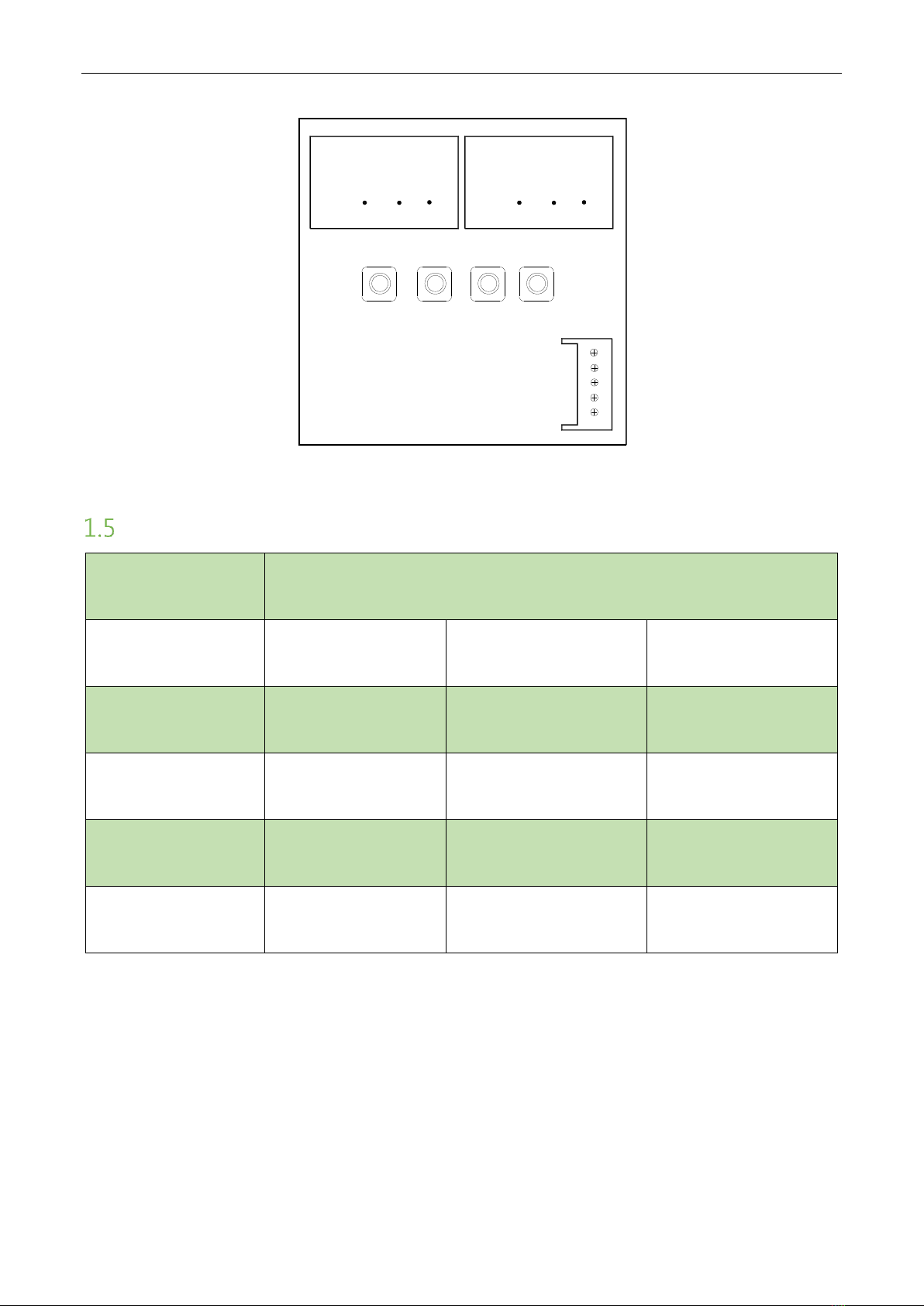
Working modes of the system
To make the product more versatile, this system provides multiple working modes for the user,
including normal working mode, normally open and normally close mode, testing mode. After
supplying power to the device, the digital screen on control board will display a default state, which
displays current work mode.
There are 4 operation buttons on the keypad, "MENU", "MODE", "ADD" and "DEC". (Figure 1-2)

SBTL300 Series
User Manual
P a g e | 6
Figure 1-2
Specification
Dimension(mm)
SBTL300 Series: L = 1200, W = 200, H =981.50
Communication
RS485
Input voltage
AC110~240V, 50-60Hz
Input control signal
Switching signal
Output voltage
DC 24V
Time of
opening/closing
0.8 Sec (adjustable)
Relative humidity
20% - 95%
(Non-condensing)
Temperature
-28℃to 60℃
Passage rate
Maximum 30/minute
Infrared sensor
4
Working environment
Indoor
J4
888
888
DEC
ADD
MODE
MEUN
GND
C
D
S
5V

SBTL300 Series
User Manual
P a g e | 7
2Installation of the Product
Installation Notes
1) It is recommended that the swing barrier must be installed on a horizontal solid platform with a
height of 50mm to 100mm.
2) It is also recommended that the swing barrier turnstile should not be used in corrosive
environment.
3) Make sure the protective ground wire of the system is reliably connected to avoid personal
injuries or other accidents.
4) After installation, check if the connection is done correctly at the connecting points of the
protective ground wire, at the connector assemblies and wiring points of the circuits, as well as
at each movable part of the swing barrier turnstile. Any loose nuts, screws and other fasteners
should be tightened in time to avoid swing barrier turnstile failures caused by longer operations.
Installation Position of the Swing Barrier
A distance of 100mm between the swing barrier turnstile and the wall needs to be reserved for ease
of opening the top cover of the machine to perform maintenance and adjustment. The reference
figure is shown below:
Figure 2-1 SBTL300 series dual-lane

SBTL300 Series
User Manual
P a g e | 8
Cables Installation and Fixing
For the outlets of the concealed cables, please refer to the drawing indicating the mounting holes.
The input voltage for this swing barrier turnstile is AC100-120V/200-240V and its master and slave
are connected by a 3-core cable (signal) and a 2-core cable (power). When installing the swing
barrier turnstile, the user only needs to connect it to the corresponding ports. Note that the PVC
conduits are laid 100mm under the ground, with the height of the exposed part not exceeding
100mm. In addition, the conduit outlet is bent back to prevent ingress of water into the conduit.
SBTL 300 series installation holes and cabling positions is shown in Figure 2-2:
Figure 2-2
Mark the screw hole at the centre of the stand, and the edge of the chassis base on the ground
according to the sizes as shown on the Figure 2-2. Use a hammer drill to make M12 screw holes and
then install the screws. Place the swing barrier turnstile according to the sizes and positions as
shown in the figure before installation and fixing. Connect the online cables and perform the power-
on test. If the test is OK, tighten the screws. It is recommended that a warning line be marked on the
ground after installing the device, so as to prompt the pedestrian to stand behind the warning line
when swiping the card. As shown in Figure 2-3:
100.00 190.00 707.00 190.00 100.00
1287.00
300.00 50.00300.00
φ25PVCpipe
100.00 ExpansionScrew
Devices

SBTL300 Series
User Manual
P a g e | 9
Figure 2-3
3Menu Introduction
Function Introduction
1. It has clear traffic direction indication function, which indicates whether it can pass or not in the
form of intuitive LED light indication (additional direction light board is required).
2. It has anti tailing function: the system will alarm automatically when it detects the following
phenomenon in the channel (the person behind is close to the person in front, intending to pass
without swiping the card).
3. There are a variety of working modes to choose from, including one-way traffic, two-way traffic,
infrared switch on or pass control through the main board switch on signal (additional control
system, access control, fingerprint, etc.) can be set through the main board menu.
4. It has the function of automatic reset: when the passer fails to pass within the specified time after
receiving the opening signal, the system will automatically cancel the current access authority of
the user, and the restricted passage time can be set in the main board menu.
5. It has voice prompt function.
6. It has the function of zero position self-check, which is convenient for users to maintain and use.
7. It has the function of anti-pinch. When the personnel are passing through and the set passage
time has arrived, it can prevent the swing arm from closing and injuring people.

SBTL300 Series
User Manual
P a g e | 10
8. It has 485 and 232 serial port communication function, and can control the gate opening through
485/232 serial port. After powered on, the digital screen on the control board will display the
default state showing the current working mode.
Operating instructions
1. There are 4 operation keys on the key board, namely "MENU", "MODE", "ADD" and "DEC".
2. Key operation instructions:
•The first button on the menu control panel is the menu button. Long press to enter the menu
options;
•Enter the menu and press the second key to select the menu function;
•The third and fourth keys are menu function value options, which can adjust function
parameters up and down. After adjustment, long press the first key to save parameters;
•Short press the first or second key to open the brake manually.
Menu Introduction
Item
Name
Menu
Function
Description
1
01EXXX
Display mode
0 -- display the
current position of
barriers (default
value: 0)
1 -- infrared input
signal
2 -- control input
signal
3 -- Test Mode
Display description: XFX.XXX
1. Equipment status
2. Equipment status
3. Display status
4.5.6--Display the gate position
in mode 0 (the test mode
displays "---")
2
02EXXX
Opening mode
0 -- right controlled,
left controlled
(default value: 0)
1 -- right prohibition
and left prohibition
2 -- right controlled,
left forbidden
3 -- right forbidden,
left controlled
4 -- right free, left
controlled
5 -- right free, left
prohibition
6 -- right free, left
free

SBTL300 Series
User Manual
P a g e | 11
7 -- right prohibition,
left free
8 -- right controlled,
left free
3
03EXXX
Speed of barrier
opening
0~30 (default: 15)
The higher the number, the faster
the speed
4
04EXXX
Opening brake
stroke
10~25 (default: 25)
The larger the number, the
longer the deceleration time and
the smoother the swing arm
5
05EXXX
Brake speed of
opening
0~30 (default: 10)
The larger the number, the
slower the speed when
decelerating, and the more stable
the swing arm is
6
06EXXX
Speed of barrier
closing
0~30 (default: 15)
The higher the number, the faster
the speed
7
07EXXX
Closing brake stroke
10~25 (default: 25)
The larger the number, the
longer the deceleration time and
the smoother the swing arm
8
08EXXX
Brake speed of
closing
0~30 (default: 10)
The larger the number, the
slower the speed when
decelerating, and the more stable
the swing arm is
9
09EXXX
Master and vice
machines Setting
0 -- master (default:
0) 1 -- vice
10
10EXXX
RS485 address
0~250
11
11EXXX
Open duration
0~60 (default: 5)
Unit: s
12
12EXXX
Gate closing delay
time
0~60 (default: 0)
Unit: s
13
13EXXX
Barrier positioning
1 -- Zero position
(default)
2 -- Left opening
position
3 -- Right opening
position
4 -- Vice opening
position
The corresponding position can
only be adjusted in place

SBTL300 Series
User Manual
P a g e | 12
14
14EXXX
Memory function
0 -- Closing memory
function (default: 0)
1 -- Opening memory
function
15
15EXXX
Swiping card mode
0 -- Allow to swipe
card in passage
(default: 0)
1 -- Not allow to
swipe card in passage
16
16EXXX
Volume setting
0~31 (default: 20)
The higher the value, the louder
the sound
17
17EXXX
Alarm mode
0 -- Opening alarm
voice (default: 0)
1 -- Closing alarm
voice
18
18EXXX
Exchange entrance
and exit voice
0 -- Right entrance,
left exit (default: 0)
1 -- Left entrance,
right exit
19
19EXXX
Traffic detention
alarm time
5~30 (default: 10)
Unit: s
20
20EXXX
Intensity adjustment
10~60 (default: 40)
The greater the value, the greater
the force
21
21EXXX
Fire signal setting
0 -- Right opening
(default: 0)
1 -- Left opening
22
22EXXX
Failure to pass
infrared completely,
delay closing time
5~60 (default: 15)
23
23EXXX
Reset
1 –Reset (default: 0)

SBTL300 Series
User Manual
P a g e | 13
4Troubleshooting
Number
Failure description
Analysis and solution
1
No response from direction
indicator or indication is not
correct.
Check whether the connection of the roof lamp
is correct or not.
2
After swiping the card, there is only
a swing arm action.
Check the master and slave machine type setting
and the 3-core, 2-core connection line.
3
Delay in barrier opening doesn’t
close.
Check whether the time of the opening is too
long or the IR sensor is covered.
4
Motor doesn’t rotate, the
resistance is much, or the belt is
loose.
The motor works properly, but the rotated angle
is not sufficient, so it may cause loosening of
belt.
5
When powered ON, the swing
doesn’t return to the initial
position.
Ensure that no obstacle is in the sensing area,
then restart the equipment.
5Product Maintenance
Chassis Maintenance
The chassis is made up of SAE 304 stainless steel. If it is in service for a longer period, then there
may be rust stains on its surface, regularly sand the surface along the grain softly and carefully. Coat
the surface with anti-rust oil, do not cover the infrared sensor.
Movement Maintenance
Switch off the power supply before maintenance. Open the door, clean surface dust, lubricate the
transmission mechanism. Check the belt movement, if found loose, adjust the position of the motor
to tighten the belt. Check and tighten others connection parts.

SBTL300 Series
User Manual
P a g e | 14
Power maintenance
Switch off the power supply before maintenance. Check the plug connection, if found loose, fix it
properly. Do not change any connection position randomly. Check the external power supply
insulation periodically. Do periodic check for any king of leakage. Check if the technical parameters
of interface are normal. Check the service life of the electronic components and replace accordingly.
Caution: Above mentioned maintenance method for swing barrier must be carried out by
professional personnel. Especially the movement and the electric control part, first switch off the
power supply, ensure the operation safety.

SBTL300 Series
User Manual
P a g e | 15
Appendix Internal Wiring Diagram
Table of contents
Other ZKTeco Automatic Barrier manuals

ZKTeco
ZKTeco BG500 Series User manual

ZKTeco
ZKTeco CMP-200 Series User manual

ZKTeco
ZKTeco FBL200 User manual

ZKTeco
ZKTeco CMP-300 User manual

ZKTeco
ZKTeco ProBG3000 Series User manual

ZKTeco
ZKTeco BGM1000 Series User manual

ZKTeco
ZKTeco BG1000 Series User manual

ZKTeco
ZKTeco BG1045L-LED User manual

ZKTeco
ZKTeco PB3000 Series User manual

ZKTeco
ZKTeco SBTL2000 User manual