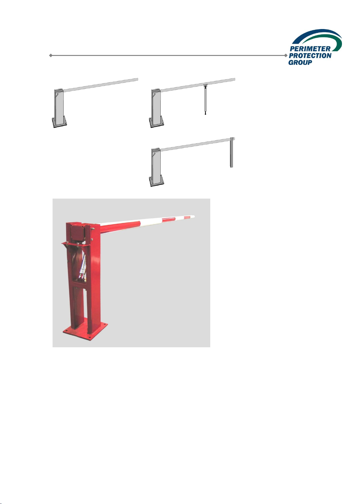
Hand-operated boom barriers Type GHS
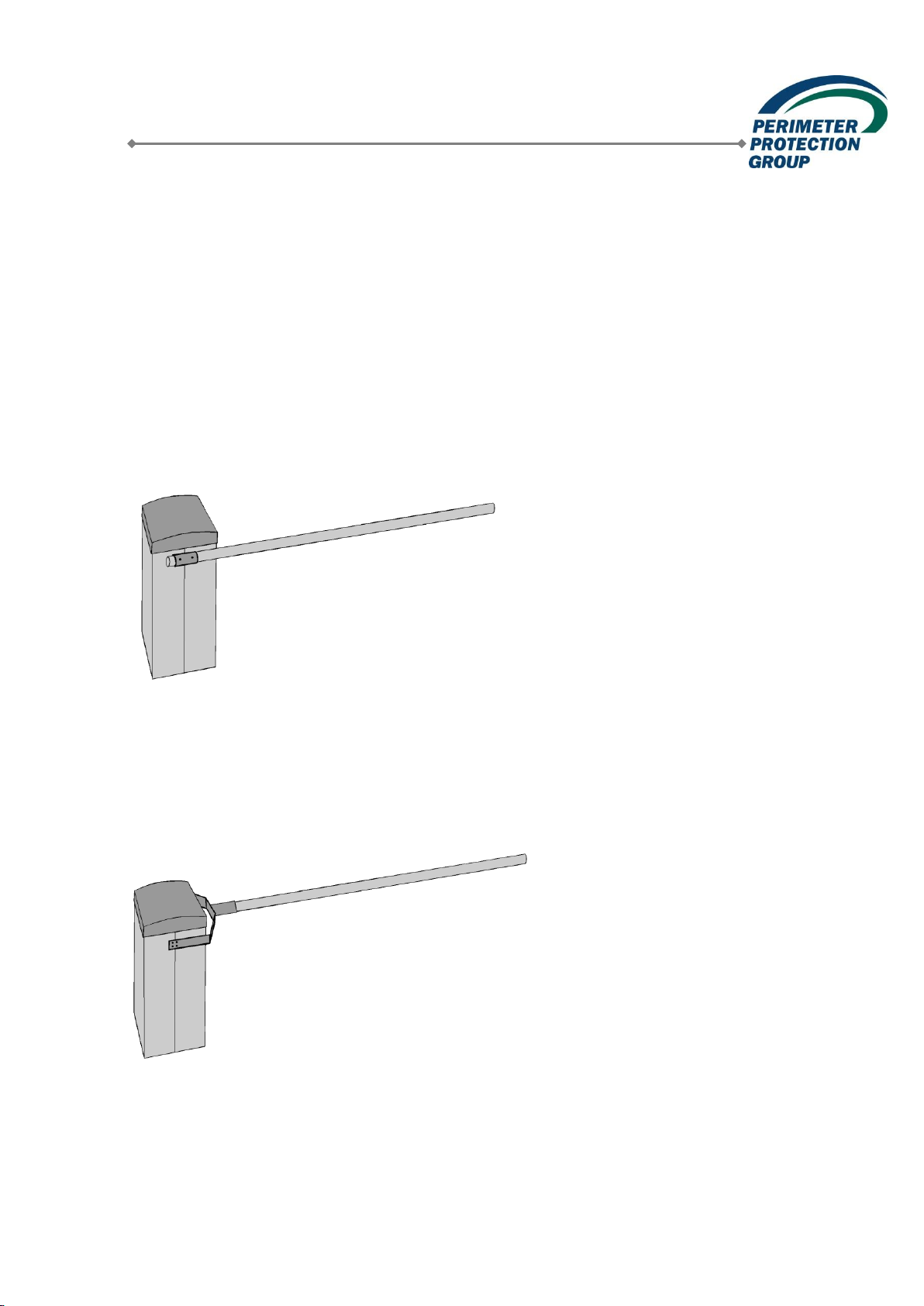
Electrically operated boom barriers Type GES
Electro-hydraulically operated boom barrier Type GEHS
Perimeter Protection Germany GmbH
Document: 2050274 Created: 11.04.2011
Version: a Changed: 15.08.2013 Page 2 of 93
Original version Subject to change
Table of Contents
1. Identification.......................................................................................................................4
2. Main Features....................................................................................................................5
2.1 Appropriate Use ...........................................................................................................5
2.2 Product Description......................................................................................................5
2.2.1 Hand-operated boom barriers................................................................................6
2.2.2 Electrically and electro-hydraulically operated boom barriers...............................10
2.3 Declaration of Conformity / Incorporation....................................................................20
2.3.1 Relevant regulations that the boom barrier systems comply with.........................21
2.4 Environmental Compatibility.......................................................................................21
3. Technical Data.................................................................................................................22
3.1 Hand-operated boom barrier 2 –8 m..........................................................................22
3.2 Hand-operated boom barrier with pendulum support 2 –8 m.....................................22
3.3 Hand-operated boom barrier with fixed support post 2 –8 m......................................23
3.4 Electrically operated boom barrier 2 to 4 m ................................................................25
3.5 Electrically operated boom barrier with pendulum support 2 to 4 m............................25
3.6 Electrically operated boom barrier with fixed support post 2 to 4 m ............................26
3.7 Electrically operated boom barrier with pendulum support 5 to 8 m............................28
3.8 Electrically operated boom barrier with fixed support post 5 to 8 m ............................29
3.9 Electro-hydraulically operated barrier with pendulum support 3 to 6 m............................31
3.10 Electro-hydraulically operated barrier with fixed support post 3 to 6 m.............................33
4. Transportation and Storage .............................................................................................35
4.1 Transportation............................................................................................................35
4.2 Storage ......................................................................................................................35
5. Installation of the Boom Barriers......................................................................................36
5.1 Identification of Components......................................................................................36
5.2 Preparations...............................................................................................................37
5.3 Installation Materials...................................................................................................38
5.4 Installation of the Hand-operated Boom Barrier Type GHS ........................................39
5.4.1 Fastening the boom barrier on the foundation...................................................... 39
5.4.2 Aligning the barrier............................................................................................... 39
5.5 Installation of the Electrically Operated Boor Barrier Type GES and the Electro-
hydraulically Operated Boom Barrier Type GEHS............................................................40
5.5.1 Fastening the boom barrier onto the foundation...................................................40
5.5.2 Aligning................................................................................................................43
5.5.3 Electric connections............................................................................................. 45
5.6 Installation of the Pendulum Support..........................................................................46
5.7 Installation of the Fixed Support Post.........................................................................47
5.7.1 Installation of fixed support post with base plate ..................................................47
5.7.2 Installation of the fixed support post in sleeve foundation.....................................48
6. Putting the Boom Barrier into Operation...........................................................................48
6.1 Hand-operated boom barriers.....................................................................................49
6.2 Electrically and Electro-hydraulically Operated Boom Barriers ...................................50
6.2.1 Basic functions.....................................................................................................50
.....................................................................................................................................50
6.2.2 Control unit ..........................................................................................................51
6.2.3 Checking proper function..................................................................................... 59
7. Operating Manual ............................................................................................................60
7.1 Important Safety Notices ............................................................................................60
7.2 Identification of Components......................................................................................61
7.3 Basic Functions..........................................................................................................62