Centurion CP71 User manual

Latest Revision: 15.03.2004
Document Ref.: 1012.D.01.0001_5
Product Code: CP71
CENTRY
TRAFFIC
BARRIER
INSTALLATION
MANUAL

22

33
1.0 INTRODUCTION
2.0 BASIC KIT
3.0 RECOMMENDED TOOLS
4.0 TYPES OF BOOMS - SIMPLEX / COMPLEX
4.1 CENTRY PRE-TENSION SPRING
4.2 DETERMINATION OF OPERATIONAL MODE
5.0 BOOM ORIENTATIONS
6.0 CABLE REQUIREMENTS - SIMPLEX / COMPLEX
7.0 INSTALLATION
7.1 POSITIONING
7.2 BOLTING DOWN ARRANGEMENT
7.3 REPOSITIONING GEARBOX IN ENCLOSURE
7.4 CHANGING ARC OF TRAVEL ( IF REQUIRED )
7.5 BOOM ASSEMBLY
8.0 ELECTRICAL CONNECTIONS
8.1 SIMPLEX
8.1.1 MAINS SUPPLY
8.1.2 TRIGGER INPUT
8.1.3 SAFETY BEAM
8.1.4 COURTESY LIGHT
8.2 COMPLEX
8.2.1 MAINS SUPPLY
8.2.2 MEMORY INPUT ( MI )
8.2.3 CLOSING LOOP ( OR BEAM ) INPUT
8.2.4 FREE EXIT LOOP
8.2.4.1 LOOP DETAILS
8.2.5 NON - MEMORY INPUT ( NMI )
8.2.6 TICKET VEND INTERLOCK ( T.V.I )
9.0 COMMISSIONING
10.0 DIAGNOSTIC LEDS
11.0 MANUAL RELEASE
12.0 MAINTENANCE
13.0 WIRING DIAGRAMS
14.0 SPECIFICATIONS
15.0 GLOSSARY
Page 5
Page 5
Page 6
Page 6
Page 6
Page 7
Page 8
Page 9
Page 11
Page 11
Page 13
Page 16
Page 18
Page 19
Page 19
Page 20
Page 20
Page 21
Page 21
Page 21
Page 22
Page 23
Page 24
Page 25
Page 25
Page 26
Page 31
Page 31
Page 32
Page 35
Page 37
Page 38
CENTRY TRAFFIC BARRIER
TABLE OF CONTENTS

44

2.0 BASIC KIT
1.0 INTRODUCTION
The boom kit comprises of one or more components shown in the identification list
below.
NB. Mounting rawl bolts are not included (use 4 x M16x150)
HOLDING DOWN ANGLESKID PLATES
35 A/H LOW
MAINTENANCE
PLEASE READ THE INSTRUCTIONS CAREFULLY
55
ELECTRONICS
CP88 CONTROLLER
3m BOOM ARM
4.5m BOOM ARM
STANDARD CHARGER
TRANSFORMER
BATTERY
ENCLOSURE & GEARBOX COMPONENTS
MOUNTING HARDWARE ( PART OF GEARBOX AND ENCLOSURE)
35AH BATTERY35AH BATTERY
--
++
A CENTURION ACCESS AUTOMATION system is a quality product designed to give many
years of trouble free service.
This MANUAL has been compiled to assist you, the customer, with a trouble free
installation.
11 PIN
MAINS FAIL
RELAY
LOOP
DETECTOR
UNIT
ENCLOSURE AVAILABLE IN MILD OR STAINLESS STEEL

ref. 1012034A.cdr
3.0 RECOMMENDED TOOLS
MASONRY BITS
16mm
SPANNER
1 x 10mm/2 x 13mm
1 x 17mm/1 x 19mm
SCREW DRIVER
3,5mm FLAT
No 1. PHILLIPS
CRIMPING TOOL
AND PIN LUGS
PLIERS/SIDE
CUTTER
HAMMER
TAPE MEASURE
ALLEN KEYS
3mm ACROSS FLATS
10mm ACROSS FLATS
HACKSAW
SOLDERING IRON
PICK
SPADE
ELECTRIC
DRILLING
MACHINE
4.0 TYPES OF BOOM
4.1 CENTRY PRE-TENSION SPRING
ARM LENGTH
There are two standard arm lengths available:
OPERATIONAL MODES
Two standard operational modes are available:
SIMPLEX (sometimes called Domestic) - Use BMDV1.X firmware
COMPLEX (sometimes called Commercial) - Use BMCV3.X firmware
The mode is determined by the microprocessor fitted to the CP88 control card as well as
selecting which loop detectors are required, (See next section)
3m
4.5m
66
L
3.0m Barrier L=80mm
4.5m Barrier L=20mm
CENTRY PRE-TENSION SPRING
Adjust according to boom
Pole Length
3.0m Pole: L=80mm
4.5m Pole: L=20mm

77
4.2 DETERMINATION OF OPERATIONAL MODE

88
WALL
WALL WALL
WALL WALL
FRONT
VIEW
FRONT
VIEW
VEHICLE DIRECTION
DEFAULT ORIENTATION
PLAN VIEW
PLAN VIEW
PLAN VIEW
PLAN VIEW
ORIENTATION 2
REVERSED
ORIENTATION 2ORIENTATION 1
ORIENTATION 4
REVERSED
ORIENTATION 4ORIENTATION 3
ORIENTATION 1
REVERSED
ORIENTATION 3
REVERSED
VEHICLE DIRECTION
VEHICLE DIRECTION
FRONT
VIEW
FRONT
VIEW
WALL
VEHICLE DIRECTION
5.0 ORIENTATIONS
ORIENTATION 3 & 4
ORIENTATION 1 & 2
The following orientations are possible:-
The factory default is Orientation 2 for single barriers. See section 7.3 for details of converting to other
orientations.
If barriers are to be paired, (e.g. in a wide entrance of say 6 metres, which requires 2 x 3metre booms,
then the pairs must be selected as Orientation 1 & 2 or Orientation 3 & 4 (i.e. where the doors will open
onto the pavement and not onto the driveway).

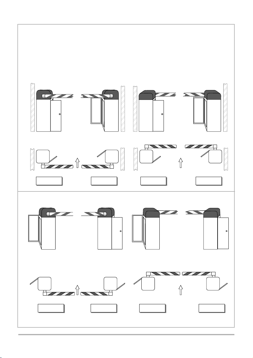
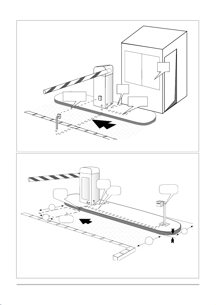
6.2 COMPLEX (Commercial) (Basic Application)
No Ticket Spitter
6.0 CABLING REQUIREMENTS
EI
D RC TOFI ON
ER A V L
T
EI
D RC TOFI ON
ER A V L
T
INFRARED BEAM
(OR LOOP)
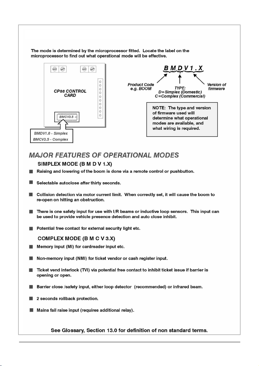
Before doing any cabling, check which operational
mode is required for the barrier. (See Section 4.1)
NOTE: 1. Guard controls operation of barrier using
pushbutton inside guardhut.
99
RESTRICTING KERB
3,5M
1M1M
100100
LOOP
WIRE
FEED
2M2M
CLOSING
LOOP
1M1M
POWER
220V
20mm
CONDUIT
CARD READER
/ KEYPAD
CABLING TO
PUSHBUTTON
GUARD
HUT
220V AC
INPUT
6.1 SIMPLEX (Domestic) (Typical Application)
IMPORTANT :
2. Infra red safety beam can be replaced with inductive loop detector, fitted to the "safety loop" relay base
3. Fit BMDV1.X microprocessor to CP88 control card.
NOTE - 1. Loop detector is fitted to "safety loop" relay base.
- 2. Card reader is connected to MI input.
- 3. Fit BMCV3.X microprocessor to CP88 control card.

1010
6.2 COMPLEX (Commercial)
Access to parking area with ticket spitter
RESTRICTING KERB
4M
min
4M
min
3,5M
1M1M
100100
LOOP
WIRE
FEED
2M2M
TICKET
SPITTER
CLOSING
LOOP
1M1M PRESENCE
LOOP
1M1M
1M1M
POWER
220V
20mm
CONDUIT
CARD READER
/ KEYPAD
6.3 COMPLEX ( APPLICATION WITH FREE EXIT LOOP -
BI-DIRECTIONAL TRAFFIC )
RESTRICTING
KERB
NOTE: For unidirectional traffic
see 8.2.4.1 .
NOTE: 1. THIS DISTANCE MUST BE LESS THAN A CAR LENGTH, IF BI DIRECTION TRAFFIC
IS REQUIRED.
2. USE BMCV3.X MICROPROCESSOR.
3. FIT BOTH SAFETY, AND FREE EXIT LOOP DETECTORS.
NOTE: 1. " CLOSING " loop detector is fitted to " Safety loop " relay base;
2. " Presence " loop is part of ticket spitter;
3. Fit BMCV3.X microprocessor to CP88 control card.
SAFETY / CLOSING
LOOP
EXIT
DIRECTION
FREE
EXIT
LOOP
1m 1m
2m
1m
1m

1111
Cable
entry
area
Skid
plate
Access
door
~164
200
230
7.1 POSITIONING
7.0 INSTALLATION
Determine correct position for barrier .
Check orientation of door - see Section
5.0
Prepare hole for concrete foundation
500 x 500 x 300mm.
300mm
CABLE
ENTRY
AREA
(See section
7.2)
500mm
500mm
7.2 BOLTING DOWN ARRANGEMENT
7.2.1 Alternative 1
EITHER OR
ANCHOR
BOLTS
M16
CABLE
ENTRY
AREA
CONCRETE
SLAB
M16 x 150
RAWL BOLTS
- Throw concrete slab approximately
500 x 500 x 300 mm deep;
- Install cable conduits, make sure
conduits exit in cable entry area.
- Leave approximately 50 mm of conduit
protruding above concrete base;
- Concrete in anchor bolts or fit rawl
bolts later. Use skid plates as templates for
anchor / rawl bolt positioning, if required.
SKID PLATE
HOLDING
DOWN
ANGLE
CABLE
CONDUIT
M16X150
RAWL
BOLTS
NOTE: Enclosure base is clamped
between skid plates and
holding down angles.
APPLY GREASE TO CONTACT
AREA OF TOP OF SKID PLATE
AND BOTTOM OF HOLDING
DOWN ANGLE

CABLE
ENTRY
AREA
CONCRETE
SLAB
- Before pouring the concrete ensure that
the mounting plate is positioned correctly.
- The plate is not symmetrical. The two nuts
closest to the plate edge face towards the
door of boom enclosure.
- Tighten top and bottom nut to aid in
positioning the plate when the
concrete is poured.
- Place the plate above surface of concrete.
- Leave the concrete to dry.
- Unscrew the nuts and washers, and
remove them.
- Arrange enclosure in position and
clampe it between the mounting plate
and the holding down angle supplied
using the nuts and washers that were
removed.
BASE
PLATE
HOLDING
DOWN
ANGLE
M12 NUTS &
WASHERS
1212
7.2.2 ALTERNATIVE 2
Nut Closest to edge
CABLE
CONDUIT

13
7.3 REPOSITIONING GEARBOX IN ENCLOSURE
( To convert a factory default orientation 2 to orientation 4 )
The following modifications are done only if it is necessary to change the
orientation of the gearbox inside the enclosure e.g. the unit has been incorrectly
ordered, or site conditions have changed.
Remove M6 x 10
bolts holding
gearbox to enclosure
Remove cables
linking
motor and limit
switch to CP88
control card
Remove bolts
and nuts securing
cross brace to
gearbox assembly
1 2 3
Step Step Step
CAPTIVE PLATE
GEARBOX ASSEMBLY
1
Step
CABLE
CONNECTOR
TO CP88
CONTROL
CARD
Step
Cross Bar
3
2
Step

14
ROTATE 180
o
ENCLOSURE ENCLOSURE
45
5
6
6
Step Step
Step
Step
Step
o
Lift gearbox
assembly out of
the enclosure.
Rotate the
gearbox through
180
Refit the
gearbox back
into the
enclosure
4
Step
REPOSITIONING GEARBOX IN ENCLOSURE ( Continued )

1515
REPOSITIONING GEARBOX IN ENCLOSURE ( Continued )
Reconnect the
cable
Bolt gearbox
back onto
enclosure
Tighten
cross brace
7 8 9
StepStepStep
9
Step
CAPTIVE PLATE
GEARBOX ASSEMBLY
7
Step
Cross Bar
CABLE
CONNECTOR
TO CP88
CONTROL
CARD
8
Step

1616

1717
REMOVE
LOCK NUT
LIMIT SWITCH
STRIKER PLATE
LOOSEN
LOCKNUT
LOOSEN
SWOP TENSIONER PIN
AND SPRING TO
ADJACENT HOLE
DO NOT ADJUST
POSITION OF TOP
NUT
REMOVE SPRING
AND
TENSIONER PIN
REFIT
LOCK NUT
LOCATE LIMIT SWITCH STRIKER
PLATE, LOOSEN LOCK NUT
AND PUSH STRIKER SUCH THAT
SPRING IS ON THE REVERSE
SIDE OF THE PLATE e.g.
REMOVE CRANK ARM
SHAFT AND SWING
CRANK ARM THROUGH
ANGLE SHOWN
LOOSEN CAP SCREW HOLDING CRANK ARM OF COUNTERBALANCE SPRING.
GIVE CRANK ARM A SHARP TAP WITH A RUBBER MALLET TO LOOSEN OFF TAPER SHAFT.
CHANGE MOUNTING POSITION OF COUNTERBALANCE SPRING.
RE - ADJUST THE LIMIT SWITCH STRIKER PLATE

1818
7.5 BOOM ASSEMBLY
1If the boom pole has not been
supplied pre-drilled, use the
external clamping piece as a
template, mark and drill the 10.5
mm holes in the boom pole. In
order for the end cap to fit
correctly, there must be a
clearance, the thickness (A) of the
end cap, between the end of the
boom pole and the clamping
piece.
A
Fit the boom pole (1) into the external
clamping piece (2). Fit the M10 bolt
through the internal clamping piece (3)
and slide the assembly through the end
of the boom pole. Locate the bolts in the
holes in the boom pole.
Fit the M10 nuts onto the bolts and
tighten. Fit the boom end cap into the
end of the boom as shown above.
3
2
1
3
2

8.1 - SIMPLEX TYPE BARRIER LOGIC
8.1.1 AC MAINS SUPPLY
- Remove cover from ISOLATOR
- Connect 220V AC, 50 HZ supply
as shown.
- Refit cover to isolator
- Switch isolator to " ON "
1919
- SIMPLEX type boom logic (Section 8.1)
- COMPLEX type boom logic (Section 8.2)
The instructions are broken down into two sections:
( See section 13 for wiring diagram )
N.B. Before doing any connections check which microprocessor
is fitted to the CP88 control card (see section 4.1).
Connections are made to the mains isolator and 16 way terminal
strip mounted on the chassis plate fitted to the door, (old version
prior Nov. 1997) or to the terminal strip inside the base.
116
ABBREVIATED WIRING INSTRUCTIONS
ON CHASSIS PLATE
CHASSIS PLATE
ON DOOR
TRANSFORMER
MAINS ISOLATOR
16 WAY TERMINAL
STRIP
MF FREE EXIT
SAFETY
DOOR
TO EXISTING
WIRING
CONNECT SUPPLY
HERE
( LIVE )
BROWN
( NEUTRAL )
BLUE
8.0 ELECTRICAL CONNECTIONS
TYPICAL INPUTS FOR DOMESTIC APPLICATION BOOMDV1.X CHIP
NOTES:
1) TRIGGER INPUT FUNCTIONS AS " START - STOP - REVERSE"
2) SAFETY BEAM PREVENTS BARRIER FROM CLOSING ONTO A VEHICLE
3) 12V AUX SUPPLY CAN BE USED TO POWER SAFETY BEAMS AND RADIO RECEIVER.
12V AUX
SUPPLY
NOT
USED
TRIGGER
INPUT
NOT
USED
SAFETY
BEAM
COURTESY
LIGHT
NOT
USED
NOT
USED
3 7 9 11 1351
COM
COM
COM
MI
IRB
TVI
+12V
4 8 10 12 14 1662
ON
OFF
15
CP88
CONTROL CARD

2020
N/O PUSHBUTTON
8.1.2 TRIGGER INPUT
8.1.3. SAFETY BEAM
OPTION 2
OPTION 1
OPTION 3
KEYPAD
1
4
7
#
8
0
9
5 6
2 3
MI
COM
RADIO
RECEIVER
NOTE: TYPICAL RECEIVER SHOWN.
REFER TO MANUFACTURER
FOR COMPLETE DETAILS.
TERMINAL BLOCK
NUMBERS ON
CHASSIS PLATE
**
MI MI
COM COM
PSU
+12V +12V
MI
COM
+12V
278
1
12-24V
COMMON
N /O
2 3
BEAM
IRB
+12V
LINK
NOTE - TYPICAL SAFETY BEAM IS SHOWN;
REFER TO MANUFACTURER FOR DETAILS
+12V
+ 12V POWER
SUPPLY
POWER
SUPPLY
COM
NEG (0V)
N/C
N/O
COM
TRANSMITTER RECEIVER
TERMINAL BLOCK
NUMBERS ON
CHASSIS PLATE
2 11 12
Table of contents
Other Centurion Automatic Barrier manuals
Popular Automatic Barrier manuals by other brands

Leyman
Leyman TSG Hide-A-Way installation manual

Watt Plastics
Watt Plastics PVC Picket Fence Installation instruction

Dahua Technology
Dahua Technology DHI-IPMECD-2031-RM1515-T20 user manual

Nice
Nice LBar Instructions and warnings for installation and use

Riello Elettronica
Riello Elettronica CARDIN CDR 861 manual

V2
V2 BY Series instructions