O&O GEKO-S User manual

AUTOMAZIONI A PISTONE PER CANCELLI A BATTENTE
ELECTROMECHANICAL PISTON FOR SWING GATES
VERIN ELECTROMECANIQUE POUR PORTAILS A VANTAUX
ELEKTROMECHANISCHER KOLBEN FÜR FLÜGELTORE
PISTON ELECTROMECANICO PARA CANCELAS DE BATIENTE
8027908 1 8 4 2 2 1
IT
EN
FR
DE
ES
GEKO-S
D811740_02 12-07-10

2

3
MANUALE D’USO ITALIANO
Nel ringraziarVi per la preferenza accordata a questo prodotto, la ditta è certa che
da esso otterrete le prestazioni necessarie al Vostro uso. Leggete attentamente
l’opuscolo “Avvertenze” ed il “Libretto istruzioni” che accompagnano questo
prodotto in quanto forniscono importanti indicazioni riguardanti la sicurezza,
l’installazione, l’uso e la manutenzione. Questo prodotto risponde alle norme
riconosciutedellatecnicaedelladisposizioni relativeallasicurezza.Confermiamo
che è conforme alle seguenti direttive europee: 2004/108/CEE, 2006/95/CEE (e
loro modiche successive).
1) GENERALITÀ
Pistoneelettromeccanicoprogettatoperautomatizzarecancelliditiporesidenziale.
Il motoriduttore irreversibile, mantiene il blocco in chiusura ed apertura senza
necessità di elettroserratura.
L’attuatoreè provvistodi limitatoredi coppiaelettronico.Deveesserecomandato
da un quadro comandi elettronico dotato di regolazione di coppia. Il funziona-
mento a ne corsa è regolato da due necorsa magnetici.
L’attuatoreè provvistodiun sistemadirilevamentoostacoli secondolenormative
EN12453 e EN 12445.
Sono disponibili i seguenti accessori opzionali:
- Kit batteria tampone mod. KIT-BATT-BT
Consente il funzionamento dell’automazione anche se manca per un breve
periodo l’alimentazione di rete.
2) SICUREZZA
L’automazione, se installata ed utilizzata correttamente, soddisfa il grado di
sicurezza richiesto.
Tuttavia è opportuno osservare alcune regole di comportamento per evitare
inconvenienti accidentali.
• Prima di usare l’automazione, leggere attentamente le istruzioni d’uso e
conservarle per consultazioni future.
• Tenerebambini,personeecosefuoridalraggiod’azionedell’automazione,in
particolare durante il funzionamento.
• Non lasciare radiocomandi o altri dispositivi di comando alla portata dei
bambini onde evitare azionamenti involontari dell’automazione.
• Noncontrastarevolontariamenteilmovimentodell’anta.
• Nonmodicareicomponentidell’automazione.
• Incasodimalfunzionamento,toglierel’alimentazione,attivarelosbloccodi
emergenza per consentire l’accesso e richiedere l’intervento di un tecnico
qualicato (installatore).
• Perognioperazionedipuliziaesterna,toglierel’alimentazionedirete.
• Tenerepuliteleottichedellefotocelluleedidispositividisegnalazionelumi-
nosa. Controllare che rami ed arbusti non disturbino i dispositivi di sicurezza
(fotocellule).
• Perqualsiasiinterventodirettoall’automazione,avvalersidipersonalequali-
cato (installatore).
• Annualmentefarcontrollarel’automazionedapersonalequalicato.
3) MANOVRA DI EMERGENZA
Ogni operatore è dotato di sblocco a chiave. Alzato il tappo copriserratura (g.1),
inserire la chiave di sblocco in dotazione e ruotare di 90° in senso orario.
Spingeremanualmentel’antaperaprireilcancello.Perripristinareilfunzionamento
motorizzato, ruotare la chiave al contrario e rimettere il tappo di copertura.
4) MANUTENZIONE E DEMOLIZIONE
La manutenzione dell’impianto va fatta eseguire regolarmente da parte di per-
sonale qualicato.
Se il cavo di alimentazione é danneggiato esso deve essere sostituito dal costrut-
tore o dal suo servizio assistenza tecnica o comunque da persona con qualica
similare, in modo da prevenire ogni rischio.
I materiali costituenti l’apparecchiatura e il suo imballo vanno smaltiti secondo le
norme vigenti. Le pile non devono essere disperse nell’ambiente.
AVVERTENZE
Ilbuonfunzionamentodell’operatoreègarantitosolosevengonorispettate
i dati riportati in questo manuale. La ditta non risponde dei danni causati
dall’inosservanza delle norme di installazione e delle indicazioni riportate
in questo manuale.
Ledescrizioni e leillustrazioni del presentemanualenonsono impegnative.
Lasciando inalterate le caratteristiche essenziali del prodotto, la Ditta si
riservadiapportareinqualunquemomentolemodichecheessaritienecon-
venientipermiglioraretecnicamente,costruttivamenteecommercialmente
il prodotto, senza impegnarsi ad aggiornare la presente pubblicazione.
Fig. 1

4
Fig. 1
USER’S MANUAL
ENGLISH
Thank you for buying this product, our company is sure that you will be more
than satised with the product’s performance. The product is supplied with a
“Warnings” leaet and an “Instruction booklet”. These should both be read
carefully as they provide important information about safety, installation, ope-
ration and maintenance. This product complies with the recognised technical
standards and safety regulations. We declare that this product is in conformity
with the following European Directives: 2004/108/EEC and 2006/95/EEC (and
subsequent amendments).
1) GENERAL OUTLINE
Electromechanicalpistondesignedtoautomaticallyoperateresidentialgates.The
irreversible gearmotor keeps the gate locked both in the closing and opening
positions, making the use of the electric lock redundant.
The actuator is supplied with an electronic torque limiter. The unit is controlled
by means of an electronic control board with torque adjustment. End-of-stroke
operation is controlled by two magnetic limiting devices.
The actuator features an obstacle detection system in compliance with EN12453
and EN 12445 Standards.
The following optional accessories are available on request:
- Buer battery kit mod. KIT-BATT-BT
Allows operation of the automation even when there is no mains power supply
for a short period of time.
2) SAFETY
If correctly installed and used, this automation device satises the required safety
level standards.
However, it is advisable to observe some practical rules in order to avoid acci-
dental problems.
• Beforeusingtheautomationdevice,carefullyreadtheoperationinstructions
and keep them for future reference.
• Keepchildren,peopleandthingsoutsidetheautomationworkingarea,par-
ticularly during its operation.
• Keepradiocontrolorothercontroldevicesoutofchildren’sreach,inorderto
avoid any unintentional automation activation.
• Donotintentionallyopposetheleafmovement.
• Donotmodifytheautomationcomponents.
• Incaseofmalfunction,disconnectthepowersupply,activatetheemergency
release to have access to the automation and request the assistance of a
qualied technician (installer).
• Beforeproceedingtoanyoutsidecleaningoperation,disconnectthepower
supply.
• Keepthephotocellopticalcomponentsandlightsignaldevicesclean.
• Checkthatthesafetydevices(photocells)arenotobscuredbybranchesor
shrubs.
• Foranydirect assistance tothe automation system,request thehelp of a
qualied technician (installer).
• Havequaliedpersonnelchecktheautomationsystemonceayear.
3) EMERGENCY MANOEUVRE
All controllers feature a key release mechanism. After lifting the lock cover (g.1),
insert the release key supplied and turn it clockwise by 90°.
Push the leaf manually to open the gate. To reset the motorised operation, turn
the key in the opposite direction and ret the cover.
4) MAINTENANCE AND DEMOLITION
The maintenance of the system should only be carried out by qualied
personnel regularly.
If the power supply cable is damaged, it must be replaced by the manufacturer
or its technical assistance service, or else by a suitably qualied person, in order
to prevent any risk.
The materials making up the set and its packing must be disposed of according
to the regulations in force.
Batteries must be properly disposed of.
WARNINGS
Correct controller operation is only ensured when the data contained in the
present manual are observed. The company is not to be held responsi-
ble for any damage resulting from failure to observe the installation
standards and the instructions contained in the present manual.
The descriptions and illustrations contained in the present manual are not
binding. The Company reserves the right to make any alterations deemed
appropriateforthetechnical,manufacturing andcommercialimprovement
of the product, while leaving the essential product features unchanged, at
any time and without undertaking to update the present publication.

5
Fig. 1
MANUEL D’UTILISATION FRANÇAIS
Nous vous remercions pour avoir choisi ce produit. Nous sommes certains qu’il
vousoriralesperformancesque voussouhaitez.Lisezattentivementlabrochure
“Avertissements” et le “Manuel d’instructions” qui accompagnent ce produit,
puisqu’ils fournissent d’importantes indications concernant la sécurité, l’instal-
lation, l’utilisation et l’entretien. Ce produit est conforme aux règles reconnues
de la technique et aux dispositions de sécurité. Nous certions sa conformité
avec les directives européennes suivantes: 2004/108/CEE, 2006/95/CEE (et mo-
dications successives).
1) GENERALITES
Piston électromécanique conçu pour motoriser des portails de type résidentiel.
Le motoréducteur irréversible maintient le blocage en fermeture et ouverture
sans besoin d’une serrure électrique.
L’actionneur est doté d’un limiteur de couple électronique. Il doit être comman-
dé par un tableau de commande électronique doté de réglage de couple. Le
fonctionnement à la n de course est réglé par deux butées de n de course
magnétiques.
L’actionneur est doté d’un système de détection des obstacles conformément
au normatives EN12453 et EN 12445.
Les accessoires en option suivants sont disponibles:
- Kit batterie de secours mod. KIT-BATT-BT
Permet le fonctionnement de la motorisation même cas de faute d’alimentation
pour une courte période.
2) SÉCURITÉ
Si installée et utilisée correctement, la motorisation est conforme au degré de
sécurité requis.
Il est toutefois conseillé de respecter ces quelques règles de conduite an d’éviter
des inconvénients et des accidents.
• Avantd’utiliserlamotorisation,lireattentivementlesinstructionsd’utilisation
et les conserver en cas de besoin.
• Tenirles enfants,les personneset leschoses horsdu rayond’actionde la
motorisation, particulièrement pendant le fonctionnement.
• Nepaslaisserlesradiocommandesoud’autresdispositifsdecommandeà
portée des enfants, an d’éviter des actionnements involontaires de la moto-
risation.
• Nepascontrastervolontairementlemouvementduvantail.
• Nepasmodierlescomposantsdelamotorisation.
• Encasdemauvaisfonctionnement,couperl’alimentation,activerledéblocage
d’urgenceandepermettrel’accèsetdemanderl’interventiond’untechnicien
qualié (installateur).
• Pourtouteopérationdenettoyageextérieur,couperl’alimentationdeligne.
• Tenir propres les optiques des cellules photoélectriques et les dispositifs
de signalisation lumineuse. S’assurer que des branches ou des arbustes ne
dérangent pas les dispositifs de sécurité (cellules photoélectriques).
• Pourtouteinterventiondirectesurlamotorisation,s’adresseràdupersonnel
qualié (installateur).
• Fairecontrôlerlamotorisationchaqueannéepardupersonnelqualié.
3) MANOEUVRE D’URGENCE
Chaque opérateur est doté de déblocage à clé. Après avoir soulevé le couvercle
de la serrure (g. 1), enfoncer la clé de déblocage fournie en dotation et tourner
de 90° dans le sens des aiguilles d’une montre.
Pousser le vantail manuellement pour ouvrir le portail. Pour rétablir le fonction-
nement motorisé, tourner la clé dans le sens contraire et remettre le couvercle
à sa place.
4) ENTRETIEN ET DEMOLITION
L’entretien de l’installation doit être eectué régulièrement de la part de
personnel qualié.
Si le cordon d’alimentation est endommagé, il doit être remplacé par le construc-
teur ou par son service Après-Vente, ou en tous les cas par une personne ayant
une qualication similaire, de telle façon à éviter tout risque.
Les matériaux constituant l’appareillage et son emballage doivent être mis au
rebut conformément aux normes en vigueur. Les piles constituent des déchets
spéciaux.
AVERTISSEMENTS
Le bon fonctionnement de l’actionneur n’est assuré que si les données
fournies dans ce manuel sont respectées. Le constructeur ne répond pas
pour les dommages provoqués par le non respect des normes d’installation
et des indications fournies dans ce manuel.
Les descriptions et les gures de ce manuel n’engagent pas le constructeur.
En laissant inaltérées les caractéristiques essentielles du produit, la Société
se réserve le droit d’apporter à n’importe quel moment les modications
qu’elle juge opportunes pour améliorer le produit du point de vue tech-
nique, commercial et de construction, sans s’engager à mettre à jour cette
publication.

6
Fig. 1
BEDIENUNGSANLEITUNG
DEUTSCH
Wir danken Ihnen, daß Sie sich für diese Anlage entschieden haben. Ganz sicher
wird sie mit ihren Leistungen Ihren Ansprüchen vollauf gerecht werden. Lesen
Sie aufmerksam die Broschüre “Hinweisen“ und die “Gebrauchsanweisung“
durch,diedem Produktbeiliegen.Sie enthaltenwichtige HinweisezurSicherheit,
Installation, Bedienung und Wartung der Anlage. Dieses Produkt genügt den
anerkanntentechnischenRegelnundSicherheitsbestimmungen.Wirbestätigen,
daß es mit folgenden Europäischen Richtlinien übereinstimmt: 2004/108/EWG,
2006/95/EWG (und ihren nachfolgende Änderungen).
1) ALLGEMEINES
Elektromechanischer Spindelantrieb für Tore mit geringer Önungsfrequenz.
Der selbsthemmende Spindelantrieb hält die Blockierung im geschlossenen
und geöneten Zustand aufrecht. Einsetzbar fürTore bis 1,80 m Flügellänge und
250 kg max. Torgewicht.
Der Antrieb ist mit einem elektronischen Drehmoment-Begrenzer ausgestattet.
Die Ansteuerung erfolgt über der Steuerung LOG-GK,
die über eine Drehmomenteinstellung verfügt. Die Endabschaltung wird über
zwei Magnetendschalter geregelt.
Der Antrieb ist mit einem System zur Erfassung von Hindernissen versehen
und entspricht damit den Normen EN12453 und EN 12445.
Folgende Zusatzausstattung ist erhältlich:
- Kit Puerbatterie Mod. KIT-BATT-BT
Es gestattet das Betreiben der Anlage auch bei kurzzeitigem Stromausfall.
2) SICHERHEIT
Die Anlage erfüllt bei richtiger Installation und Bedienung die erforderlichen
Sicherheitsstandards.
Trotzdem ist es notwendig, einige Verhaltensmaßregeln zu beachten, um un-
vorhergesehene Zwischenfälle auszuschließen.
• VorGebrauchderAnlagedieBetriebsanleitungaufmerksamlesenundfür
zukünftige Einsichtnahme aufbewahren.
• Kinder,ErwachseneundSachwertesolltensichaußerhalbdesAktionsradius
des Tores aufhalten, besonders während des Betriebes.
• Keine Fernbedienungen oder andere Steuerungsvorrichtungen in Reich-
weite von Kindern liegen lassen. Sie könnten die Anlage ungewollt in Gang
setzen.
• SetzenSiederFlügelbewegungnichtwillentlichKraftentgegen.
• BeiBetriebsstörungendieStromversorgungunterbrechen,durchBetätigung
der Notentriegelung den Zugang ermöglichen und einen fachkundigen
Techniker (Installateur) bestellen.
• VorjederAußenreinigungdieStromversorgungunterbrechen.
• DieOptikderLichtschrankenunddieBlinkleuchtensauberhalten.
Äste und Strauchwerk dürfen nicht die Lichtschranken beeinträchtigen.
• WenneineArbeitunmittelbaranderAnlageerforderlichist,wendenSiesich
hierzu an fachkundiges Personal (Installateur).
• EinmaljährlichmussdieAnlagevonFachleutengewartetwerden.
3) BEDIENUNG IM NOTFALL
Jeder Antrieb ist mit einer Notentriegelung mittels Schlüssel ausgestattet.
Zunächst die Schloßabdeckkappe (Fig. 1) abnehmen, dann den beiliegenden
Entriegelungsschlüssel einstecken und im Uhrzeigersinn um 90 ° drehen.
Zur Önung des Tores wird der Flügel von Hand aufgeschoben. Um den Motor-
betrieb wieder aufzunehmen, drehen Sie den Schlüssel in die Gegenrichtung
und setzen den Verschlußstopfen wieder auf.
4) INSTANDHALTUNG UND VERSCHROTTUNG
Die Anlagenwartung ist regelmäßig von Fachleuten vorzunehmen.
Die Materialien, aus denen die Apparatur besteht und ihre Verpackung sind
vorschriftsmäßig zu entsorgen. Die Batterien dürfen nicht in die Umwelt
gelangen.
HINWEISE
Der einwandfreie Betrieb des Antriebes ist nur dann garantiert, wenn die
AngabenausdiesemHandbuchbeachtetwerden.DerHerstellerhaftetnicht
für Schäden, die durch Mißachtung der Installationsanweisungen und der
Angaben aus diesem Handbuch entstehen.
Die Beschreibungen und bildlichen Darstellungen in diesem Handbuch
sind unverbindlich. Der Hersteller behält sich - ohne auch zur Aktualisie-
rung dieser Unterlagen verpichtet zu sein - jederzeit vor, Änderungen
vorzunehmen, wenn er diese als technische oder baulicheVerbesserungen
für notwendig erachtet und die wesentlichen Produkteigenschaften un-
verändert bleiben.

7
Fig. 1
MANUAL DE USO
Al agradecerle la preferencia que ha manifestado por este producto, la empresa
está segura de que de él obtendrá las prestaciones necesarias para sus exigen-
cias. Lea atentamente el folleto“Advertencias” y el “Manual de instrucciones”
que acompañan a este producto, pues proporcionan importantes indicaciones
referentes a la seguridad, la instalación, el uso y el mantenimiento del mismo.
Este producto cumple los requisitos establecidos por las normas reconocidas
de la técnica y las disposiciones relativas a la seguridad. Conrmamos su con-
formidad con las siguientes directivas europeas: 2004/108/CEE, 2006/95/CEE (y
modicaciones sucesivas).
1) DATOS GENERALES
Pistón electromecánico proyectado para automatizar cancelas de tipo residen-
cial. El motorreductor, irreversible, mantiene el bloqueo de cierre y apertura sin
necesidad de electrocerradura.
El servomotor está provisto de limitador de par electrónico y debe ser gobernado
por un cuadro de mandos electrónico dotado de regulación de par. El funciona-
miento de n de carrera está regulado por dos nes de carrera magnéticos.
El servomotor está provisto de un sistema de detección de obstáculos, de con-
formidad con las normas EN12453 y EN 12445.
Están disponibles los siguientes accesorios opcionales:
- Kit batería tampón mod. KIT-BATT-BT
Permite el funcionamiento del automatismo en caso de que falte, por un breve
período, el suministro de corriente.
2) SEGURIDAD
El automatismo, si se instala y utiliza correctamente, satisface el grado de segu-
ridad requerido.
Sin embargo, es conveniente observar algunas reglas de comportamiento para
evitar inconvenientes accidentales:
• Antesdeusarelautomatismo,leeratentamentelasinstruccionesdeusoy
conservarlas para consultas futuras.
• Manteneraniños,personasycosasfueradelcampodeaccióndelautomati-
smo, especialmente durante su funcionamiento.
• Nodejarradiomandosuotrosdispositivosdemandoalalcancedelosniños,
para evitar el accionamiento involuntario del automatismo.
• Nocontrastarvoluntariamenteelmovimientodelahoja.
• Nomodicarloscomponentesdelautomatismo.
• Encasodemalfuncionamiento,cortarelsuministrodecorriente,activarel
dispositivo de desbloqueo de emergencia para consentir el acceso y solicitar
la intervención de un técnico cualicado (instalador).
• Antesderealizarcualquieroperacióndelimpiezaexterna,cortarelsuministro
de corriente.
• Mantenerlimpiaslaslentesdelasfotocélulasylosdispositivosdeseñalización
luminosa. Controlar que ramas o arbustos no intereran con los dispositivos
de seguridad (fotocélulas).
• Si resulta necesario efectuar una intervención directa en el automatismo,
llamar a personal cualicado (instalador).
• Anualmente,hacercontrolarelautomatismoporpersonalcualicado.
3) MANIOBRA DE EMERGENCIA
Cada operador está dotado de un mecanismo de desbloqueo con llave. Después
de levantar el tapón que cubre la cerradura (g. 1), hay que introducir la llave de
desbloqueo, asignada en el equipamiento base, y girarla 90° en el sentido de las
agujas del reloj.
A continuación, hay que empujar manualmente la hoja para abrir la cancela.
Para restablecer el funcionamiento motorizado, hay que girar la llave en sentido
contrario y montar de nuevo el tapón de cobertura.
4) MANTENIMIENTO Y DEMOLICION
El mantenimiento de la instalación debe ser realizado, con regularidad, por
personal cualicado.
Si el cable de alimentación está dañado, debe ser sustituido por elconstructor o
por una persona de su servicio posventa o, en cualquier caso, por persona con
experiencia similar, para prevenir cualquier riesgo.
Los materiales que constituyen el equipo y su embalaje deben eliminarse de
conformidad con las normas vigentes.
Las pilas deben depositarse en los contenedores expresamente previstos.
ESPAÑOL
ADVERTENCIAS
El buen funcionamiento del operador resulta garantizado únicamente si se
respetan los datos contenidos en este manual de instrucciones. La empresa
no responde de los daños causados por el incumplimiento de las normas de
instalación y de las indicaciones contenidas en este manual.
Las descripciones y las ilustraciones del presente manual tienen un carácter
puramente indicativo. Dejando inalteradas las características esenciales
del producto, la Empresa se reserva la posibilidad de aportar, en cualquier
momento, las modicaciones que considere convenientes para mejorar
técnica, constructiva y comercialmente el producto, sin la obligación de
poner al día esta publicación.

8
MANUALE PER L’INSTALLAZIONE ITALIANO
Nel ringraziarVi per la preferenza accordata a questo prodotto, la ditta è certa che
da esso otterrete le prestazioni necessarie al Vostro uso. Leggete attentamente
l’opuscolo “Avvertenze” ed il “Libretto istruzioni” che accompagnano questo
prodotto in quanto forniscono importanti indicazioni riguardanti la sicurezza,
l’installazione, l’uso e la manutenzione. Questo prodotto risponde alle norme
riconosciutedellatecnicaedelledisposizionirelativeallasicurezza.Confermiamo
che è conforme alle seguenti direttive europee: 2004/108/CEE, 2006/95/CEE (e
loro modiche successive).
1) SICUREZZA GENERALE
ATTENZIONE!Unainstallazioneerrataounusoimpropriodelprodotto,puòcreare
danni a persone, animali o cose.
• Leggeteattentamentel’opuscolo”Avvertenze”edil ”Librettoistruzioni”che
accompagnanoquestoprodotto,inquantofornisconoImportantiindicazioni
riguardanti la sicurezza, l’installazione, l’uso e la manutenzione.
• Smaltire i materiali di imballo (plastica, cartone, polistirolo, ecc.) secondo
quanto previsto dalle norme vigenti. Non lasciare buste di nylon e polistirolo
a portata dei bambini.
• Conservareleistruzioniperallegarlealfascicolotecnicoeperconsultazioni
future.
• Questoprodottoèstatoprogettatoecostruitoesclusivamenteperl’utilizzo
indicato in questa documentazione.
Usi non indicati in questa documentazione potrebbero essere fonte di danni
al prodotto e fonte di pericolo.
• LaDittadeclinaqualsiasiresponsabilitàderivantedall’usoimproprioodiverso
da quello per cui è destinato ed indicato nella presente documentazione.
• Noninstallareilprodottoinatmosferaesplosiva.
• Glielementicostruttividellamacchinadevonoessereinaccordoconleseguenti
Direttive Europee: 2004/108/CEE, 2006/95/CEE, 98/37 CEE e loro modiche
successive. Per tutti i Paesi extra CEE, oltre alle norme nazionali vigenti, per un
buon livello di sicurezza è opportuno rispettare anche le norme sopracitate.
• LaDittadeclinaqualsiasiresponsabilitàdall’inosservanzadellaBuonaTecnica
nella costruzione delle chiusure (porte, cancelli, ecc.), nonché dalle deforma-
zioni che potrebbero vericarsi durante l’uso.
• L’installazionedeveessereinaccordoconquantoprevistodalleDirettiveEu-
ropee: 2004/108/CEE, 2006/95/CEE, 98/37 CEE e loro modiche successive.
• Toglierel’alimentazioneelettrica,primadiqualsiasiinterventosull’impianto.
Scollegare anche eventuali batterie tampone se presenti.
• Prevederesullaretedialimentazionedell’automazione,uninterruttoreoun
magnetotermico onnipolare con distanza di apertura dei contatti uguale o
superiore a 3,5 mm.
• Vericarecheamontedellaretedialimentazione,visiauninterruttoredie-
renziale con soglia da 0.03A.
• Vericare se l’impianto di terra è realizzato correttamente: collegare tutte
le parti metalliche della chiusura (porte, cancelli, ecc.) e tutti i componenti
dell’impianto provvisti di morsetto di terra.
• Applicaretuttiidispositividisicurezza(fotocellule,costesensibili,ecc.)ne-
cessari a proteggere l’area da pericoli di schiacciamento, convogliamento,
cesoiamento.
• Applicarealmenoundispositivodisegnalazioneluminosa(lampeggiante)in
posizione visibile, ssare alla struttura un cartello di Attenzione.
• LaDitta declina ogniresponsabilità aini della sicurezzae del buonfun-
zionamento dell’automazione se vengono impiegati componenti di altri
produttori.
• Usareesclusivamentepartioriginaliperqualsiasimanutenzioneoriparazio-
ne.
• Noneseguirealcunamodicaaicomponentidell’automazionesenonespres-
samente autorizzata dalla Ditta.
• Istruirel’utilizzatoredell’impiantoperquantoriguardaisistemidicomando
applicati e l’esecuzione dell’apertura manuale in caso di emergenza.
• Nonpermettereapersoneebambinidisostarenell’aread’azionedell’auto-
mazione.
• Non lasciare radiocomandi o altri dispositivi di comando alla portata dei
bambini onde evitare azionamenti involontari dell’automazione.
• L’utilizzatoredeve evitare qualsiasi tentativodi interventoo riparazione e
rivolgersi solo a personale qualicato.
• Tuttoquellochenonèespressamenteprevistoinquesteistruzioni,nonè
permesso.
2) GENERALITA’
Pistoneelettromeccanicoprogettatoperautomatizzarecancelliditiporesidenziale.
Il motoriduttore irreversibile, mantiene il blocco in chiusura ed apertura senza
necessità di elettroserratura.
L’attuatoreè provvistodi limitatoredi coppiaelettronico.Deveesserecomandato
da un quadro comandi elettronico dotato di regolazione di coppia. Il funziona-
mento a ne corsa è regolato da due necorsa magnetici.
L’attuatoreè provvistodiun sistemadirilevamentoostacoli secondolenormative
EN12453 e EN 12445.
L’installazione deve essere fatta utilizzando dispositivi di sicurezza e comandi
conformi alla EN 12978
Sono disponibili i seguenti accessori opzionali:
- Kit batteria tampone mod. KIT-BATT-BT
Consente il funzionamento dell’automazione anche se manca per un breve
periodo l’alimentazione di rete.
3) DATI TECNICI
3.1) GEKO-S
Alimentazione : ............................................................................................................. 24V d.c.
Giri motore :...............................................................................................................3800 min -1
Potenza assorbita :..............................................................................................................40 W
Corrente assorbita :.............................................................................................................1.5 A
Forza di spinta e trazione : ...........................................................................................2000 N
Corsa utile : ..................................................................................................................... 280 mm
Velocità stelo :.....................................................................................................14 mm/s circa
Reazione all’urto :...........
Limitatore di coppia integrato su quadro di comando LOG-GK
Finecorsa: ......................................................................Magnetici incorporati e regolabili
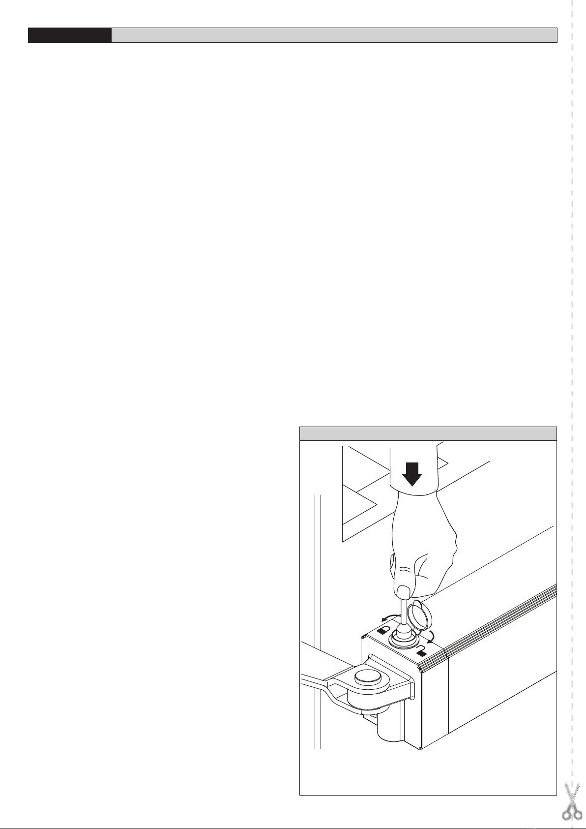
Manovra manuale :....................................................................................Chiave di sblocco
N° manovre in 24ore : ..........................................................................................60 manovre
Massima lunghezza anta : .......................................................................................1800 mm
Massimo peso anta :.................................................................................................... ~250 kg
Condizioni ambientali : ........................................................................... da -15 °C a +60 °C
Grado di protezione : ......................................................................................................... IP 44
Dimensioni :.............................................................................................................Vedere g.1
Peso operatore :.................................................................................................................. ~5kg
Lubricazione :........................................................................................grasso permanente
3.2) KIT BATTERIE KIT-BATT-BT
Tensione di carica:......................................................................................................27.2V d.c.
Corrente di carica: .......................................................................................................... 130mA
Dati rilevati alla temperatura esterna di:......................................................................25°C
Capacità batteria: .............................................................................................2x (12V 1.2Ah)
Soglia protezione batteria scarica:..........................................................................20.4Vdc
Tempo di ricarica batteria:...........................................................................................12/14 h
4) INSTALLAZIONE DELL’ATTUATORE
4.1) Veriche preliminari
Controllare:
• Chelastrutturadelcancellosiasucientementerobusta.
• Inognicaso,l’attuatoredevespingerel’antainunpuntorinforzato.
• Cheleantesimuovanomanualmenteesenzasforzopertuttalacorsa.
•
Che siano installate le battute d’arresto delle ante sia in apertura che in chiusura.
• Seilcancellononèdinuovainstallazione,controllarelostatodiusuraditutti
i componenti.
• Sistemareosostituirelepartidifettoseousurate.L’adabilitàelasicurezza
dell’automazione è direttamente inuenzata dallo stato della struttura del
cancello.
In g.2, è riportato lo schema a cui fare riferimento per l’installazione e la tabella
delle misure per il ssaggio a pilastro.
Lo schema di g.2 utilizza le seguenti convenzioni:
P staa posteriore di ssaggio al pilastro
F forcella anteriore di ssaggio dell’anta
a-b quote per determinare il punto di ssaggio della staa “P”
C valore dell’interasse di ssaggio (C = 993mm)
D lunghezza del cancello
X distanza dall’asse del cancello allo spigolo del pilastro
Z valore sempre superiore a 45 mm (b - X)
kg peso max dell’anta
α° angolo d’apertura dell’anta
4.2) Come interpretare la tabella delle misure di installazione
Dalla tabella è possibile scegliere valori di“a”e“b”in funzione dei gradi α° di aper-
tura che si desiderano ottenere. Sono evidenziati il valore di“a” e di “b”ottimale
per una apertura di α° = 90° a velocità costante.
Se si utilizzano valori di“a”e“b”troppo diversi tra loro, il movimento dell’anta non
è costante e la forza di trazione o spinta varia durante il movimento.
Per rispettare la velocità di apertura e garantire un buon funzionamento dell’ope-
ratore è opportuno che i valori“a”e “b”siano poco diversi tra loro.
Con valori max di“a” e “b”, il pistone sviluppa la massima forza.
Latabella èstataricavataper uncancellomedio dispessore 40mm.Vericare
sempre che non ci siano collisioni tra cancello ed attuatore.
4.3) Accorgimenti per installazioni particolari
Ing.3èillustrataunainstallazioneconnicchiaquandononc’èspaziosuciente

9
MANUALE PER L’INSTALLAZIONE
ITALIANO
fra anta e recinzione.
Quando la posizione dell’anta non permette di ottenere un valore di“b”presente
in tabella, in questo caso, è possibile spostare il cardine dell’anta (g.4), oppure
realizzare una nicchia nel pilastro stesso (g.5).
4.4) Ancoraggio degli attacchi al pilastro ed all’anta del cancello.
Fissare l’attacco“P” (g.6) al pilastro con una robusta saldatura.
Allostessomodosaldarealcancellolaforcella“F”facendoattenzionechel’attuatore
da montare risulti parallelo al piano di movimento del cancello g.7.
Nel caso di cancelli che si muovono in un piano inclinato (apertura verso l’interno
con vialetto in salita), il pistone consente una oscillazione rispetto all’asse oriz-
zontale dei valori massimi indicati in g.7.
• Seilpilastroèinmuratura,lapiastra“PF”dovràessereancoratainprofondità
mediante idonee zanche“Z” saldate sul retro della stessa (g.8).
• Seilpilastroèdipietraedilcancelloèpiccolo,èpossibilessarelapiastra
“PF” con quattro tasselli metallici ad espansione “T” (g.9); se il cancello non
è piccolo è consigliato usare una piastra“PF” di forma angolare (g.10).
5) BATTUTE D’ARRESTO DELLE ANTE AL SUOLO
Per il corretto funzionamento dell’attuatore,è obbligatorio utilizzare le battute di
arresto“B” sia in apertura che in chiusura come indicato in g.11
6) PREDISPOSIZIONE DELL’ IMPIANTO ELETTRICO (g.12).
Predisporre l’impianto elettrico come in g.12 facendo riferimento alle norme
vigenti per gli impianti elettrici CEI-64-8, IEC 364, armonizzazione HD384 ed
altre norme nazionali.
Tenerenettamenteseparatiicollegamentidialimentazionediretedaicollegamenti
di servizio (fotocellule, coste sensibili, dispositivi di comando ecc.).
ATTENZIONE! Per il collegamento alla rete, utilizzare cavo multipolare di
sezione minima 3x1.5mm2e del tipo previsto dalle normative vigenti. A
titolo di esempio, se il cavo è all’esterno (all’aperto), deve essere almeno
pari a H07RN-F mentre, se all’interno (in canaletta), deve essere almeno pari
a H05 VV-F con sezione 3x1.5mm2.
Realizzare i collegamenti dei dispositivi di comando e di sicurezza in armonia con
le norme per l’impiantistica precedentemente citate.
In g.12 è riportato il numero di collegamenti e la sezione per una lunghezza
dei cavi di alimentazione no a 100 metri; per lunghezze superiori, calcolare la
sezioneperilcaricorealedell’automazione.Quandolelunghezzedeicollegamenti
ausiliari superano i 50 metri o passano in zone critiche per i disturbi, è consigliato
disaccoppiare i dispositivi di comando e di sicurezza con opportuni relè.
I componenti principali per una automazione sono (g.12):
I Interruttore onnipolare omologato con apertura contatti di almeno 3mm
provvisto di protezione contro i sovraccarichi ed i cortocircuiti, atto a
sezionare l’automazione dalla rete. Se non presente, prevedere a monte
dell’automazione un interruttore dierenziale omologato di adeguata
portata e soglia da 0.03A.
Qr Quadro comando e ricevente incorporata.
SPL Scheda di preriscaldamento per funzionamento a temperature inferiori ai
10°C (opzionale).
SSelettore a chiave.
AL Lampeggiante con antenna accordata.
MOperatore
Fte Coppia fotocellule esterne (parte emittente)
Fre Coppia fotocellule esterne (parte ricevente)
Fti Coppia fotocellule interne con colonnine (parte emittente)
Fri Coppia fotocellule interne con colonnine (parte ricevente)
TTrasmittente 1-2-4 canali
RG58 Cavo per antenna
La connessione tra operatore e quadro comando viene eettuata mediante tre
cavi così identicati:
• rosso motore +
• nero motore -
• bianco controllonecorsa
In Fig. 16 è riportato lo schema di collegamento della centrale comando mod.
LOG-GK.
Nelcasosiaerratoilversodiaperturaechiusuraèpossibileinvertireleconnessioni
motore + e motore - (rosso/nero) sul quadro comando.
Il primo comando dopo un’interruzione di rete deve essere di apertura.
Le sezioni ed il numero dei li sono indicati nel disegno (g.12); per lunghezze
superiori a 100 metri, aumentare la sezione dei li. Tutte le masse metalliche dei
contenitori delle apparecchiature e degli automatismi devono essere messe a
terra.
7) REGOLAZIONE DELLA FORZA DI SPINTA
ATTENZIONE: Vericare che il valore della forza d’impatto misurato
nei punti previsti dalla norma EN12445, sia inferiore a quanto indicato
nella norma EN 12453.
La forza di spinta viene tarata mediante la regolazione di coppia presente nel
quadrocomandi.Lacoppiaottimale,devepermettereilciclocompletodiapertura
e chiusura con la minima forza necessaria. Una coppia eccessiva, può compro-
metterelasicurezzaantischiacciamento.Alcontrario,unacoppiainsuciente
può compromettere una corretta manovra. Consultare il manuale istruzioni del
quadro comandi.
8) REGOLAZIONE DEI FINECORSA
La regolazione dei ne corsa viene eettuata mediante il corretto posiziona-
mento dei magneti di ne corsa (FC1 e FC2 di Fig.1) rispetto all’asse della staa
anteriore. Allentare le viti di ssaggio dei magneti come indicato nei seguenti
paragra in modo da consentirne lo scorrimento all’interno del binario di ne
corsa“B” (Fig.1).
8.1) Regolazione ne-corsa di chiusura (Fig.13):
Portare l’anta nella posizione di chiusura desiderata, allentare le due viti A e B del
necorsa di chiusura (FC1 di Fig.1) e spostarlo in modo che la distanza tra la vite B
e l’asse della staa anteriore sia di circa 376 mm (come indicato in g. 13).
Eseguireunamanovradichiusurapervercarel’esattointerventodelnecorsa;se
l’anta si ferma in anticipo rispetto alla chiusura desiderata, spostare leggermente
il necorsa verso l’estremità dello stelo, se, invece, l’anta incontra il fermo a terra
di chiusura e l’attuatore inverte il moto, spostare leggermente il necorsa verso
il corpo dell’attuatore. Dopo aver individuato il corretto posizionamento del
necorsa, ssarlo con le due viti A e B.
8.2) Regolazione ne-corsa di apertura (Fig.14):
Portare l’anta nella posizione di apertura desiderata, allentare le due viti C e D del
necorsa di apertura (FC2 di Fig.1) e spostarlo in modo che la distanza tra la vite
D e l’asse della staa anteriore sia di circa 376 mm. (come indicato in g. 14).
Eseguire una manovra di apertura per vercare l’esatto intervento del necorsa;
sel’antasifermainanticiporispettoall’aperturadesiderata,spostareleggermente
il necorsa verso il corpo dell’attuatore, se, invece, l’anta incontra il fermo a terra
di apertura e l’attuatore inverte il moto, spostare leggermente il necorsa verso
l’estremità dello stelo. Dopo aver individuato il corretto posizionamento del
necorsa, ssarlo con le due viti C e D.
N.B. Se viene utilizzato il quadro comando LOG-GK si deve avere l’accortezza di
anticipare leggermente l’intervento dei necorsa, in quanto lo stelo, dopo aver
intercettatoinecorsa continuaamuoversipercircaaltri1-2cm.(100ms).Questo
garantisce una perfetta battuta delle ante sugli appoggi a terra.
9) APERTURA MANUALE
Ogni operatore è dotato di sblocco a chiave. Alzato il tappo copriserratura (g.15),
inserire la chiave di sblocco in dotazione e ruotare di 90° in senso orario.
Spingeremanualmentel’antaperaprireilcancello.Perripristinareilfunzionamento
motorizzato, ruotare la chiave al contrario e rimettere il tappo di copertura.
10) COPERTURE
É previsto un copristelo per proteggere lo stelo e per migliorare l’estetica dell’at-
tuatore.
Il copristelo viene montato sull’attuatore destro o sinistro semplicemente inver-
tendola posizionedel tappo dichiusura e facendoattenzione cheil forodi scarico
acqua sia rivolto verso il basso (Fig. 17).
11) VERIFICA DELL’AUTOMAZIONE
Prima di rendere denitivamente operativa l’automazione, controllare scrupo-
losamente quanto segue:
• Vericarechetuttiicomponentisianossatisaldamente.
• Controllareilcorrettofunzionamentodituttiidispositividisicurezza(foto-
cellule, costa pneumatica, ecc).
• Vericareilcomandodellamanovradiemergenza.
• Vericarel’operazionedi apertura e chiusuraconidispositivi dicomando
applicati.
• Vericarelalogicaelettronicadifunzionamentonormale(opersonalizzata)
nel quadro comandi.
12) USO DELL’AUTOMAZIONE
Poiché l’automazione può essere comandata a distanza mediante radiocoman-
do o pulsante di Start, è indispensabile controllare frequentemente la perfetta
ecienzadituttiidispositividisicurezza.
Per qualsiasi anomalia di funzionamento, intervenire rapidamente avvalendosi
di personale qualicato.

10
MANUALE PER L’INSTALLAZIONE ITALIANO
Si raccomanda di tenere i bambini a debita distanza dal raggio d’azione dell’au-
tomazione.
13) COMANDO
L’utilizzo dell’automazione consente l’apertura e la chiusura del cancello in modo
motorizzato. Il comando può essere di diverso tipo (manuale, con radiocomando,
controlloaccessiconbadgemagnetico,ecc.)secondole necessitàele caratteristi-
che dell’installazione. Per i vari sistemi di comando, vedere le relative istruzioni.
Gli utilizzatori dell’automazione devono essere istruiti al comando e all’uso.
14) MANUTENZIONE
Per qualsiasi manutenzione all’operatore, togliere alimentazione al
sistema.L’attuatore non richiede manutenzioni periodiche.
• Vericareidispositividisicurezzadelcancelloedellamotorizzazione.
• Controllareperiodicamentelaforzadispintaedeventualmentecorreggere
il valore di coppia elettrica nel quadro comandi.
• Perqualsiasianomaliadifunzionamentononrisolta,toglierealimentazione
al sistema e chiedere l’intervento di personale qualicato (installatore).
Nel periodo di fuori servizio, attivare lo sblocco manuale per consentire
l’apertura e la chiusura manuale.
15) RUMOROSITA’
Il rumore aereo prodotto dal motoriduttore in condizioni normali di utilizzo è
costante e non supera i 70dB (A).
16) DEMOLIZIONE
L’eliminazione dei materiali va fatta rispettando le norme vigenti.
Nelcasodidemolizionedell’automazionenonesistonoparticolaripericoliorischi
derivanti dall’automazione stessa.
È opportuno in caso di recupero dei materiali, che vengano separati per tipologia
(parti elettriche - rame - alluminio - plastica - ecc.).
17) SMANTELLAMENTO
Nel caso l’automazione venga smontata per essere poi rimontata in altro sito,
bisogna:
• Toglierel’alimentazioneescollegaretuttol’impiantoelettrico.
• Togliereilmotoriduttoredallabasedissaggio.
• Smontareilquadrodicomandoseseparatoetuttiicomponentidell’instal-
lazione.
• Nelcasoalcunicomponentinonpossanoessererimossiorisultinodanneggiati,
provvedere alla loro sostituzione.
18) INCONVENIENTI E RIMEDI
18.1) Funzionamento difettoso del motoriduttore.
a) Vericare con apposito strumento la presenza di tensione ai capi del motori-
duttore dopo il comando di apertura o chiusura.
b) Se il movimento dell’anta, è contrario a quello che dovrebbe essere, invertire
i collegamenti di marcia del motore (motore +rosso/ motore - nero).
c) Nel caso in cui il cancello arriva in battuta sui fermi a terra e l’attuatore inverta
il moto, signica che i necorsa non sono stati regolati correttamente. Se il
fenomeno si verica in corrispondenza del fermo di apertura, spostare il ne-
corsa di apertura verso il cardine del cancello, no ad individuare la posizione
corretta (vedi regolazione dei necorsa).
Se invece, il fenomeno si verica in corrispondenza del fermo di chiusura,
spostare il ne corsa di chiusura verso verso il tappo dello stelo, no ad indi-
viduare la posizione corretta. (vedi regolazione dei necorsa).
18.2) Funzionamento difettoso degli accessori elettrici
Tutti i dispositivi di comando e di sicurezza, in caso di guasto, possono causare
anomalie di funzionamento o blocco dell’automazione stessa.
Per individuare il guasto, è opportuno scollegare uno ad uno tutti i dispositivi
dell’automazione, no ad individuare quello che causa il difetto.
Dopo averlo riparato o sostituito, ripristinare tutti i dispositivi precedentemente
scollegati. Per tutti i dispositivi installati, fare riferimento al rispettivo manuale
istruzione.
AVVERTENZE
Ilbuonfunzionamentodell’operatoreègarantitosolosevengonorispettate
i dati riportati in questo manuale.
La ditta non risponde dei danni causati dall’inosservanze delle norme di
installazione e delle indicazioni riportate in questo manuale.
Le descrizioni e le illustrazioni del presente manuale non sono impegna-
tive.
Lasciando inalterate le caratteristiche essenziali del prodotto, la Ditta si
riservadiapportareinqualunquemomentolemodichecheessaritienecon-
venientipermiglioraretecnicamente,costruttivamenteecommercialmente
il prodotto, senza impegnarsi ad aggiornare la presente pubblicazione.

11
INSTALLATION MANUAL
ENGLISH
Thank you for buying this product, our company is sure that you will be more
than satised with the product’s performance. The product is supplied with a
“Warnings” leaet and an “Instruction booklet”. These should both be read
carefully as they provide important information about safety, installation, ope-
ration and maintenance. This product complies with the recognised technical
standards and safety regulations. We declare that this product is in conformity
with the following European Directives: 2004/108/EEC and 2006/95/EEC (and
subsequent amendments).
1) GENERAL SAFETY
WARNING! An incorrect installation or improper use of the product
can cause damage to persons, animals or things.
• The“Warnings”leaet and“Instruction booklet”supplied with this product
should be read carefully as they provide important information about safety,
installation, use and maintenance.
• Scrappackingmaterials(plastic,cardboard,polystyreneetc)accordingtothe
provisions set out by current standards. Keep nylon or polystyrene bags out
of children’s reach.
• Keeptheinstructionstogetherwiththetechnicalbrochureforfuturereference.
• Thisproductwasexclusivelydesignedandmanufacturedfortheusespecied
in the present documentation. Any other use not specied in this documen-
tation could damage the product and be dangerous.
• TheCompanydeclinesallresponsibilityforanyconsequencesresultingfrom
improper use of the product, or use which is dierent from that expected and
specied in the present documentation.
• Donotinstalltheproductinexplosiveatmosphere.
• Theconstructioncomponentsofthisproductmustcomplywiththefollowing
EuropeanDirectives:2004/108/CEE,2006/95/EEC,98/37/EECandsubsequent
amendments.Asforallnon-EEC countries,the above-mentionedstandardsas
well as the current national standards should be respected in order to achieve
a good safety level.
• TheCompanydeclinesallresponsibilityforanyconsequencesresultingfrom
failuretoobserveGoodTechnicalPracticewhenconstructingclosingstructures
(door, gates etc.), as well as from any deformation which might occur during
use.
• Theinstallationmustcomplywiththeprovisionssetout bythefollowing
EuropeanDirectives:2004/108/CEE,2006/95/EEC,98/37/EECandsubsequent
amendments.
• Disconnecttheelectricalpowersupplybeforecarryingoutanyworkonthe
installation. Also disconnect any buer batteries, if tted.
• Fitanomnipolarormagnetothermalswitchonthemainspowersupply,having
a contact opening distance equal to or greater than 3,5 mm.
• Checkthatadierentialswitchwitha0.03Athresholdisttedjustbeforethe
power supply mains.
• Checkthatearthingiscarriedoutcorrectly:connectallmetalpartsforclosure
(doors, gates etc.) and all system components provided with an earth termi-
nal.
• Fitallthesafetydevices(photocells,electricedgesetc.)whichareneeded
to protect the area from any danger caused by squashing, conveying and
shearing.
• Positionatleastoneluminoussignalindicationdevice(blinker)whereitcan
be easily seen, and x a Warning sign to the structure.
• TheCompanydeclinesallresponsibilitywithrespecttotheautomationsafety
and correct operation when other manufacturers’components are used.
• Onlyuseoriginalpartsforanymaintenanceorrepairoperation.
• Donotmodifytheautomationcomponents,unlessexplicitlyauthorisedby
the company.
• Instructtheproductuseraboutthecontrolsystemsprovidedandthemanual
opening operation in case of emergency.
• Do not allow persons or children to remain in the automation operation
area.
• Keepradiocontrolorothercontroldevicesoutofchildren’sreach,inorderto
avoid unintentional automation activation.
• Theusermustavoidanyattempttocarryoutworkorrepairontheautomation
system, and always request the assistance of qualied personnel.
• Anythingwhichisnotexpresslyprovidedforinthepresentinstructions,is
not allow
2) GENERAL OUTLINE
Electromechanicalpistondesignedtoautomaticallyoperateresidentialgates.The
irreversible gearmotor keeps the gate locked both in the closing and opening
positions, making the use of the electric lock redundant.
The actuator is supplied with an electronic torque limiter. The unit is controlled
by means of an electronic control board with torque adjustment. End-of-stroke
operation is controlled by two magnetic limiting devices.
The actuator features an obstacle detection system in compliance with EN12453
and EN 12445 Standards.
Installation must be carried out using the safety devices and controls prescribed
by the EN 12978 Standard.
The following optional accessories are available on request:
- Buer battery kit mod. KIT-BATT-BT
Allows operation of the automation even when there is no mains power supply
for a short period of time.
3) TECHNICAL SPECIFICATIONS
3.1) GEKO-S
Power supply : ................................................................................................................ 24V d.c.
Motor revolutions : .................................................................................................3800 min -1
Absorbed power :................................................................................................................40 W
Absorbed current :..............................................................................................................1.5 A
Push and pull force :.......................................................................................................2000 N
Working stroke :............................................................................................................ 280 mm
Stem speed :..................................................................................................14 mm/s approx.
Impact reaction :................................... Torque limiter aboard LOG-GK control board
End-of-stroke limitino devices: ..............................Magnetic, built-in and adjustable
Manual manoeuvre : ..............................................................................................release key
No. of manoeuvres in 24hours: .................................................................60 manoeuvres
Max. leaf length : ........................................................................................................1800 mm
Max. leaf weight :.......................................................................................................... ~250 kg
Environmental conditions:...............................................................from -15 °C to +60 °C
Protection level : ..................................................................................................................IP 44
Dimensions :...................................................................................................................See g.1
Controller weight : ............................................................................................................. ~5kg
Lubrication :................................................................................................permanent grease
3.2) BATTERY KIT KIT-BATT-BT
Charging voltage:.......................................................................................................27.2V d.c.
Charging current: ........................................................................................................... 130mA
Outside temperature when values were measured: ...............................................25°C
Battery capacity:............................................................................................... 2x (12V 1.2Ah)
Flat battery protection threshold:...........................................................................20.4Vdc
Battery charging time:.............................................................................................. 12/14 hrs
4) INSTALLATION OF THE ACTUATOR
4.1) Preliminary checks
Check that:
• Thegatestructureissucientlysturdy.
• Alsomakesurethattheactuatorpushesagainsttheleafreinforcedsection.
• Theleavesmovemanuallyandwithouteortallalongtheirstroke.
• The door stop plates are tted at the end of both closing and opening
strokes.
• Ifthegatehasnotbeenrecentlyinstalled,checkthewearconditionofall
components.
• Repairorreplacefaultyorwornparts.
The automation reliability and safety are directly inuenced by the state
of the gate structure.
The diagram in g. 2 should be used as a reference for installation and consult
the table for the distances in mounting the gate post.
The diagram in g. 2 uses the following legend:
P Gate post rear fastening bracket
F Front leaf fastening fork
a-b“P” bracket installation value
C Distance between xing points (C = 993 mm)
D Gate length
X Distance from gate axis to the edge of the post
Z Always over 45 mm (b - X)
kg max. weight of leaf
α°leaf opening in degrees
4.2) How to read the installation distance tables
Select “a”and“b” according to the angle in degrees α°that the gate has to open.
The table shows the ideal value for “a” and “b” for an opening of α°= 90° at
constant speed.
Ifthereistoolargeadierencebetween“a”and“b”,theleaf willnottravelsmoothly
and the pushing or pulling force will uctuate during its stroke.
To respect the opening speed and ensure the controller operates correctly, it is
best to keep the dierence between “a” and“b” as low as possible.
When “a” and “b” are at their maximum, the piston develops the maximum
force.
The table has been worked out for a 40 mm thick medium-size gate. Al-
ways check that there is no possible collision between the gate and the
operator.

12
INSTALLATION MANUAL ENGLISH
4.3) O-standard installations.
Fig.3showsaninstallationwitharecesswhenthereisnotsucientspacebetween
the leaf and perimeter wall.
When the leaf’s position does not allow for an “a” value listed in the table, the
leaf’s hinge pivot can be shifted (g. 4), or a recess can be made cut out of the
actual gate-post (g. 5).
4.4) Mounting the brackets to the gate-post and to the gate.
Fix the bracket“P” (g. 6) to the gate-post with a good welding.
The fork “F” should be welded in the same way to the gate taking care that the
actuator can then be mounted perfectly horizontal to the line of travel of the
gate g. 7.
If the gate operates on a slope (opening inwards with an uphill driveway), g. 7
gives the maximum oscillations of the piston with respect to its horizontal.
• Ifthegate-postisinbrick,theplate“PF”mustbesetsoundlyintothepost
using adequately sized cramps“Z” welded to the back of the plate (g. 8).
• Ifthegate-portisinstoneandthegateissmall,theplate“PF”canbemounted
with four metal expansion plugs“T”(g. 9). If a larger gate is being installed it
would be better to use a corner plate “PF”(g. 10).
5) GROUND GATE STOPS
For the controller to operate correctly the gate stop “B” must be used both in
opening and closing, as shown in g. 11.
6) THE ELECTRICAL PLANT SET-UP (g. 12).
Lay out the electrical installation (g. 16) with reference to the CEI 64-8 and IEC
364 provisions, complying with the HD 384 and other national standards in force
for electrical installation.
The mains power supply connections must be kept totally separate from the
service connections (photocells, electric edges, control devices etc.).
WARNING! For connection to the mains, use a multipolar cable with a
minimum of 3x1.5mm2cross section and complying with the previously
mentioned regulations. For example, if the cable is out side (in the open), it
has to be at least equal to H07RN-F, but if it is on the inside (or outside but
placed in a plastic cable cannel) it has to be or at least egual to H05VV-F
with section 3x1.5mm2.
Connect the control and safety devices in compliance with the previously men-
tioned electrical installation standards.
Fig.12 shows the number of connections and the cross section for power supply
cables having a length of approximately 100 metres; in case of longer cables,
calculate the cross section for the true automation load.
When the auxiliary connections exceed 50-metre lengths or go through critical
disturbance areas, it is recommended to decouple the control and safety devices
by means of suitable relays.
The main automation components are (g.12):
IType-approved omnipolar circuit breaker with at least 3mm contact ope-
ning,providedwithprotectionagainstoverloadsandshortcircuits,suitable
for cutting out automation from the mains. If not already installed, place
a type-approved dierential switch with a 0.03A threshold in the circuit
just before the automation system.
Qr Control panel and incorporated receiver.
SPL Heater board for operation at temperatures below 10°C (optional)
SKey selector
AL Blinker tuned in with antenna
MController
Fte Pair of outside photocells (transmitters)
Fre Pair of outside photocells (receivers)
Fti Pair of inside photocells with column (transmitters)
Fri Pair of inside photocells with column (receivers)
T1-2-4 channel transmitter
RG58 Antenna cable
For the connection from the controller to the control board, three cables have
been provided having the following functions:
• red motor+
• black motor-
• white end-of-strokecontrol
Fig. 16 shows the wiring diagram of the LOG-GK control unit.
Should the opening or closing direction be incorrect, it is possible to invert the
connections of motor + and motor - (red/black) on the control board.
The rst command after an interruption of the power supply should be an ope-
ning manoeuvre.
The cable sections and numbering are indicated in the diagram (g. 12).
For distances of over 100 meters, the cable section must be increased. All metal
masses in the housings of equipment and automation must be earthed.
7) ADJUSTING THE PUSHING FORCE
WARNING: Check that the impact force value measured at the points
established by the EN 12445 standard is lower than that specied in the EN
12453 standard.
The pushing force is calibrated by means of the torque regulator in the control
unit. The optimum torque must allow a complete opening or closing cycle with
the minimum force necessary. An excessive torque can reduce the anti-crush
safety.Inthe other case,an insucient torquecan impede the manoeuvres.
Consult the control unit’s instruction manual.
8) ADJUSTMENT OF THE LIMITING DEVICES
The correct adjustment of the limiting devices is obtained by positioning the
end-of-stroke magnets correctly (FC1 and FC2 in Fig.1) with respect to the axis
of the front bracket. Loosen the fastening screws of the magnets as described
in the following paragraphs so that they can slide inside the end-of-stroke track
“B” (Fig.1).
8.1) Adjustment of the closing limiting devices (Fig.13):
Move the leaf to the desired closing point, loosen the two screws A and B of the
closing limiting device (FC1 in Fig.1) and move it so that the distance between
the screw B and the axis of the front racket is 376 mm approximately (as shown
in g. 13).
Perform a closing manoeuvre to make sure that the end-of-stroke limiting device
operatescorrectly; iftheleaf stopstoofar beforethedesiredclosingpoint,slightly
move the limiting device towards the end of the stem; if, on the contrary, the leaf
hits the ground closing stopping device and the actuator reverses its moving
direction, move the end-of-stroke limiting device slightly towards the actuator
body. After identifying the correct position of the limiting device , x it using the
two screws A and B.
8.2) Adjustment of the opening limiting devices (Fig.14):
Move the leaf to the desired opening position, loosen the two screws C and D
of the opening limiting device (FC2 in Fig.1) and move it so that the distance
between the screw D and the axis of the front bracket is 376 mm approximately
(as shown in g. 14).
Perform an opening manoeuvre to make sure that the end-of-stroke limiting de-
vice operates correctly; if the leaf stops too far before the desired opening point,
slightly move the limiting device towards the actuator body; if, on the contrary,
the leaf hits the ground closing stopping device and the actuator reverses its
moving direction, move the end-of-stroke limiting device slightly towards the
end of the stem. After identifying the correct position of the limiting device , x
it using the two screws C and D.
N.B. When using the LOG-GK control board, remember to slightly anticipate
the intervention of the limiting devices because the stem, after intercepting the
limiting devices, continues to move for a further 1-2 cm. (100 ms). In this way a
perfect strike of the leaves against the ground supports is guaranteed.
9) MANUAL OPENING
Allcontrollersfeatureakey releasemechanism. Afterliftingthelock cover(g.15),
insert the release key supplied and turn it clockwise by 90°.
Push the leaf manually to open the gate. To reset the motorised operation, turn
the key in the opposite direction and ret the cover.
10) COVERS
An is available in order to protect the stem and to improve the appearance of
the actuator.
The stem cover is mounted on the right or left actuator by simply inverting the
position of the cover and making sure that the water drain outlet is directed
downwards (g. 17).
11) CHECKING THE AUTOMATION
Before considering the automation completely operational, the following checks
must be made with great care:
• Checkthatallthecomponentsarermlyanchored.
• Controlallthesafetiesworkproperly(i.e.photocells,pneumaticskirt,etc.).
• Checktheemergencymanoeuvrecontrol.
• Checktheopeningandclosingmanoeuvresusingthecontrols.
• Checkthe controlunit’selectronic logicin normal(or customised)opera-
tion.
12) USE OF THE AUTOMATION
Since the automation may be remote controlled either by radio or a Start button,
it is essential that all safeties are checked frequently.

13
INSTALLATION MANUAL
ENGLISH
Any malfunction should be corrected immediately by a qualied specialist.
Keep children at a safe distance from the eld of action of the automation.
13) THE CONTROLS
Withtheautomationthegatehasapowerdrivenopeningandclosing.Thecontrols
can come in various forms (i.e. manual, remote controlled, limited access by ma-
gneticbadge,etc.)dependingonneedsandinstallationcharacteristics.Fordetails
on the various command systems, consult the specic instruction booklets.
Anyone using the automation must be instructed in its operation and controls.
14) MAINTENANCE
When carrying out maintenance operation on the controller, disconnect it from
the mains power supply. The actuator does not require periodical maintenance
operations.
• Checkthesafetydevicesofthegateandautomation.
• Periodically check the pushing force and correct the value of the electric
torque in the control board if necessary.
• Incaseofunsolvedoperationfailures,disconnecttheunitfromthemains
power supply and ask for the intervention of qualied personnel (installer).
When the unit is out of order, activate the manual release to perform manual
opening and closing manoeuvres.
15) NOISE
The aerial noise produced by the gearmotor under normal operating conditions
is constant and does not exceed 70dB(A).
16) SCRAPPING
Materials must be disposed of in conformity with the current regulations.
In case of scrapping, the automation devices do not entail any particular risks
or danger. In case of recovered materials, these should be sorted out by type
(electrical components, copper, aluminium, plastic etc.).
17) DISMANTLING
When the automation system is disassembled to be reassembled on another
site, proceed as follows:
• Disconnectthepowersupplyandtheentireelectricalinstallation.
• Removethegearmotorfromitsxingbase.
• Disassemblethecontrolpanel,ifseparate,andallinstallationcomponents.
• Inthecasewheresomeofthecomponentscannotberemovedoraredama-
ged, they must be replaced.
18) TROUBLES AND SOLUTIONS
18.1) Incorrect operation of gearmotor
a) Check for the presence of power supply to the gearmotor using a suitable
instrument after opening or closing commands have been given.
b) If the movingdirection of the leaf is opposite tothe right one, invertthe motor
running connections (motor +red/ motor - black).
c) Should the gate stop and hit the ground stopping device and the actuator
reverse its moving direction, it means that the limiting devices have not been
adjusted correctly. If this happens on the opening stopping device, move
the opening limiting device towards the hinge of the gate until the correct
position is found(see adjustment of the limiting devices).
If, on the contrary, this happens on the closing stopping device, move the
closing limiting device towards the stem plug until the correct position is
found (see adjustment of the limiting devices).
18.2) Incorrect operation of the electrical accessories
All control and safety devices can cause, in case of failure, malfunctioning or
stoppage of the automation.
To identify the failure, it is advised to disconnect all the devices of the automation
one by one until the one causing the problem is found.
After xing or replacing the defective device, reset all the devices previously di-
sconnected. Refer to the relevant instruction manual for all the devices installed
on the automation.
WARNINGS
Correct controller operation is only ensured when the data contained in the
present manual are observed. The company is not to be held responsi-
ble for any damage resulting from failure to observe the installation
standards and the instructions contained in the present manual.
The descriptions and illustrations contained in the present manual are not
binding. The Company reserves the right to make any alterations deemed
appropriateforthetechnical,manufacturing andcommercialimprovement
of the product, while leaving the essential product features unchanged, at
any time and without undertaking to update the present publication.

14
MANUEL D’INSTALLATION FRANÇAIS
Nous vous remercions pour avoir choisi ce produit. Nous sommes certains qu’il
vousoriralesperformancesque voussouhaitez.Lisezattentivementlabrochure
“Avertissements” et le “Manuel d’instructions” qui accompagnent ce produit,
puisqu’ils fournissent d’importantes indications concernant la sécurité, l’instal-
lation, l’utilisation et l’entretien. Ce produit est conforme aux règles reconnues
de la technique et aux dispositions de sécurité. Nous certions sa conformité
avec les directives européennes suivantes: 2004/108/CEE, 2006/95/CEE (et mo-
dications successives).
1) SECURITE GENERALE
ATTENTION! Une installation erronée ou une utilisation impropre du pro-
duit peuvent provoquer des lésions aux personnes et aux animaux ou des
dommages aux choses.
• Lisezattentivementlabrochure“Avertissements” et le “Manuel d’instruc-
tions” qui accompagnent ce produit, puisqu’ils fournissent d’importantes
indications concernant la sécurité, l’installation, l’utilisation et l’entretien.
• Eliminerlesmatériauxd’emballage(plastique,carton,polystyrèneetc.)selon
les prescriptions des normes en vigueur. Ne pas laisser des enveloppes en
nylon et polystyrène à la portée des enfants.
• Conserverlesinstructionsetlesannexeràlachetechniquepourlesconsulter
à tout moment.
• Ceproduitaétéconçuetréaliséexclusivementpourl’utilisationindiquéedans
cettedocumentation.Desutilisationsnonindiquéesdanscettedocumentation
pourraient provoquer des dommages au produit et représenter une source
de danger pour l’utilisateur.
• LaSociétédéclinetouteresponsabilitédérivéed’uneutilisationimpropreou
diérente de celle à laquelle le produit a été destiné et qui est indiquée dans
cette documentation.
• Nepasinstallerleproduitdansuneatmosphèreexplosive.
• LesélémentsconstituantlamachinedoiventêtreconformesauxDirectives
Européennes suivantes: 2004/108/CEE, 2006/95/CEE, 98/37 CEE et modica-
tions successives. Pour tous les Pays en dehors du Marché Commun, outre
aux normes nationales en vigueur il est conseillé de respecter également les
normes indiquées cihaut an d’assurer un bon niveau de sécurité.
• LaSociétédéclinetouteresponsabilitéencasdenonrespectdesrèglesde
bonne technique dans la construction des fermetures (portes, portails etc.),
ainsi qu’en cas de déformations pouvant se produire pendant l’utilisation.
• L’installationdoitêtreconformeauxprescriptionsdesDirectivesEuropéennes:
2004/108/CEE, 2006/95/CEE, 98/37 CEE et modications successives.
• Couperl’alimentationélectriqueavantd’eectuern’importequelleintervention
sur l’installation. Débrancher aussi les éventuelles batteries de secours.
• Prévoirsurlaligned’alimentationdelamotorisationuninterrupteurouun
magnétothermiqueomnipolaireavecdistanced’ouverturedescontactségale
ou supérieure à 3,5 mm.
• Vérierqu’enamontdelaligned’alimentationilyauninterrupteurdiérentiel
avec seuil de 0,03A.
• Vériersil’installationdeterreesteectuéecorrectement:connectertoutes
les parties métalliques de la fermeture (portes, portails etc.) et tous les com-
posants de l’installation dotés de borne de terre.
• Appliquertouslesdispositifsdesécurité(cellulesphotoélectriques,barres
palpeuses etc.) nécessaires à protéger la zone des dangers d’écrasement,
d’entraînement, de cisaillement.
• Appliqueraumoinsundispositifdesignalisationlumineuse(feuclignotant)
en position visible, xer à la structure un panneau de Attention.
• La Société décline toute responsabilité en matière de sécurité et de bon
fonctionnement de la motorisation si des composants d’autres producteurs
sont utilisés.
• Utiliserexclusivementdespiècesoriginalespourn’importequelentretienou
réparation.
• Nepaseectuerdesmodicationsauxcomposantsdelamotorisationsinon
expressément autorisées par la Société.
• Informerl’utilisateurdel’installationsurlessystèmesdecommandeappliqués
et sur l’exécution de l’ouverture manuelle en cas d’urgence.
• Nepaspermettreàdespersonnesetàdesenfantsdestationnerdanslazone
d’action de la motorisation.
• Nepaslaisserdesradiocommandesoud’autresdispositifsdecommandeà
portée des enfants an d’éviter des actionnements involontaires de la moto-
risation.
• L’utilisateurdoitévitertoutetentatived’interventionouderéparationdela
motorisation et ne doit s’adresser qu’à du personnel qualié.
• Toutcequin’estpasexpressémentprévudanscesinstructions,estinterdit.
2) GENERALITES
Piston électromécanique conçu pour motoriser des portails de type résidentiel.
Le motoréducteur irréversible maintient le blocage en fermeture et ouverture
sans besoin d’une serrure électrique.
L’actionneur est doté d’un limiteur de couple électronique. Il doit être comman-
dé par un tableau de commande électronique doté de réglage de couple. Le
fonctionnement à la n de course est réglé par deux butées de n de course
magnétiques.
L’actionneur est doté d’un système de détection des obstacles conformément
au normatives EN12453 et EN 12445.
L’installation doit être faite en utilisant des dispositifs de sécurité et des com-
mandes conformes à la norme EN 12978.
Les accessoires en option suivants sont disponibles:
- Kit batterie de secours mod. KIT-BATT-BT
Permet le fonctionnement de la motorisation même cas de faute d’alimentation
pour une courte période.
3) CARACTERISTIQUES TECHNIQUES
3.1) GEKO-S
Alimentation :................................................................................................................. 24V d.c.
Tours du moteur : ....................................................................................................3800 min -1
Puissance absorbée :..........................................................................................................40 W
Courant absorbé :................................................................................................................1.5 A
Force de poussée et de traction :...............................................................................2000 N
Course utile :................................................................................................................... 280 mm
Vitesse de la tige :........................................................................................14 mm/s environ
Réaction au choc : ..........
Limiteur de couple intégré sur tableau de commande LOG-GK
Butées de n de course:.................................. Magnétiques incorporées et réglables
Manoeuvre manuelle :..............................................................................Clé de déblocage
N° manoeuvres en 24 heures :...................................................................60 manoeuvres
Longueur maxi du vantail :.....................................................................................1800 mm
Poids maxi du vantail :................................................................................................ ~250 kg
Conditions ambiantes : ..................................................................................-15 °C à +60 °C
Degré de protection :.........................................................................................................IP 44
Dimensions :................................................................................................................. Voir g. 1
Poids de l’opérateur :......................................................................................................... ~5kg
Lubrication :..........................................................................................graisse permanente
3.2) KIT BATTERIES KIT-BATT-BT
Tension de charge:.....................................................................................................27.2V d.c.
Courant de charge:........................................................................................................ 130mA
Données relevées à la température extérieure de:..................................................25°C
Capacité de la batterie:...................................................................................2x (12V 1.2Ah)
Seuil de protection batterie à plat: .........................................................................20.4Vdc
Temps de rechargement batterie:............................................................................12/14 h
4) INSTALLATION DU VERIN
4.1) Vérications préliminaires
Contrôler:
• Quelastructureduportailestsusammentrobuste.Entouslescas,l’action-
neur doit pousser le vantail à un endroit renforcé.
• Quelesvantauxbougentmanuellementetsanseortpourtoutesacourse.
• Quelesbutéesd’arrêtdesvantauxsontinstallées tanten ouverturequ’en
fermeture.
• Sileportailn’estpasneuf,contrôlerl’étatd’usuredetouslescomposants.
• Réparerouremplacerlespartiesdéfectueusesouusées.
La abilité et la sécurité de la motorisation sont directement inuencées par l’état
de la structure du portail.
La g. 2 illustre le schéma auquel il faut se référer pour l’installation et le tableau
des mesures pour la xation au pilier.
Le schéma de la g. 2 utilise les conventions suivantes:
P patte arrière de xation au pilier
F fourche avant de xation du vantail
a-bcotes pour déterminer le point de xation de la patte «P»
C valeur de l’entraxe de xation (C = 993mm)
D longueur du portail
X distance de l’axe du portail au bord du pilier
Z valeur toujours supérieure à 45 mm (b - X)
kg poids maxi du vantail
α°angle d’ouverture du vantail
4.2) Comment interpréter les tableaux des mesures d’installation
Il est possible de choisir sur le tableau les valeurs de «a» et de «b» en fonction des
degrés α°d’ouverture que l’on désire obtenir.
Le tableau montre la valeur de «a» et de «b» optimale pour une ouverture de α°
= 90° à une vitesse constante.
Si on utilise des valeurs de «a» et «b» trop diérentes entre elles, le mouvement
du vantail n’est pas constant et la force de traction ou de poussée varie pendant
le mouvement.
Pourrespecterla vitesse d’ouvertureetassurer le bonfonctionnement de l’opéra-
teur, il faut que les valeurs «a» et «b» ne dièrent que légèrement entre elles.Avec

15
MANUEL D’INSTALLATION
FRANÇAIS
les valeurs maxi de «a» et «b», le vérin produit la force maximale.
Letableauaété réalisépour un portailmoyende 40mmd’épaisseur.Toujours
vérier qu’il n’y a pas de collisions entre le portail et l’actionneur.
4.3) Instructions pour des installations particulières
Lag.3illustreuneinstallationavecniches’iln’yapasdeplacesusanteentre
levantailetlaclôture.
Si la position du vantail ne permet pas d’obtenir une valeur de «a» présente dans
le tableau, il est possible de déplacer le gond du portail (g. 4), ou bien de réaliser
une niche dans le pilier (g. 5).
4.4) Ancrage des xations au pilier et au vantail du portail
Bloquer la xation «P» (g. 6) au pilier au moyen d’un robuste soudage.
De la même façon, souder au portail la fourche «F» en faisant attention à ce que
le vérin à monter soit parallèle par rapport au plan de mouvement du portail
g. 7.
Dans le cas de portails qui bougent sur un plan incliné (ouverture vers l’intérieur
avecrouteencôte),levérinpermetuneoscillationparrapportàl’axehorizontal
des valeurs maximales indiquées dans la g. 7.
•
Si le pilier est en maçonnerie, la plaque «PF» devra être ancrée en profondeur avec
des agrafes spéciales «Z» soudées à l’arrière de la plaque (g. 8).
• Silepilierestenpierreetleportailestpetit,ilestpossibledexerlaplaque
«PF» avec quatre goujons métalliques «T» (g. 9); si le portail est grand, il est
conseillé d’utiliser une plaque «PF» de forme angulaire (g. 10).
5) BUTÉES D’ARRET DES VANTAUX AU SOL
Pour le bon fonctionnement de l’opérateur, il est obligatoire d’utiliser les butées
d’arrêt «B» tant en ouverture qu’en fermeture, comme indiqué dans la g. 11.
6) PRÉDISPOSITION DE L’INSTALLATION ÉLECTRIQUE (g. 12)
Prédisposer l’installation électrique (g.16) se référant aux normes en vigueur
pour les installations électriques CEI 64-8, IEC364, harmonisation HD384 et à
d’autres normes nationales.
Tenir nettement séparées les connexions d’alimentation de ligne des connexions
de service (cellules photoélectriques, barres palpeuses, dispositifs de commande
etc.).
ATTENTION! Pour la connexion à la ligne, utiliser un câble multipolaire de
section minimale 3x1.5mm2et du type prévu par les normes en vigueur. A
titre d’exemple, si le cable est à l’exterieur (exposé aux intempéries), il doit
au moins être égal à H07RN-F tandis que, si à l’interieur ou bien à l’exterieur
dans un canal de protection, il doit au moins être égal à H05 VV-F avec
3x1.5mm2de section.
Réaliser les connexions des dispositifs de commande et de sécurité selon les
normes pour les installations précédemment citées.
La g.12 montre le nombre de connexions et la section pour une longueur des
câblesd’alimentationjusqu’à100mètres;pourdeslongueurssupérieures,calculer
la section pour la charge réelle de la motorisation.
Lorsque les longueurs des connexions auxiliaires dépassent 50 mètres ou si elles
passent dans des zones critiques pour les perturbations, il est conseillé de désac-
coupler les dispositifs de commande et de sécurité avec des relais adéquats.
Les composants principaux d’une automation sont (g.12):
IInterrupteur omnipolaire homologué avec ouverture des contacts d’au
moins3mm, dotéde protectioncontrelessurchargeset les courts-circuits,
en mesure de couper la motorisation de la ligne. En cas d’absence, prévoir
en amont de la motorisation un interrupteur diérentiel homologué de
portée adéquate avec seuil de 0.03A.
Qr Tableau de commande et récepteur incorporé.
SPL Carte de préchauage pour fonctionnement à des températuresinférieu-
res à 10°C (en option).
SSélecteur à clé.
AL Feu clignotant avec antenne accordée
MOpérateur
Fte Couple de cellules photoélectriques extérieures(partie émettrice)
Fre Couple de cellules photoélectriques extérieures (partie réceptrice)
Fti CoupledecellulesphotoélectriquesintérieuresaveccolonnettesCF(partie
émettrice)
Fri CoupledecellulesphotoélectriquesintérieuresaveccolonnettesCF(partie
réceptrice)
TEmetteur 1-2-4 canaux
RG58 Câble avec antenne
La connexion entre opérateur et tableau de commande est eectuée par trois
câbles identiés comme suit:
• rouge moteur+
• noir moteur-
• blanc contrôlebutéedendecourse
La Fig. 16 illustra le schéma de connexion de l’unité de commande mod. LOG-
GK.
Siladirectiond’ouvertureetdefermeturen’estpasexacte,ilestpossibled’inverser
les connexions moteur + et moteur - (rouge/noir) sur le tableau de commande.
La première commande après une coupure d’alimentation doit être d’ouver-
ture.
Les sections et le nombre des ls sont indiqués dans le plan (g. 12); pour des
longueurs supérieures à 100 m. augmenter la section des ls. Toutes les masses
métalliques des boîtiers des appareillages et des automatismes doivent être
mis à la terre.
7) RÉGLAGE DE LA FORCE DE POUSSÉE
ATTENTION: Vérier que la valeur de la force d’impact mesurée aux
endroits prévus par la normeEN 12445, est inférieure aux indications
de la norme EN 12453.
Laforcedepousséeserègleenréglantlecoupleprésentdanslacentrale.Lecouple
optimal doit permettre le cycle complet d’ouverture et de fermeture avec la force
minimale nécessaire. Un couple trop haut peut compromettre la sécurité antié-
crasement.Parcontre,uncoupleinsusantpeutcompromettreunemanoeuvre
correcte. Consulter le manuel d’instructions de la centrale de commande.
8) REGLAGE BUTEES DE FIN DE COURSE
Le réglage des butées de n de corse est eectuée en positionnant correctement
les aimants de n de course (FC1 et FC2 Fig. 1) par rapport à l’axe de la patte
avant. Desserrer les vis de xation des aimants comme indiqué aux paragraphes
suivants, de telle façon à permettre le coulissement à l’intérieur du rail de n de
course“B” (Fig. 1).
8.1) Réglage de la butée de n de course de fermeture (Fig. 13):
Porter le vantail dans la position de fermeture voulue, desserrer les deux vis A
et B de la butées de n de course de fermeture (FC1 de Fig. 1) et la déplacer de
telle façon que la distance entre la vis B et l’axe de la patte avant est d’environ
376 mm (comme indiqué à la g. 13).
Eectuer une manoeuvre de fermeture pour vérier si l’intervention de la butée
dendecourseestexacte;silevantails’arrêtetroptôtparrapportàlafermeture
voulue, déplacer légèrement la butée de n de course vers l’extrémité de la tige,
si, pas contre, le vantail cogne contre la butée au sol de fermeture et l’actionneur
inverselemouvement,déplacerlégèrementlabutéedende courseverslecorps
de l’actionneur. Après avoir établi le positionnement correct de la butée de n
de course, la xer avec les deux vis A et B.
8.2) Réglage de la butée de n de course d’ouverture (Fig. 14):
Porter le vantail dans la position d’ouverture voulue, desserrer les deux vis C et
D de la n de corse d’ouverture (FC2 de Fig. 1) et la déplacer de telle façon que
la distance entre la vis D et l’axe de la patte avant est d’environ 376 mm. (comme
indiqué à la g. 14).
Eectuer une manoeuvre d’ouverture pour vérier si l’intervention de la butée
dendecourseestexacte;silevantails’arrêtetroptôtparrapportàl’ouverture
voulue,déplacerlégèrementlabutéedendecourseverslecorpsdel’actionneur,
si, pas contre, le vantail cogne contre la butée au sol d’ouverture et l’actionneur
inverse le mouvement, déplacer légèrement la butée de n de course vers l’ex-
trémité de la tige. Après avoir établi le positionnement correct de la butée de n
de course, la xer avec les deux vis C et D.
N.B. Si on utilise le tableau de commande LOG-GK, il faut avoir soin d’anticiper
légèrement l’intervention des butées de n de course, puisque la tige, après avoir
occulté les butées de n de course, continue à bouger encore pour 1-2 cm. (100
ms). Ceci assure une butée parfaite des vantaux sur les appuis au sol.
9) OUVERTURE MANUELLE
Chaque opérateur est doté de déblocage à clé. Après avoir soulevé le couvercle
de la serrure (g. 14), enfoncer la clé de déblocage fournie en dotation et tourner
de 90° dans le sens des aiguilles d’une montre.
Pousser le vantail manuellement pour ouvrir le portail. Pour rétablir le fonction-
nement motorisé, tourner la clé dans le sens contraire et remettre le couvercle
à sa place.
10) COUVERTURES
Un couvre-tige est prévu, pour protéger la tige et améliorer l’esthétique de
l’actionneur.
Lecouvre-tigesemontesurl’actionneurdroitougauchesimplementeninversant
lapositiondubouchondefermetureetens’assurantqueletroudedéchargement
est orienté vers le bas (Fig. 17).
11) VÉRIFICATION DE L’AUTOMATION
Avantdemettredénitivementenoeuvrel’automation,contrôlersoigneusement

16
MANUEL D’INSTALLATION FRANÇAIS
ce qui suit:
• S’assurerquetouslescomposantssontsolidementxés.
• Contrôlerlebonfonctionnementdetouslesdispositifsdesécurité(cellules
photoélectriques, barre palpeuse pneumatique etc.).
• Vérierlacommandedelamanoeuvred’urgence.
• Vérierl’opérationd’ouvertureetdefermetureaveclesdispositifsdecom-
mande appliqués.
• Vérierlalogiqueélectroniquenormale(oupersonnalisée)defonctionnement
de la centrale de commande.
12) UTILISATION DE L’AUTOMATION
L’automationpouvantêtrecommandéeàdistanceparradiocommandeoubouton
deStart,ilestindispensabledecontrôlersouventlebonfonctionnementdetous
les dispositifs de sécurité.
Pour toute anomalie de fonctionnement, intervenir rapidement en s’adressant
à du personnel qualié.
Il est recommandé de tenir les enfants loin du rayon d’action de l’automation.
13) COMMANDE
L’utilisation de l’automation permet l’ouverture et la fermeture du portail de
façon motorisée. La commande peut être de type diérent (manuelle, avec ra-
diocommande,contrôledesaccèsaveccartemagnétiqueetc.)selonlesbesoins
et les caractéristiques de l’installation. Pour les diérents types de commande,
voir les instructions correspondantes. Les utilisateurs de l’automation doivent
être informés sur la commande et l’utilisation.
14) ENTRETIEN
Avant d’eectuer n’importe quel entretien sur l’opérateur, couper l’alimentation
au système. L’actionneur n’exige aucun entretien périodique.
• Vérierlesdispositifsdesécuritéduportailetdelamotorisation.
• Contrôlerpériodiquementlaforcedepousséeetéventuellementcorrigerla
valeur de couple électrique dans le tableau des commandes.
• Pour n’importe quelle anomalie de fonctionnement non résolue, couper
l’alimentation au système et demander l’intervention d’un personnel qualié
(installateur).
Pendant la période de hors service, activer le déblocage manuel pour permettre
l’ouverture et la fermeture manuelle.
15) BRUIT
Le bruit aérien produit par le motoréducteur dans des conditions d’utilisation
normales est constant et ne dépasse pas 70dB(A).
16) DÉMOLITION
L’éliminationdes matériauxdoit êtrefaite enrespectantlesnormes envigueur.En
casde démolitiondela motorisation,il n’existeaucundanger ourisque particulier
dérivant de la motorisation.
Encas de récupérationdesmatériaux, ilsera opportundeles trier selonleur genre
(parties électriques - cuivre - aluminium - plastique - etc.).
17) DÉMANTÉLEMENT
Si la motorisation doit être démontée et remontée ailleurs, il faut:
• Couperl’alimentationetdébranchertoutel’installationélectrique.
• Enleverlemotoréducteurdesabasedexation.
• Démonterl’unitédecommandesiséparéeettouslescomposantsdel’instal-
lation.
• Sidescomposantsnepeuventpasêtreenlevésousontendommagés,ilfaudra
les remplacer.
18) INCONVENIENTS ET SOLUTIONS
18.1) Fonctionnement défectueux du motoréducteur
a) Vérier avec un instrument spécial la présence de tension aux extrémités du
motoréducteur après la commande d’ouverture ou fermeture.
b) Si le mouvement du vantail est au contraire, il faut inverser les connexions de
marche du moteur (moteur + rouge/moteur – noir).
c) Si le portail arrive en butée sur les arrêts au sol et l’actionneur inverse le
mouvement, cela signie que les butées de n de course n’ont pas été réglées
correctement. Si cela se produit au niveau de la butée d’ouverture, déplacer la
n de course d’ouverture vers les gonds du portail jusqu’à localiser la position
correcte (voir réglage des butées de n de course).
Si par contre cela se produit au niveau de la butée de fermeture, déplacer la butée
de n de course vers le bouchon de la tige, jusqu’à localiser la position correcte
(voir réglage des butées de n de course).
18.2) Fonctionnement défectueux des accessoires électriques
Tous les dispositifs de commande et de sécurité, en cas de panne, peuvent pro-
voquer des anomalies de fonctionnement ou le blocage de la motorisation.
Pour localiser la panne, il convient de débrancher un à la fois les dispositifs de la
motorisation jusqu’à localiser celui qui provoque la panne.
Après l’avoir réparé ou remplacé, reconnecter tous les dispositifs précédemment
débranchés. Pour tous les dispositifs installés, se référer au manuel d’instructions
correspondant.
AVERTISSEMENTS
Le bon fonctionnement de l’actionneur n’est assuré que si les données
fournies dans ce manuel sont respectées. Le constructeur ne répond pas
pour les dommages provoqués par le non respect des normes d’installation
et des indications fournies dans ce manuel.
Les descriptions et les gures de ce manuel n’engagent pas le constructeur.
En laissant inaltérées les caractéristiques essentielles du produit, la Société
se réserve le droit d’apporter à n’importe quel moment les modications
qu’elle juge opportunes pour améliorer le produit du point de vue tech-
nique, commercial et de construction, sans s’engager à mettre à jour cette
publication.

17
MONTAGEANLEITUNG
DEUTSCH
Wir danken Ihnen, daß Sie sich für diese Anlage entschieden haben. Ganz sicher
wird sie mit ihren Leistungen Ihren Ansprüchen vollauf gerecht werden. Lesen
Sie aufmerksam die Broschüre “Hinweisen“ und die “Gebrauchsanweisung“
durch,diedem Produktbeiliegen.Sie enthaltenwichtige HinweisezurSicherheit,
Installation, Bedienung und Wartung der Anlage. Dieses Produkt genügt den
anerkanntentechnischenRegelnundSicherheitsbestimmungen.Wirbestätigen,
daß es mit folgenden Europäischen Richtlinien übereinstimmt: 2004/108/EWG,
2006/95/EWG (und ihren nachfolgende Änderungen).
1) ALLGEMEINE SICHERHEITSHINWEISE
VORSICHT!MontagefehleroderderunsachgemäßeGebrauchdesProduktes
können zu Personen- oder Sachschäden führen.
• LesenSieaufmerksamdieBroschüremitden“Hinweisen”und die“Gebrau-
chsanweisung”, die dem Produkt beiliegen. Sie enthalten wichtige Hinweise
zur Sicherheit, Montage, Bedienung und Wartung der Anlage.
• Verpackungsmaterialien(Kunststo,Karton,Polystyrolu.a.)sindnachden
einschlägigen Vorschriften zu entsorgen. Keine Nylon- oder Polystyroltüten
in Reichweite von Kindern liegenlassen.
• DieAnleitungistfürzukünftigeEinsichtnahmealsBeilagezurtechnischen
Akte aufzubewahren.
• DiesesProduktwurdeausschließlichfürdenGebrauchentwickeltundgebaut,
so wie er in dieser Dokumentation beschrieben wird. Davon abweichende
Verwendungen können Schadens- und Gefahrenquellen darstellen.
• DerHerstellerlehntjedeVerantwortungfürFolgenab,diedurchdenunsach-
gemäßen oder nicht bestimmungsgemäßen, weil in dieser Dokumentation
nicht genannten Gebrauch entstehen.
• DieAnlagedarfnichtinexplosionsgefährdeterAtmosphäreinstalliertwer-
den.
• DieBauteilederMaschinemüssendenfolgendenEuropäischenRichtlinien
entsprechen: 2004/108/EWG, 2006/95/EWG, 98/37EWG und nachfolgende
Änderungen. Für alle Länder außerhalb der EWG gilt: Neben den geltenden
Landesvorschriftensollten aus Sicherheitsgründen auch die oben genannten
Bestimmungen beachtet werden.
• DerHerstellerlehntjedeVerantwortungfürFolgenab,diedurchnichtfach-
gerechte Ausführungen von Schließvorrichtungen (Türen, Tore usw.), oder
durch Verformungen während des Betriebes entstehen.
• DieMontagemußimEinklangmitfolgendenEuropäischenRichtlinienerfolgen:
2004/108/EWG, 2006/95/EWG, 98/37EWG und nachfolgende Änderungen.
• VorjedemEingrianderAnlagedieStromversorgungunterbrechen.Auch
Puerbatterien abklemmen, falls vorhanden.
• Versehen Sie dieVersorgungsleitung der Anlage mit einem Schalter oder
allpoligen magnetthermischen Schutzschalter mit einem Kontaktabstand
von mindestens 3,5 mm.
• DerVersorgungsleitungmußeinFehlerstromschutzschaltermiteinerSchwelle
von 0.03A vorgeschaltet sein.
• Prüfen Sie den Erdungsanschluß: Alle Metallteile der Schließvorrichtung
(Türen, Tore usw.) und alle Anlagenkomponenten mit Erdungsklemme an-
schließen.
• AlleSicherheitsvorrichtungen (Lichtschranken,Sicherheitsleisten u. a.)an-
bringen, die verhindern, daß sich im Torbereich jemand quetscht, schneidet
oder mitgerissen wird.
• MindestenseineLeuchtsignaleinrichtung(Blinklicht)angutsichtbarerStelle
anbringen. Befestigen Sie ein Warnschild am Torgestell.
• DerHerstellerlehntjedeVerantwortungfürdieSicherheitunddieFunktion-
stüchtigkeit der Anlage ab, wenn Komponenten anderer Produzenten ver-
wendet werden.
• FürWartungenundReparaturenausschließlichOriginalteileverwenden.
• KeineUmbautenanAnlagenkomponentenvornehmen,wennsienichtau-
sdrücklich vom Hersteller genehmigt wurden.
• WeisenSiedenAnlagennutzerindievorhandenenSteuerungssystemeund
die manuelle Torönung im Notfall ein.
• KindernoderErwachsenenistesnichtgestattet,imAktionsbereichderAnlage
zu verweilen.
• KeineFernbedienungenoderandereSteuerungsvorrichtungeninReichweite
von Kindern liegenlassen. Sie könnten die Anlage versehentlich in Gang
setzen.
• DerBetreiberhatjedenVersucheinesEingriesoderderReparaturzuunter-
lassen. Nur entsprechend qualizierte Fachleute sind hierzu befugt.
• Alles,wasnichtausdrücklichindieserAnleitunggenanntist,istuntersagt.
2) ALLGEMEINES
Elektromechanischer Spindelantrieb für Tore mit geringer Önungsfrequenz.
Der selbsthemmende Spindelantrieb hält die Blockierung im geschlossenen und
geöneten Zustand aufrecht. Einsetzbar fürTore bis 1,80 m Flügellänge und 250
kg max. Torgewicht.
DerAntriebistmiteinemelektronischenDrehmoment-BegrenzerausgestattetDie
AnsteuerungerfolgtüberdieSteuerungLOG-GK,dieübereineDrehomenteinstel-
lung verfügt. Die Endabschaltung wird über zwei Magnetendschalter geregelt.
Der Antrieb ist mit einem System zur Erfassung von Hindernissen versehen und
entspricht damit den Normen EN12453 und EN 12445.
Die Installation muß mit Sicherheits- und Steuerungsvorrichtungen vorgenom-
men werden, die der Norm EN 12978 entsprechen.
Folgendes Sonderzubehör ist erhältlich:
- Kit Puerbatterie Mod. KIT-BATT-BT
Es gestattet das Betreiben der Anlage auch bei kurzzeitigem Stromausfall.
3) TECHNISCHE DATEN
3.1) GEKO-S
Versorgungsspannung: ............................................................................................. 24V d.c.
Motordrehzahl: ......................................................................................................3800 min -1
Leistungsaufnahme : .........................................................................................................40 W
Stromaufnahme : ................................................................................................................1.5 A
Bewegungsübertragung: ...........................................................................Schub und Zug
Schub- und Zugkraft: ................................................................................................... 2000 N
Nutzhub :........................................................................................................................ 280 mm
Schaftgeschwindigkeit: ..................................................................................14 mm/s circa
Stoßreaktion:........... Drehmomentbegrenzer, in die Steuerung LOG-GK integriert
Endschalter:............................................ Eingebaute, einstellbare Magnetendschalter
Handbedienung : ........................................................................... Entriegelungsschlüssel
Betriebsvorgänge in 24 Stunden: ..................................................................60 Vorgänge
Max. Flügellänge: ......................................................................................................1800 mm
Max. Flügelgewicht: .................................................................................................... ~250 kg
Umgebungsbedingungen: ..................................................................... -15 °C bis +60 °C
Schutzgrad: .......................................................................................................................... IP 44
Abmessungen: ...................................................................................................... Siehe Fig. 1
Gewicht der Antriebsanlage: ........................................................................................ ~5kg
Schmierung : .................................................................................................... Permanentfett
3.2) KIT BATTERIEN KIT-BATT-BT
Ladespannung: ............................................................................................................27.2Vd.c.
Ladestrom: ....................................................................................................................... 130mA
Meßdaten bei einer Außentemperatur von: ............................................................ 25°C
Batteriekapazität: ............................................................................................2x (12V 1.2Ah)
Schutzschwelle Batterieentladung: ..................................................................... 20.4Vd.c.
Auadedauer Batterie: ...............................................................................................12 - 14 h
4) INSTALLIERUNG DES ANTRIEBES
4.1) Vorabkontrollen
Überprüfen Sie folgende Punkte:
• DasTorgestellmusssolidegenugsein.
• Auf jeden Fall muss derTorügel am Befestigungspunkt desTorantriebes
verstärkt werden.
• DieTorügelmüssensich über diegesamteStreckehinwegmühelosvon
Hand bewegen lassen.
• Toranschlägefür“Toroen”und“Torgeschlossen”werdenempfohlen.
• WenndasTorälterenDatumsist,müssenalleKomponentenaufihrenVer-
schleißzustand untersucht werden.
• DefekteoderverschlisseneTeilesindzureparierenoderzuersetzen.Zuver-
lässigkeit und Sicherheit der Anlage hängen unmittelbar vom Zustand des
Torgestelles ab.
In Fig. 2 ist das Schema für die Installation, sowie die Maßtabelle für die Befesti-
gung am Pfeiler dargestellt.
Das Schema der Fig. 2 benutzt folgende Bezeichnungen:
P Pfostenansch zur Befestigung am Pfeiler
F Toransch zur Befestigung am Tor
a-b Maße zur Bestimmung des Befestigungspunktes des Bügels P
C Wert des Abstandes der Befestigungen P und F (C = 993 mm)
D Torlänge
X Entfernung der Torachse von der Pfeilerkante
Z Wert immer oberhalb von 45 mm (b - X)
kg Maximales Flügelgewicht
α° Önungswinkel des Flügels
4.2) Erläuterung der Tabelle Fig. 2
Aus der Tabelle kann man Werte “a” und “b” in Abhängigkeit des gewünschten
Önungswinkels α°wählen. In der Tabelle ist der optimale Wert der Maße“a”und
“b”für eine Önung bei gleichbleibender Geschwindigkeit bei einemWinkel von
α°= 90 ° hervorgehoben.
Wenn man Werte von“a” und “b” benutzt, die sich untereinander zu sehr unter-
scheiden, ist die Flügelgeschwindigkeit nicht gleichbleibend und die Zugbzw.
Schubkraft ändert sich während der Bewegung.
Um die Önungsgeschwindigkeit einzuhalten und einen störungsfreien Betrieb
des Antriebes zu gewährleisten, ist es anzuraten, die Werte “a” und “b” unterei-
nander nicht zu sehr abweichen zu lassen.

18
MONTAGEANLEITUNG DEUTSCH
Mit den Höchstwerten von “a” und “b” entwickelt der Kolben seine maximale
Kraft.
DieTabellebeziehtsichaufeinnormalesTormiteinerDickevon40mm.Prüfen
Sie stets, ob Kollisionsstellen zwischen Tor und Antrieb vorhanden sind.
4.3) Installation bei geringen Platz
In Fig.3wird eineInstallationmitWandvertiefungdargestellt,dies ist erforderlich,
wenn kein ausreichender Platz zwischen Flügeltor und Mauer besteht.
Wenn die Flügeltorstellung nicht den Erhalt eines in der Tabelle vorhandenen
Wertes “a” erlaubt, ist es möglich, den Angelzapfen des Flügeltores zu versetzen
(Fig. 4), oder eine Nische im Pfeiler anzubringen. (Fig. 5).
4.4) Befestigung des Tor- und Pfostenansches:
Den Pfostenansch“P”(Fig. 6) an den Pfeiler festschweißen.
Den Toransch“F” an das Tor anschweißen und dabei darauf achten, daß der zu
montierende Antrieb vollkommen waagerecht zum Bewegungslauf des Tores
(Fig. 7) angebracht wird.
Bei Toren, die sich auf einer geneigten Fläche bewegen (steigendes Tor bei Ö-
nung) gestattet der Kolben eine Neigung zur waagrechten Achse mit den in Fig.
7 angegebenen Werten.
• WennderPfeilerauseinerMauerbesteht,mußdiePlatte“PF”mittelsgeeigneter
Krampen“Z”, welcheauf der Plattenrückseiteangeschweißtwerden,befestigt
werden. (Fig. 8).
• WennderPfeilerausSteinunddasTorkleinist,kannmandiePlatte“PF”mitvier
Metallspreizdübeln “T” befestigen (Fig. 9). Wenn das Tor größer ist, empehlt
sich die Benutzung einer Winkelplatte “PF” (Fig. 10).
5) BODENANSCHLÄGE
Für einen störungsfreien Betrieb des Antriebes ist es empfohlen, die Anschläge
“B” sowohl bei Önung als auch bei Schließung wie in Fig. 11 dargesellt, zu
benutzen.
6) VORBEREITUNG DER ELEKTRISCHEN ANLAGE (Fig. 12).
Bereiten Sie die elektrische Anlage (Fig.16) nach den einschlägigen Vorschriften
für elektrische Anlagen CEI 64-8, IEC364, Harmonisierung HD384 und anderen
landesspezischen Normen vor.
Die Netzversorgungsanschlüsse von den Niederspannungsanschlüssen (Licht-,
schranke, Sicherheitsleisten, Steuerungsvorrichtungen u. a.) klar getrennt hal-
ten.
VORSICHT! Für den Anschluss an das Stromnetz ein mehrpoliges Kabel mit
Mindestquerschnitt 3x1.5mm2benutzen, dessen Typ von den geltenden
Vorschriften zugelassen ist. Wenn das Kabel beispielsweise außen (im
Freien) liegt, muss es mindestens H07RN-F entsprechen, liegt es innen
(im Kabelkanal), muss es mindestens H05 VV-F entsprechen und einen
Querschnitt von 3x1.5mm2haben.
Die Steuerungs- und Sicherheitsvorrichtungen müssen im Einklang mit den
vorstehend zitierten Anlagenormen angeschlossen werden.
In Fig.12 ist die Anzahl der Anschlüsse und der Querschnitt für eine Kabellänge
bis 100 Meter aufgeführt. Für längere Kabel ist der Querschnitt anhand der An-
lagenreallast zu berechnen.
Wenn die Hilfsanschlüsse mehr als 50 Meter lang sind oder kritische Störung-
sbereiche durchlaufen, sollten die Steuerungs- und Sicherungsvorrichtungen
mit geeigneten Relais entkoppelt werden.
Die Hauptbestandteile einer automatisierten Anlage (Fig.12):
I Allpoliger geprüfter Schalter mit Kontaktabstand von mindestens 3mm,
versehen mit einer Einrichtung, welche die Anlage als Schutz gegen
Überlasten und Kurzschlüssen vom Netz trennen kann. Falls noch nicht
vorhanden, muss der Anlage ein geprüfter Fehlerstromschutzschalter
mit ausreichender Festigkeit und einer Schwelle von 0.03A vorgeschaltet
werden.
Qr Steuerung mit eingebautem Funkempfänger
SPL Vorheizkarte für einen Betrieb bei Temperaturen unter 10 °C (Zubehör).
S Schlüsselschalter.
AL Blinklicht mit passender Stabantenne
M Antrieb
Fte Externes Lichtschrankenpaar (Sender)
Fre Externes Lichtschrankenpaar (Empfänger)
Fti nternes Lichtschrankenpaar mit Ständer (Sender)
Fri Internes Lichtschrankenpaar mit Ständer (Empfänger)
T Handsender mit 1-2-4 Kanäle
RG58 Antennenkabel
Die Verbindung zwischen Antrieb und Steuerung erfolgt durch drei gekenn-
zeichnete Kabel:
•rotMotor+
•schwarzMotor-
•weißEndschalterkontrolle
In Fig. 16 ist der Anschlußplan der Steuerung LOG-GK dargestellt.
Bei falscher Drehrichtung (nach stromlosen Zustand muß der erste Impuls
das Tor önen) müssen die Anschlüsse Motor + und Motor - (rot/schwarz) auf
der Steuerung getauscht werden.
Die Querschnitte und die Anzahl der Drähte sind in der Zeichnung (Fig. 12) dar-
gestellt. Für Längen über 100 Meter den Querschnitt der Drähte erhöhen. Alle
metallischen Massen müssen geerdet sein.
7) EINSTELLUNG DER SCHUBKRAFT
ACHTUNG:Überprüfen,daßderWertderAufschlagkraft,derandenvon
der Norm EN 12445 vorgesehenen Stellen gemessen wurde, niedriger
als der in der Bestimmung EN 12453 angegebene ist.
Die Schubkraft wird mittels der Drehmomenteinstellung der Steuerung LOG-GK
vorgenommen.DasoptimaleDrehmomentmußdenvollständigenÖnungs-und
Schließzyklus mit der minimal notwendigen Kraft erlauben. Ein zu hohes Dreh-
momentkanndieAntiquetschsicherheitbeeinträchtigen.Imentgegengesetzten
Fall kann ein zu geringes Drehmoment einen reibungslosen Bewegungszyklus
beeinträchtigen.
Hinweise in der Montageanleitung der Steuerung LOG-GK beachten.
8) EINSTELLUNG DER ENDSCHALTER
Die Endschalter werden eingestellt, indem man die richtige Position der Ma-
gnetschalter (FC1 und FC2 in Fig. 1) entlang des Kolbens ermittelt. Lockern Sie
die Feststellschrauben der Magneten, wie es in den folgenden Abschnitten
beschrieben wird. Die Magneten lassen sich dann im Innern der Schiene bewe-
gen. (Fig.1).
8.1) Einstellung des Schließungs-Endschalters (Fig.13):
Bringen Sie den Flügel in die gewünschte Schließstellung, dann die beiden
Schrauben A und B des Schließungsendschalters (FC1 Fig.1) lockern und den
Schalterso verschieben,daßder AbstandzwischenderSchraubeBundder Achse
des Toransches etwa 376 mm beträgt (siehe auch Fig. 13).
PrüfenSieanhandeinesTestvorganges,obderEndschalterrichtiganspricht.Bleibt
der Flügel vorzeitig stehen, versetzen Sie den Endschalter leicht zum Schaftende
hin. Läuft der Flügel hingegen soweit, daß er auf den Halteanschlag im Boden
trit und kehrt der Antrieb daraufhin die Bewegungsrichtung um, so versetzen
Sie den Endschalter etwas zum Antriebskörper hin. Wenn die korrekte Position
gefunden ist, den Endschalter mit den beiden Schrauben A und B xieren.
8.2) Einstellung des Önungs-Endschalters (Fig.14):
BringenSiedenFlügelindiegewünschteÖnungsstellung,lockernSiediebeiden
Schrauben C und D des Önungs-Endschalters (FC2 in Fig.1) und verschieben
Sie den Schalter so weit, bis die Distanz zwischen der Schraube D und der Achse
des Torügels etwa 376 mm beträgt (siehe auch Fig. 14).
PrüfenSieanhandeinesTestvorganges,obderEndschalterrichtiganspricht.Bleibt
derFlügelvorzeitigstehen,versetzenSiedenEndschalterleichtzumAntriebskörper
hin. Läuft der Flügel hingegen soweit, daß er auf den Halteanschlag im Boden
trit und kehrt der Antrieb daraufhin die Bewegungsrichtung um, so versetzen
Sieden Endschalter etwas zum Schaftende.Wenndie korrektePositiongefunden
ist, den Endschalter mit den beiden Schrauben C und D xieren.
ZurBeachtung:WirddieSteuerung LOG-GKmit derKonguration“Aufrechterhal-
tung Sperre on” verwendet, den Ansprechzeitpunkt der Endschalter leicht
vorziehen, denn der Flügel bewegt sich, nachdem er den Endschalter betätigt
hat, noch etwa 1-2 cm weiter (100 ms). Dadurch ist gewährleistet, daß die Flügel
genau an die Bodenanschläge anlegen.
9) MANUELLE ÖFFNUNG
Der GEKO-S ist mit einem Entriegelungsmechanismus ausgestattet.
ZunächstdieSchloßabdeckkappe(Fig.15)abnehmen,dannmitdembeiliegenden
Entriegelungsschlüssel im Uhrzeigersinn um 90° drehen.
Zur Önung des Tores, wird der Flügel von Hand aufgeschoben. Um den Motor-
betrieb wieder aufzunehmen, drehen Sie den Schlüssel in die Gegenrichtung
und setzen den Verschlußstopfen wieder auf.
10) ABDECKUNGEN
Es wird vorther eine Schaftabdeckung gesehen, die den Schaft schützt und die
Optik des Antriebes verbessert.
Die Schaftabdeckung wird auf den rechts- oder linksseitigen Antrieb montiert,
indem man einfach nur die Position der Verschlußkappe vertauscht und darauf
achtet, daß die Wasserablaßönung nach unten zeigt (Fig. 17).
11) KONTROLLE DES ANTRIEBES
Bevor man den Antrieb endgültig in Betrieb nimmt, gewissenhaft folgendes
überprüfen:

19
MONTAGEANLEITUNG
DEUTSCH
• Überprüfen,oballeBestandteilesolidebefestigtsind.
• Das richtige Funktionieren aller Sicherheitsvorrichtungen kontrollieren
(Lichtschranke, Sicherheitsleiste usw.)
• DieSteuerungdesNotfallvorgangesüberprüfen.
• DieÖnungs-undSchließungsvorgängemitdenangebrachtenSteuerung-
svorrichtungen prüfen.
• DieelektronischeLogikdesNormalbetriebes(oderdespersonalisierten)auf
der Steuerung überprüfen.
12) GEBRAUCH DES ANTRIEBES
WeilderAntriebmittelsFernbedienungaufDistanzoderdurcheinenStarterknopf
gesteuert werden kann, ist es unvermeidbar, häug die vollständige Einsatzfähi-
gkeit aller Sicherheitsvorrichtungen kontrollieren.
Bei jeder Betriebsstörung schnell einschreiten und Fachpersonal hinuziehen.
Es wird empfohlen, Kinder in gebührender Entfernung vom Aktionsradius der
Anlage zu halten.
13) STEUERUNG
Der Gebrauch der Automation erlaubt die motorisierte Önung und Schließung
des Tores. Die Steuerung kann unterschiedlich sein (manuell, mit Fernbedie-
nung, Zugangskontrolle mit Magnetkarte usw.) je nach Notwendigkeiten und
Merkmalen der Anlage. Für die unterschiedlichen Steuerungssysteme siehe die
dazugehörigen Anweisungen.
Die Benutzer der Automation müssen mit der Steuerung und der Benutzung der
Anlage vertraut gemacht werden.
14 ) WARTUNG
Vor jeder Wartungstätigkeit an der Antriebsanlage ist die Stromversorgung zu
unterbrechen. Der Antrieb bedarf keiner regelmäßigen Wartung.
• PrüfenSiedieSicherheitseinrichtungendesToresunddesAntriebes.
• KontrollierenSieinbestimmtenZeitabständendieSchubkraft.BeiAbweichun-
gen ist der Wert des elektrischen Drehmomentes in der Steuerung LOG-GK
zu korrigieren.
• BeijedernichtbehobenenFehlfunktionistdieStromversorgungdesSystems
zu unterbrechen. Rufen Sie einen Fachmann hinzu (Installateur).
Während die Anlage außer Betrieb ist, aktivieren Sie die Entriegelung, damit
sich das Tor manuell önen und schließen läßt.
15) GERÄUSCHENTWICKLUNG
Das vom Getriebemotor erzeugte Luftgeräusch ist unter normalen Betriebsbe-
dingungen gleichbleibend und überschreitet nicht den Wert von 70dB(A).
16) VERSCHROTTUNG
Die Materialien sind unter Beachtung der einschlägigen Vorschriften zu entsor-
gen.
Bei der Verschrottung gehen von der Anlage keine besonderen Gefahren oder
Risiken aus.
Werden die Materialien wiederverwertet, sollten sie nach Arten getrennt werden
(elektrische Komponenten - Kupfer - Aluminium - Kunststo usw).
17) DEMONTAGE
Wird die Anlage abgebaut, um sie an einem anderen Ort erneut zu installieren,
ist folgendes zu beachten:
• StromversorgungunterbrechenunddiegesamteelektrischeAnlageabklem-
men.
• DenAntriebvondenBefestigungennehmen.
• DieSteuerungundalleAnlagenbauteiledemontieren.
• Teile,dienichtentferntwerdenkönnenoderbeschädigtsind,müssenersetzt
werden.
18) STÖRUNGEN UND ABHILFE
18.1) Fehlfunktionen des Getriebemotors.
a) PrüfenSiemiteinemgeeignetenMeßgerät,obnachErteilungeinesÖnungs-
oder Schließbefehles an den Endkontakten des Getriebemotors Spannung
anliegt.
b) Wenn der Flügel sich entgegengesetzt zur vorgesehenen Richtung bewegt,
vertauschen Sie die Betriebsanschlüsse des Motors (Motor + rot / Motor -
schwarz). (Nach stromlos muß der Antrieb önen).
c) Trit das Tor beim Anlegen auf die Endanschläge am Boden und kehrt der
Antrieb daraufhin die Bewegungsrichtung um, sind die Endschalter nicht
richtigjustiert.Tritt diesamÖnungs-Anschlagauf,versetzenSie denentspre-
chenden Endschalter hin zur Torangel, bis die richtige Position gefunden ist
(siehe Einstellung der Endschalter).
Ist dies hingegen am Schließungs-Anschag zu beobachten, so versetzen Sie
den entsprechenden Endschalter in Richtung Schaftende, bis die richtige Lage
gefunden ist (siehe Einstellung der Endschalter).
18.2) Fehlfunktionen des elektrischen Zubehörs
Alle Steuer- und Sicherheitsvorrichtungen können im Falle eines Defektes
Betriebsstörungen oder sogar den Ausfall der automatischen Antriebsanlage
verursachen.
Umden Defektzulokalisieren,istzuempfehlen,sämtliche Steuerungsanschlüsse
der Reihe abzuklemmen, bis die Ursache des Defektes gefunden ist.
Nachdem das defekte Teil instandgesetzt oder ausgetauscht wurde, müssen
alle bislang abgeklemmten Vorrichtungen wieder in Betriebsbereitschaft ge-
nommen werden. Die Vorgehensweise ersehen Sie bitte aus dem jeweiligen
Betriebshandbuch.
HINWEISE
Der einwandfreie Betrieb des Antriebes ist nur dann garantiert, wenn die
AngabenausdiesemHandbuchbeachtetwerden.DerHerstellerhaftetnicht
für Schäden, die durch Mißachtung der Installationsanweisungen und der
Angaben aus diesem Handbuch entstehen.
DieBeschreibungenundbildlichenDarstellungenindiesemHandbuchsind
unverbindlich.DerHerstellerbehältsich-ohneauchzurAktualisierungdieser
Unterlagen verpichtet zu sein - jederzeit vor, Änderungen vorzunehmen,
wenn er diese als technische oder bauliche Verbesserungen für notwendig
erachtet und die wesentlichen
Produkteigenschaften unverändert bleiben.

20
MANUAL DE INSTALACIÓN ESPAÑOL
Al agradecerle la preferencia que ha manifestado por este producto, la empresa
está segura de que de él obtendrá las prestaciones necesarias para sus exigen-
cias. Lea atentamente el folleto“Advertencias” y el “Manual de instrucciones”
que acompañan a este producto, pues proporcionan importantes indicaciones
referentes a la seguridad, la instalación, el uso y el mantenimiento del mismo.
Este producto cumple los requisitos establecidos por las normas reconocidas
de la técnica y las disposiciones relativas a la seguridad. Conrmamos su con-
formidad con las siguientes directivas europeas: 2004/108/CEE, 2006/95/CEE (y
modicaciones sucesivas).
1) SEGURIDAD GENERAL
¡ATENCION! Una instalación equivocada o un uso impropio del producto
puede crear daños a personas, animales o cosas.
Es preciso:
• Leeratentamenteelfolleto“Advertencias” y el “Manual de instrucciones”
que acompañan a este producto, pues proporcionan importantes indicacio-
nes referentes a la seguridad, la instalación, el uso y el mantenimiento del
mismo.
• Eliminarlosmaterialesdeembalaje(plástico,cartón,poliestireno,etc.)según
lo previsto por las normas vigentes. No dejar bolsas de nylon o poliestireno
al alcance de los niños.
• Conservarlasinstruccionesparaadjuntarlasalfolletotécnicoyparaconsultas
futuras.
• Este producto ha sido proyectado y construido exclusivamente para la
utilización indicada en esta documentación. Usos no indicados en esta do-
cumentación podrían causar daños al producto y ser fuente de peligro.
• LaEmpresadeclinatodaresponsabilidadquederivedelusoimpropiodel
producto o de un uso distinto de aquél para el que está destinado y que
aparece indicado en la presente documentación.
• Noinstalarelproductoenatmósferaexplosiva.
• Loselementosconstructivosdelamáquinadebenserconformesalassiguientes
DirectivasEuropeas:2004/108/CEE,2006/95/CEE,98/37/CEEymodicaciones
sucesivas. Para todos los Países extra CEE, además de las normas nacionales
vigentes, para asegurar un buen nivel de seguridad, es conveniente respetar
también las normas citadas antes.
• LaEmpresadeclinatodaresponsabilidadquederivedelainobservanciadela
BuenaTécnicaenlaconstruccióndeloselementosdecierre(puertas,cancelas,
etc.), así como de las deformaciones que se podrían vericar durante el uso.
• LainstalacióndebeserconformealoprevistoporlassiguientesDirectivasEu-
ropeas: 2004/108/CEE, 2006/95/CEE, 98/37/CEE y modicaciones sucesivas.
• Cortarelsuministrodecorrienteantesdeefectuarcualquierintervenciónen
la instalación. Desconectar también eventuales baterías tampón, si las hay.
• Prever,enlareddealimentacióndelautomatismo,uninterruptorounma-
gnetotérmico omnipolar con una distancia de abertura de los contactos igual
o superior a 3,5 mm.
• Vericarque,antesdelareddealimentación,hayauninterruptordiferencial
con un umbral de 0,03A.
• Vericarsilatomadetierrahasidorealizadacorrectamente:conectartodas
laspartesmetálicasde cierre(puertas,cancelas,etc.)y todoslos componentes
de la instalación provistos de borne de tierra.
• Aplicartodoslosdispositivosdeseguridad(fotocélulas,barrassensibles,etc.)
necesarios para proteger el área del peligro de aplastamiento, transporte o
cizallado.
• Aplicaralmenosundispositivodeseñalizaciónluminosa(luzintermitente)
en posición visible y jar a la estructura un cartel de Atención.
• La Empresa declina toda responsabilidad, a efectos de la seguridad y del
buen funcionamiento del automatismo, si se emplean componentes de otros
fabricantes.
• Usar exclusivamente partes originales al realizar cualquier operación de
mantenimiento o reparación.
• Nomodicarningúncomponentedelautomatismosiantesnosehasido
expresamente autorizado por la Empresa.
• Instruir alusuario del equipo sobrelos sistemasde mando aplicadosy la
ejecución de la apertura manual en caso de emergencia.
• No permitir que personas o niños estacionen en el campo de acción del
automatismo.
• Nodejarradiomandosuotrosdispositivosdemandoalalcancedelosniños,
para evitar el accionamiento involuntario del automatismo.
• Elusuario debe:evitarcualquier intentodeintervención oreparacióndel
automatismoydirigirseúnicamenteapersonalcualicado.
• Todoloquenoestáexpresamenteprevistoenestasinstruccionesnoestá
permitido.
2) DATOS GENERALES
Pistón electromecánico proyectado para automatizar cancelas de tipo residen-
cial. El motorreductor, irreversible, mantiene el bloqueo de cierre y apertura sin
necesidad de electrocerradura.
El servomotor está provisto de limitador de par electrónico y debe ser gobernado
por un cuadro de mandos electrónico dotado de regulación de par. El funciona-
miento de n de carrera está regulado por dos nes de carrera magnéticos.
El servomotor está provisto de un sistema de detección de obstáculos, de con-
formidad con las normas EN12453 y EN 12445.
La instalación debe realizarse utilizando dispositivos de seguridad y mandos
conformes a la EN 12978.
Están disponibles los siguientes accesorios opcionales:
- Kit batería tampón mod. KIT-BATT-BT
Permite el funcionamiento del automatismo en caso de que falte, por un breve
período, el suministro de corriente.
3) DATOS TECNICOS
3.1) GEKO-S
Alimentación:..................................................................................................................24 V d.c.
Revoluciones motor: ..............................................................................................3800 min -1
Potencia absorbida :...........................................................................................................40 W
Corriente absorbida :..........................................................................................................1,5 A
Fuerza de empuje y tracción:......................................................................................2000 N
Carreraútil: ..................................................................................................................... 280 mm
Velocidad vástago:.........................................................................................14 mm/s aprox.
Reacción al impacto: ...........
Limitador de par integrado en el cuadro de mandos LOG-GK
Fines de carrera:.............................................. Magnéticos, incorporados y regulables
Maniobra manual:............................................................................... Llave de desbloqueo
N° maniobras en 24 horas:..............................................................................60 maniobras
Longitud máxima hoja:............................................................................................1800 mm
Peso máximo hoja:....................................................................................................... ~250 kg
Condiciones ambientales:......................................................................De -15 °C a +60 °C
Grado de protección:......................................................................................................... IP 44
Dimensiones: .......................................................................................................Véase la g. 1
Peso operador: ................................................................................................................... ~5 kg
Lubricación: Grasa permanente
3.2) KIT BATERIAS KIT-BATT-BT
Tensión de carga:.......................................................................................................27,2 V d.c.
Corriente de carga:........................................................................................................ 130 mA
Datos registrados a la temperatura exterior de:........................................................25°C
Capacidad batería:........................................................................................ 2 x (12 V 1,2 Ah)
Umbral de protección batería agotada:.............................................................20,4 V c.c.
Tiempo de recarga batería:.........................................................................................12/14 h
4) INSTALACION DEL SERVOMOTOR
4.1) Controles preliminares
Es preciso controlar:
• Quelaestructuradelacancelaseasucientementerobusta.
• Encualquiercaso,elservomotordebeempujarlahojaenunpuntoreforza-
do.
• Quelashojassemuevanmanualmenteysinesfuerzoportodalacarrera.
• Quesehayaninstaladolostopesdelashojastantodeaperturacomode
cierre.
• Silacancelanoesnueva,setienequecontrolarelestadodedesgastede
todos los componentes.
• Hayquearreglarosustituirlaspartesdefectuosasodesgastadas.
La abilidad y la seguridad del automatismo están directamente inuidas por
el estado de la estructura de la cancela.
En la g. 2 se observa el esquema que hay que tener en cuenta para la instalación
y la tabla de las medidas para la jación al pilar.
En este esquema se utilizan las siguientes convenciones:
P abrazadera posterior de jación al pilar
F horquilla anterior de jación de la hoja
a-bcotas para determinar el punto de jación de la abrazadera“P”
C valor de la distancia entre ejes de jación (C = 993 mm)
D longitud de la cancela
X distancia desde el eje de la cancela hasta la arista del pilar
Z valor siempre superior a 45 mm (b - X)
kg peso máx. de la hoja
α° ángulo de apertura de la hoja
4.2) Cómo interpretar la tabla de las medidas de instalación
De la tabla se pueden escoger valores de“a”y“b”en función de los grados α°de
apertura que se deseen obtener. Se evidencia el valor de“a”y de“b”óptimo para
una apertura de α°= 90° a velocidad constante.
Si se utilizan valores de “a” y “b” demasiado diferentes entre sí, el movimiento
de la hoja no es constante y la fuerza de tracción o empuje varía durante el
movimiento.
Para respetar la velocidad de apertura y garantizar un buen funcionamiento del
operador, es conveniente que los valores “a”y“b” sean poco diferentes entre sí.
Con valores máx. de“a” y “b”, el pistón desarrolla la máxima fuerza.
Table of contents
Languages:
Other O&O Gate Opener manuals
Popular Gate Opener manuals by other brands

Nice
Nice DBM5 Instructions and warnings for the fitter

DITEC
DITEC OBBI3BH-E2H quick reference

DKS
DKS 1601 Installation & owner's manual

IQ Gate Systems
IQ Gate Systems IntelliSlide IQ-5000-S Installation and instruction manual

GFA
GFA 10004055 10004 installation instructions

Mighty Mule
Mighty Mule FM350 installation manual