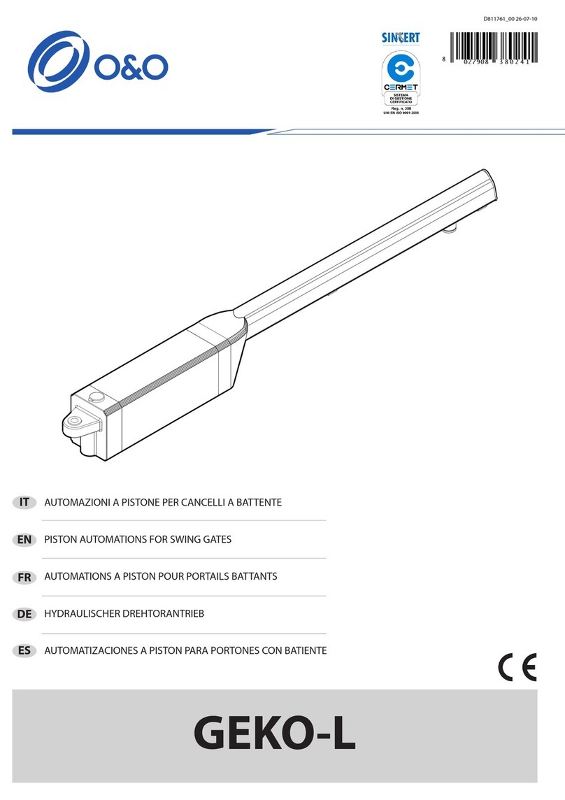
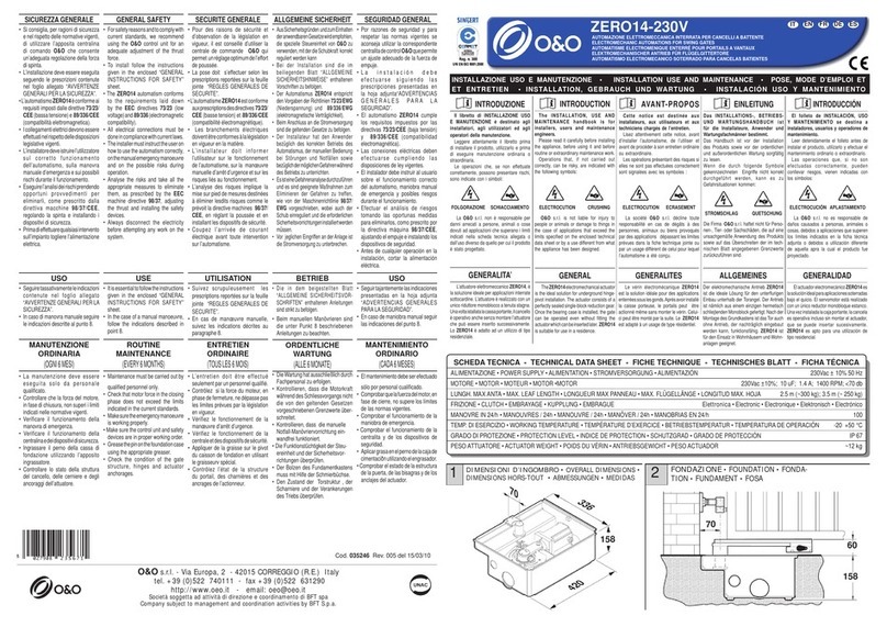
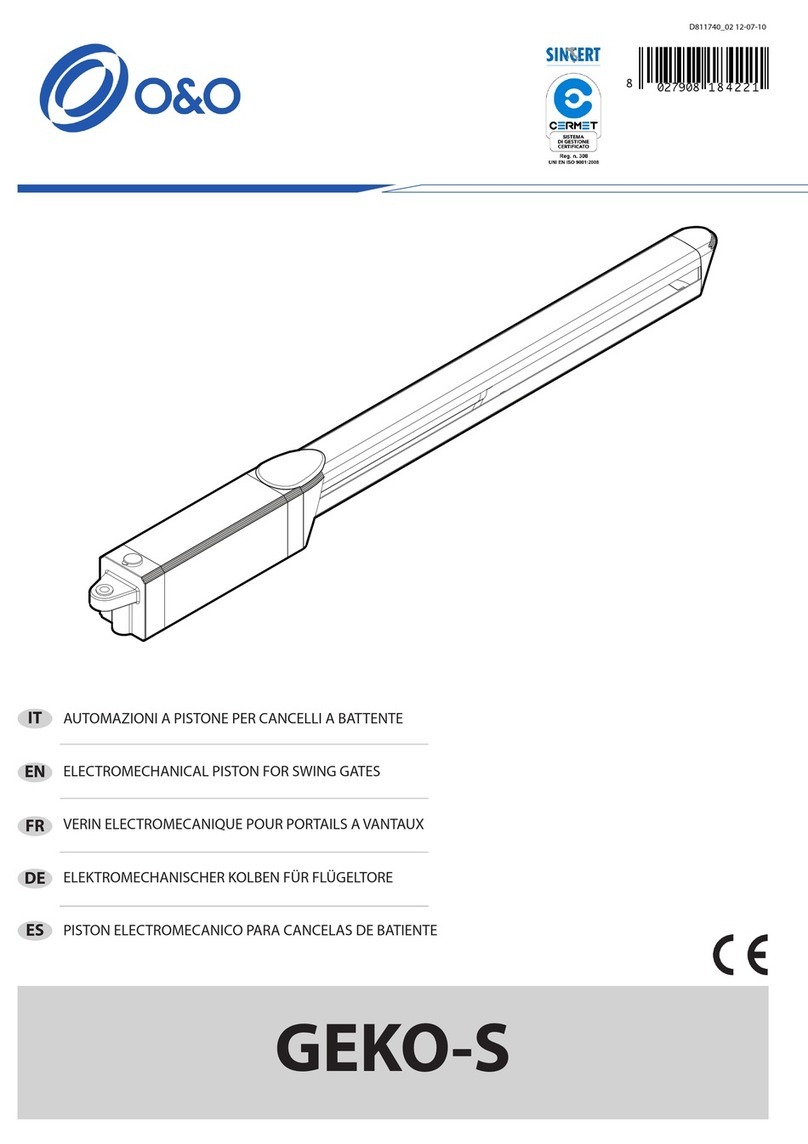
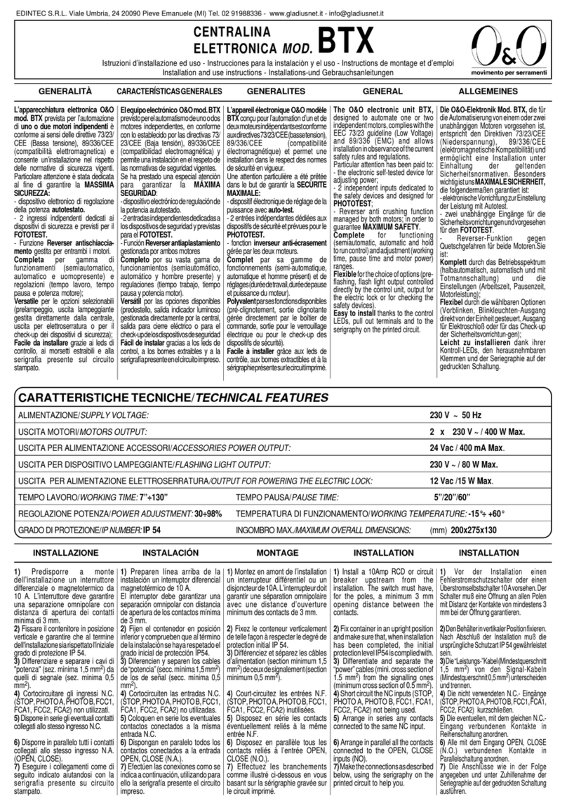
O&O ZERO14-24V Quick start guide

AUTOMAZIONE ELETTROMECCANICA INTERRATA PER CANCELLI A BATTENTE
ELECTROMECHANIC AUTOMATIONS FOR SWING GATES
AUTOMATISME ELECTROMENIQUE ENTERRÉ POUR PORTAILS A VANTAUX
ELEKTROMECHANISCHER ANTRIEB FÜR FLÜGELGITTERTORE
AUTOMATISMO ELECTROMECANICO SOTERRADO PARA CANCELAS BATIENTES
ZERO14-24V
INSTALLAZIONE USO E MANUTENZIONE • INSTALLATION USE AND MAINTENANCE • POSE, MODE D’EMPLOI ET
ET ENTRETIEN • INSTALLATION, GEBRAUCH UND WARTUNG • INSTALACIÓN USO Y MANTENIMIENTO
INTRODUZIONE
Il libretto di INSTALLAZIONE USO
E MANUTENZIONE è destinato agli
installatori, agli utilizzatori ed agli
operatori della manutenzione.
Leggere attentamente il libretto
prima di installare il prodotto, utilizzarlo
e prima di eseguire manutenzione
ordinaria o straordinaria.
Le operazioni che, se non effettuate
correttamente, possono presentare
rischi, sono indicate con i simboli:
INTRODUCTION
The INSTALLATION, USE AND
MAINTENANCE handbook is for
installers, users and maintenance
engineers.
Please read it carefully before
installing the appliance, before using
it and before routine or extraordinary
maintenance work.
Operations that, if not carried out
correctly, can be risky, are indicated
with the following symbols:
AVANT-PROPOS
Cette notice est destinée aux
installateurs, aux utilisateurs et aux
techniciens chargés de l’entretien.
Lisez attentivement cette notice,
avant d’installer l’automatisme, de
l’utiliser et avant de procéder à son
entretien ordinaire ou extraordinaire.
Les opérations présentant des
risques si elles ne sont pas effectuées
correctement sont signalées avec les
symboles :
INTRODUCCIÓN
El folleto de INSTALACIÓN, USO
Y MANTENIMIENTO se destina a
instaladores, usuarios y operadores
de mantenimiento.
Leer detenidamente el folleto antes
de instalar el producto, utilizarlo y
efectuar el mantenimiento ordinario o
extraordinario.
Las operaciones que, si no son
efectuadas correctamente, pueden
conllevar riesgos, vienen indicadas con
los símbolos:
FOLGORAZIONE SCHIACCIAMENTO
La O&O s.r.l. non è responsabile
per danni arrecati a persone, animali
o cose dovuti ad applicazioni che
superano i limiti indicati nella scheda
tecnica allegata o dall’uso diverso
da quello per cui il prodotto è stato
progettato.
GENERALITA’
L’attuatore elettromeccanico ZERO14-
24V,èlasoluzioneidealeperapplicazioni
interrate sottocardine. L’attuatore è
realizzato con un unico riduttore
monoblocco a tenuta stagna. Una volta
istallata la cassa portante, il cancello
è operativo anche senza montare
l’attuatore che può essere inserito
successivamente. Lo ZERO14-24V è
adatto ad un utilizzo di tipo residenziale.
ELECTROCUTION CRUSHING
O&O s.r.l. is not liable for injury
to people or animals or damage to
things in the case of applications that
exceed the limits specified on the
enclosed technical data sheet or by a
use different from what the appliance
has been designed.
GENERAL
TheZERO14-24Velectromechanical
actuator is the ideal solution for
underground hinge-pivot installation.
Theactuatorconsistsofaperfectlysealed
single-block reduction gear. Once the
bearingcase isinstalled, thegate canbe
operatedevenwithoutfittingthe actuator
which can be inserted later.
ZERO14-24V is suitable for use in a
residence.
ELECTROCUTION ECRASEMENT
La société O&O s.r.l. décline toute
responsabilité en cas de dégâts à
des personnes, animaux ou biens
provoqués par des applications
dépassant les limites prévues dans
la fiche technique jointe ou par un
usage différent de celui pour lequel
l’automatisme a été conçu.
GENERALITES
Levérin électromécaniqueZERO14-
24V est la solution idéale pour des
applications enterrées sous les gonds.
Aprésavoirinstallélacaisseporteuse,le
portails peut être actionné même sans
monter le vérin. Celui-ci peut être monté
parla suite.Le ZERO14-24V est adapté
à un usage de type résidentiel.
EINLEITUNG
Das INSTALLATIONS-, BETRIEBS-
UND WARTUNGSHANDBUCH ist
für die Installateure, Anwender und
Wartungsfachmänner bestimmt.
Das Handbuch ist vor der Installation
des Produkts sowie vor der
ordentlichen und außerordentlichen
Wartung sorgfältig zu lesen.
Wenn die durch folgende Symbole
gekennzeichneten Eingriffe nicht
korrekt durchgeführt werden, kann es
zu Gefahrsituationen kommen:
STROMSCHLAG QUETSCHUNG
Die Firma O&O s.r.l. haftet nicht für
Personen-, Tier- oder Sachschäden, die
aufeine unsachgemäßeAnwendungdes
Produkts sowie auf das Überschreiten
der im technischen Blatt angegebenen
Grenzwerte zurückzuführen sind.
ALLGEMEINES
Der elektromechanische Antrieb
ZERO14-24V ist die ideale Lösung für
den unterflurigen Einbau unterhalb der
Torangel. Der Antrieb ist nämlich aus
einemeinzigen hermetischschlieβenden
Monoblock gefertigt. Nach der Montage
des Grundkastens ist das Tor auch ohne
Antrieb, der nachträglich eingebaut wer-
den kann, funktionsfähig. ZERO14-24V
ist für den Einsatz in Wohnhäusern und
Wohnanlagen geeignet.
ELECTROCUCIÓN APLASTAMIENTO
La O&O s.r.l. no es responsable de
daños causados a personas, animales
o cosas, debidos a aplicaciones que
superen los límites indicados en la ficha
técnica adjunta o debidos a utilización
diferente de aquella apra la cual el
producto fue proyectado.
GENERALIDAD
ElactuadorelectromecánicoZERO14-
24V eslasolución idealparaaplicaciones
soterradas bajo el quicio. El servomotor
està realizado con un único reductor
monobloque estanco. Una vez instalada
la caja portante, la cancela es operativa
incluso sin montar el actuador, que se
puede insertar sucesivamente. ZERO14-
24V es apto para una utilización de tipo
residencial.
SCHEDA TECNICA - TECHNICAL DATA SHEET - FICHE TECHNIQUE - TECHNISCHES BLATT - FICHA TÉCNICA
ALIMENTAZIONE • POWER SUPPLY •ALIMENTATION • STROMVERSORGUNG •ALIMENTAZIÓN 230Vac ± 10% 50 Hz
MOTORE • MOTOR • MOTEUR • MOTOR •MOTOR 24Vdc; 10.1 A; 2100 RPM
LUNGH. MAX ANTA• MAX. LEAF LENGTH • LONGUEUR MAX PANNEAU •MAX. FLÜGELLÄNGE •LONGITUD MAX. HOJA 2.5 m (~400 kg); 3.5 m (~ 250 kg)
FRIZIONE • CLUTCH • EMBRAYAGE • KUPPLUNG • EMBRAGUE Elettronica • Electronic • Electronique • Elektronisch • Electrónico
MANOVRE IN 24/h • MANOUVRES / 24h • MANOUVRE / 24h • MANÖVER / 24h • MANOBRIAS EN 24/h 100
TEMP. DI ESERCIZIO • WORKING TEMPERATURE •TEMPÉRATURE D’EXERCICE • BETRIEBSTEMPERATUR • TEMPERATURADE OPERACIÓN -20 +50 °C
GRADO DI PROTEZIONE • PROTECTION LEVEL • INDICE DE PROTECTION • SCHUTZGRAD • GRADO DE PROTECCIÓN IP 67
PESOATTUATORE •ACTUATOR WEIGHT • POIDS DU VÉRIN •ANTRIEBSGEWICHT • PESOACTUADOR ~10 kg
DIMENSIONI D’INGOMBRO • OVERALL DIMENSIONS
DIMENSIONS HORS-TOUT • ABMESSUNGEN • MEDIDAS
1
420
158
336
70
2FONDAZIONE • FOUNDATION • FONDATION
FUNDAMENT • FOSA
60
70
158
IT FR ESDEEN

1
) Ligne monophasée 2 x 1,5 + T
2) Tableau des boutons 4 x 0,5
3) Sélecteur à clé 3 x 0,5
4) Moteur 1 2 x 1,5
5) Moteur 2 2 x 2,5
6) Fin de course 3 x 1
7) Photocellule émettrice 2 x 0,5
8) Photocellule réceptrice 4 x 0,5
9) Verrouillage électrique 2 x 0,5
10) Clignotant 2 x 0,5
11) Antenne (câb. blindé) RG58
11) Récepteur 4 x 0,5
1) Línea monofásica 2 x 1,5 + T
2) Caja de pulsadores 4 x 0,5
3) Selector de llave 3 x 0,5
4) Motor 1 2 x 1,5
5) Motor 2 2 x 2,5
6) Fin de carrera 3 x 1
7) Fotocélula transmisor 2 x 0,5
8) Fotocélula receptor 4 x 0,5
9) Cierre electrónico 2 x 0,5
10) Indicador intermitente 2 x 0,5
11) Antena (c. blindado) RG58
11) Receptor 4 x 0,5
1) Single-phase line 2 x 1,5 + E
2) Push button panel 4 x 0,5
3) Key switch 3 x 0,5
4) Motor 1 2 x 1,5
5) Motor 2 2 x 2,5
6) Switch sensors 3 x 1
7) Trasmitting photocell 2 x 0,5
8) Receiving photocell 4 x 0,5
9) Electric lock 2 x 0,5
10) Flasher 2 x 0,5
11) Antenna (with shielding) RG58
11) Receiver use 4 x 0,5
1) Linea Monofase 2 x 1,5 + T
2) Pulsantiera 4 x 0,5
3) Selettore a chiave 3 x 0,5
4) Motore 1 2 x 1,5
5) Motore 2 2 x 2,5
6) Sensori finecorsa 3 x 1
7) Fotocell. trasmett. 2 x 0,5
8) Fotocell. ricevitore 4 x 0,5
9) Elettroserratura 2 x 0,5
10) Lampeggiante 2 x 0,5
11) Antenna (cavo scherm.) RG58
11) Utilizzo ricevente 4 x 0,5
1) Einphasenleitung 2 x 1,5 + E
2) Tastatur 4 x 0,5
3) Schlüsselschalter 3 x 0,5
4) Motor 1 2 x 1,5
5) Motor 2 2 x 2,5
6) Endlagensensoren 3 x 1
7) Senderfotozelle 2 x 0,5
8) Empfängerfotozelle 4 x 0,5
9) Elektro-Schloß 2 x 0,5
10) Blinkleuchte 2 x 0,5
11) Antenne (m.Abschirm.) RG58
11) Empfänger 4 x 0,5
NOTA CAVI • CABE NOTE •CONNEXION CABLES • BEMERKUNG ZU DEN KABEL ANSCHLÜSSEN • NOTA CABLES
3
LOG-GK
4DISPOSIZIONE MOTORIDUTTORE • GEARMOTOR LAYOUT • DISPOSITION DU MOTORÉDUCTEUR
DISPOSITION DES GETRIEBEMOTORS • DISPOSICIÓN DEL MOTORREDUCTOR
120°
A
A
A
Finecorsa
Limit switch
AFin de course
Schranksperre
final de carrera
DX SX
120°

5ASSEMBLAGGIO FINECORSA • ASSEMBLY OF END-OF-STROKE • ASSEMBLAGE DE LA FIN DE COURSE •
ZUSAMMEMBAU DES ENDANSCHLAGES • ENSAMBLAJE DEL FIN DE CARRERA
6MONTAGGIO MOTORIDUTTORE
GEARMOTOR FITTING
MONTAGE DU MOTORÉDUCTEUR
MONTAGE DES GETRIEBEMOTORS
MONTAJE DEL MOTORREDUCTOR
CH19
7MONTAGGIO LEVE • ASSEMBLY LEVERS
MONTAGE DES LEVIERS • MONTAGE DES HEBEL
MONTAJE DE LAS PALANCAS
COLLEGAMENTI ELETTRICI • ELECTRICAL CONNECTIONS • BRANCHEMENTS ELECTRIQUES •
ELEKTRISCHE ANSCHLÜSSE • CONEXIONES ELÉCTRICAS
8
• Consultare il manuale d’installazione e uso della centralina LOG-GK
• Consult the LOG-GK control unit’s installation and operating manual
•Consulterlemanueld’installationetd’utilisationdelacentraleLOG-GK
•
Die Installations und Bedienungsanleitungen der Steuereinheit
LOG-GK nachschlagen.
• Consultar el manual de instalación y uso de la centralita LOG-GK
SX
DX
+ BROWN
- BLUE
KEY-L 014

9REGOLAZIONE FINECORSA • END-OF-STROKE ADJUSTMENT • RÉGLAGE FIN DE COURSE
EINSTELLEN DER ENDLAGENSENSOREN • REGULACION DE LOS FINES DE CARRERA
Fca
Fca
Fcc
Fcc
DX SX
Cancello chiuso DX
Gate closed DX
Portail fermee DX
Geschlossen Gittertür DX
Cancela cerrada DX
Cancello aperto DX
Open gate DX
Portail ouvert DX
Geöffnete Gittertür DX
Cancela abierta DX
Fca = Finecorsa di apertura • Opening limit switch • Fin de course d’ouverture • Öffnungsendschalter • final de carrera de abertura
Fcc = Finecorsa di chiusura • Closing limit switch • Fin de course de fermeture • Schließendschalter • Final de carrera de cierre

MANOVRA MANUALE • MANUAL MANOEUVRE • MANOEUVRE MANUELLE • MANUELLES MANÖVRIEREN • MANIOBRA MANUAL
10
120°
Cancello chiuso SX
Gate closed SX
Portail fermee SX
Geschlossen Gittertür SX
Cancela cerrada SX
Cancello aperto SX
Open gate SX
Portail ouvert SX
Geöffnete Gittertür SX
Cancela abierta SX

SICUREZZA GENERALE
• Si consiglia, per ragioni di sicurezza
e nel rispetto delle normative vigenti,
di utilizzare l’apposita centralina
di comando O&O che consente
un’adeguata regolazione della forza
di spinta.
• L’installazione deve essere eseguita
seguendo le prescrizioni contenute
nel foglio allegato “AVVERTENZE
GENERALI PER LA SICUREZZA”.
•L’automatismoZERO14èconformeai
requisiti imposti dalle direttive 73/23/
CEE(bassatensione)e 89/336/CEE
(compatibilità elettromagnetica).
• Icollegamentielettricidevonoessere
effettuatinelrispettodelledisposizioni
legislative vigenti.
• Utilizzare sempre cavi previsti dalle
normative vigenti
• L’installatoredeveistruirel’utilizzatore
sul corretto funzionamento
dell’automatismo, sulla manovra
manuale d’emergenza e sui possibili
rischi durante il funzionamento.
• Eseguirel’analisideirischiprendendo
opportuni provvedimenti per
eliminarli, come prescritto dalla
direttiva macchine 98/37/CEE,
regolando la spinta e installando i
dispositivi di sicurezza.
• Primadieffettuarequalsiasiintervento
sull’impianto togliere l’alimentazione
elettrica.
USO
• Seguiretassativamenteleindicazioni
contenute nel foglio allegato
“AVVERTENZE GENERALI PER LA
SICUREZZA”.
• In caso di manovra manuale seguire
le indicazioni descritte al punto 10.
MANUTENZIONE
ORDINARIA
(OGNI 6 MESI)
• La manutenzione deve essere
eseguita solo da personale
qualificato.
• Controllare che la forza del motore,
in fase di chiusura, non superi i limiti
indicati nelle normative vigenti.
• Verificare il funzionamento della
manovra di emergenza.
• Verificare il funzionamento della
centralinaedeidispositividisicurezza.
• Ingrassare il perno della cassa di
fondazione utilizzando l’apposito
ingrassatore.
• Controllare lo stato della struttura
del cancello, delle cerniere e degli
ancoraggi dell’attuatore.
GENERAL SAFETY
• Forsafetyreasonsandtocomplywith
current standards, we recommend
using the O&O control unit for an
adequate adjustment of the thrust
force.
• To install follow the instructions
given in the enclosed “GENERAL
INSTRUCTIONS FOR SAFETY”
sheet.
• The ZERO14 automatism conforms
to the requirements laid down
by the EEC directives 73/23 (low
voltage)and 89/336(electromagnetic
compatibility).
• All electrical connections must be
doneincompliancewithcurrentlaws.
• Always use the cables prescribed by
current standards.
• Theinstallermustinstructtheuseron
how to use the automatism correctly,
onthemanualemergencymanoeuvre
and on the possible risks during
operation.
• Analyse the risks and take all the
appropriate measures to eliminate
them, as prescribed by the EEC
machine directive 98/37, adjusting
the thrust and installing the safety
devices.
• Always disconnect the electricity
before attempting any work on the
system.
USE
• Itisessentialtofollowtheinstructions
given in the enclosed “GENERAL
INSTRUCTIONS FOR SAFETY”
sheet.
• In the case of a manual manoeuvre,
follow the indications described in
point 10.
ROUTINE
MAINTENANCE
(EVERY 6 MONTHS)
• Maintenance must be carried out by
qualified personnel only.
• Check that motor force in the closing
phase does not exceed the limits
indicated in the current standards.
• Makesuretheemergencymanoeuvre
is working properly.
• Make sure the control unit and safety
devices are in proper working order.
• Greasethepinonthefoundationcase
using the appropriate greaser.
• Check the condition of the gate
structure, hinges and actuator
anchorages.
SECURITE GENERALE
• Pour des raisons de sécurité et
d’observation de la législation en
vigueur, il est conseillé d’utiliser la
centrale de commande O&O qui
permet unréglageoptimumdel’effort
de poussée.
• La pose doit s’effectuer selon les
prescriptions reportées sur la feuille
jointe “REGLES GENERALES DE
SECURITE”.
• L’automatismeZERO14estconforme
auxprescriptionsdesdirectives 73/23/
CEE (basse tension) et 89/336/CEE
(compatibilité électromagnétique).
• Lesbranchementsélectriquesdoivent
être conformes à la législation en
vigueur en la matière.
• Toujoursutiliserlescâblesprévuspar
les réglementations en vigueur.
• L’installateur doit informer
l’utilisateur sur le fonctionnement
de l’automatisme, sur la manœuvre
manuelle d’arrêt d’urgence et sur les
risques liés au fonctionnement.
• L’analyse des risques implique la
mise sur pied de mesures destinées
à éliminer lesdits risques comme le
prévoit la directive machines 98/37/
CEE, en réglant la poussée et en
installant les dispositifs de sécurité.
• Coupez l’arrivée de courant
électrique avant toute intervention
sur l’automatisme.
UTILISATION
• Suivez scrupuleusement les
prescriptions reportées sur la feuille
jointe “REGLES GENERALES DE
SECURITE”.
• En cas de manœuvre manuelle,
suivez les indications décrites au
paragraphe 10.
ENTRETIEN
ORDINAIRE
(TOUS LES 6 MOIS)
• L’entretien doit être effectué
seulement par un personnel qualifié.
• Contrôlez si la force du moteur, en
phasede fermeture, ne dépasse pas
les limites prévues par la législation
en vigueur.
• Vérifiez le fonctionnement de la
manœuvre d’arrêt d’urgence.
• Vérifiez le fonctionnement de la
centraleetdesdispositifsdesécurité.
• Appliquer de la graisse sur le pivot
du caisson de fondation en utilisant
le graisseurv spécial.
• Contrôlez l’état de la structure
du portail, des charnières et des
ancrages de l’actionneur.
ALLGEMEINE SICHERHEIT
•
AusSicherheitsgründen undzumEinhalten
deranwendbarenGesetzewirdempfohlen,
die spezielle Steuereinheit von O&O zu
verwenden,mitderdieSchubkraft korrekt
reguliert werden kann
• Bei der Installation sind die im
beiliegenden Blatt “ALLGEMEINE
SICHERHEITSHINWEISE” enthaltenen
Vorschriften zu befolgen.
• Der Automatismus ZERO14 entspricht
den Vorgaben der Richtlinien 73/23/EWG
(Niederspannung) und 89/336/EWG
(elektromagnetische Verträglichkeit).
• Beim Anschluss an die Stromversorgung
sind die geltenden Gesetze zu befolgen.
• Verwenden Sie stets vorschriftsmäßige
Kabel.
• Der Installateur hat den Anwender
bezüglich des korrekten Betriebs des
Automatismus, der manuellen Bedienung
bei Störungen und Notfällen sowie
bezüglichdermöglichenGefahrenwährend
des Betriebs zu unterrichten.
• EsisteineGefahrenanalysedurchzuführen
und es sind geeignete Maßnahmen zum
Eliminieren der Gefahren zu treffen,
wie von der Maschinenrichtlinie 98/37/
EWG vorgeschrieben, wobei auch der
Schub einreguliert und die erforderlichen
Sicherheitsvorrichtungeninstalliertwerden
müssen.
• Vor jeglichen Eingriffen an der Anlage ist
die Stromversorgung zu unterbrechen.
SEGURIDAD GENERAL
• Por razones de seguridad y para
respetar las normas vigentes se
aconseja utilizar la correspondiente
centralitadecontrolO&Oquepermite
un ajuste adecuado de la fuerza de
empuje.
• La instalación debe
efectuarse siguiendo las
prescripciones presentadas en
la hoja adjunta“ADVERTENCIAS
GENERALES PARA LA
SEGURIDAD”.
• El automatismo ZERO14 cumple
los requisitos impuestos por las
directivas 73/23/CEE (baja tensión)
y 89/336/CEE (compatibilidad
electromagnética).
• Las conexiones eléctricas deben
efectuarse cumpliendo las
disposiciones de ley vigentes.
• Utilice siempre cables previstos por
las normas vigentes.
• El instalador debe instruir al usuario
sobre el funcionamiento correcto
del automatismo, maniobra manual
de emergencia y posibles riesgos
durante el funcionamiento.
• Efectuar el análisis de riesgos
tomando las oportunas medidas
para eliminarlos, como prescrito por
la directiva máquina 98/37/CEE,
ajustando el empuje e instalando los
dispositivos de seguridad.
• Antes de cualquier operación en la
instalación, cortar la alimentación
eléctrica.
USO
• Seguirtajantementelasindicaciones
presentadas en la hoja adjunta
“ADVERTENCIAS GENERALES
PARA LA SEGURIDAD”.
• En caso de maniobra manual seguir
las indicaciones del punto 10.
MANTENIMIENTO
ORDINARIO
(CADA 6 MESES)
• Elmantenimientodebeserefectuado
sólo por personal cualificado.
• Comprobarquelafuerzadelmotor,en
fase de cierre, no supere los límites
de las normas vigentes.
• Comprobar el funcionamiento de la
maniobra de emergencia.
• Comprobar el funcionamiento de la
centralita y de los dispositivos de
seguridad.
• Aplicargrasaenelpernodelacajade
cimentaciðnutilizandoelengrasador.
• Comprobar el estado de la estructura
de la puerta, de las bisagras y de los
anclajes del actuador.
BETRIEB
• Die in dem beigestellten Blatt
“ALLGEMEINE SICHERHEITSVOR-
SCHRIFTEN” enthaltenen Anleitungen
sind strikt zu befolgen.
• Beim manuellen Manövrieren sind
die unter Punkt 10 beschriebenen
Anleitungen zu beachten.
Cod. 035334 Rev. 000 del 02/02/10
O&O s.r.l. - Via Europa, 2 - 42015 CORREGGIO (R.E.) Italy
tel. +39 (0)522 740111 - fax +39 (0)522 631290
Società soggetta ad attività di direzione e coordinamento di BFT spa
Company subject to management and coordination activities by BFT S.p.a.
ORDENTLICHE
WARTUNG
(ALLE 6 MONATE)
• DieWartunghatausschließlichdurch
Fachpersonal zu erfolgen.
• Kontrollieren, dass die Motorkraft
währenddesSchliessvorgangsnicht
die von den geltenden Gesetzen
vorgeschriebenen Grenzwerte über-
schreitet.
• Kontrollieren, dass die manuelle
Notfall-Manövriervorrichtung ein-
wandfrei funktioniert.
• Die Funktionstüchtigkeit der Steu-
ereinheit und der Sicherheitsvor-
richtungen überprüfen.
• Der Bolzen des Fundamentkastens
muss mit Hilfe der Schmierbüchse.
• Den Zustand der Torstruktur , der
Scharniere und der Verankerungen
des Triebs überprüfen.
Table of contents
Other O&O Gate Opener manuals
Popular Gate Opener manuals by other brands

Nice
Nice 4024 Kit Instructions and warnings for installation and use

CAME
CAME FE40230 installation manual

RAMSET
RAMSET RAM 100 instruction manual

DoorKing
DoorKing 9000 Series Installation & owner's manual

Ahouse
Ahouse UA installation guide

Motorline professional
Motorline professional KVM105 installer and user manual