Oasis Charger JuiceBar 320 Series User manual


2
©Copyright 2020 Oasis Charger Corporation. All rights reserved.
GENERAL INFORMATION
PUBLICATION NOTICE........................................................................................
SYMBOLS & IMPORTANT SAFETY MESSAGES..............................................
TECHNICAL SPECIFICATIONS
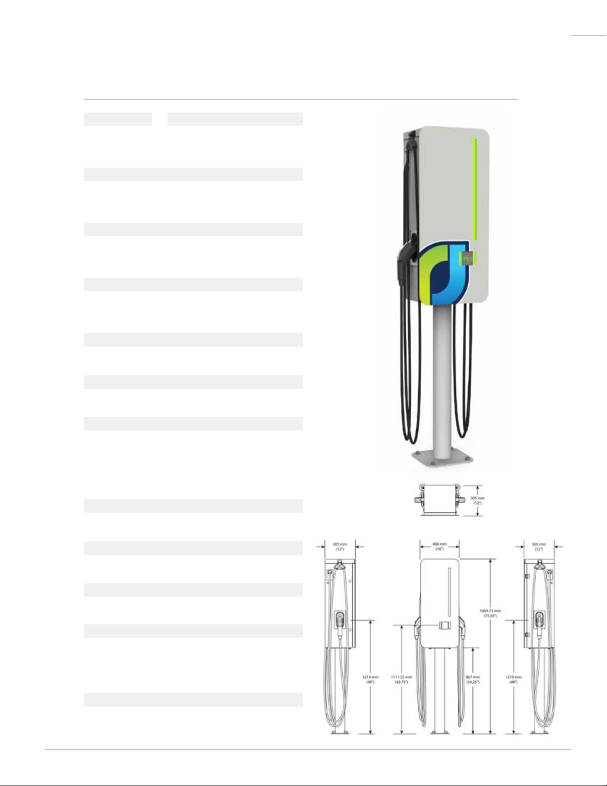
320 SERIES...........................................................................................................
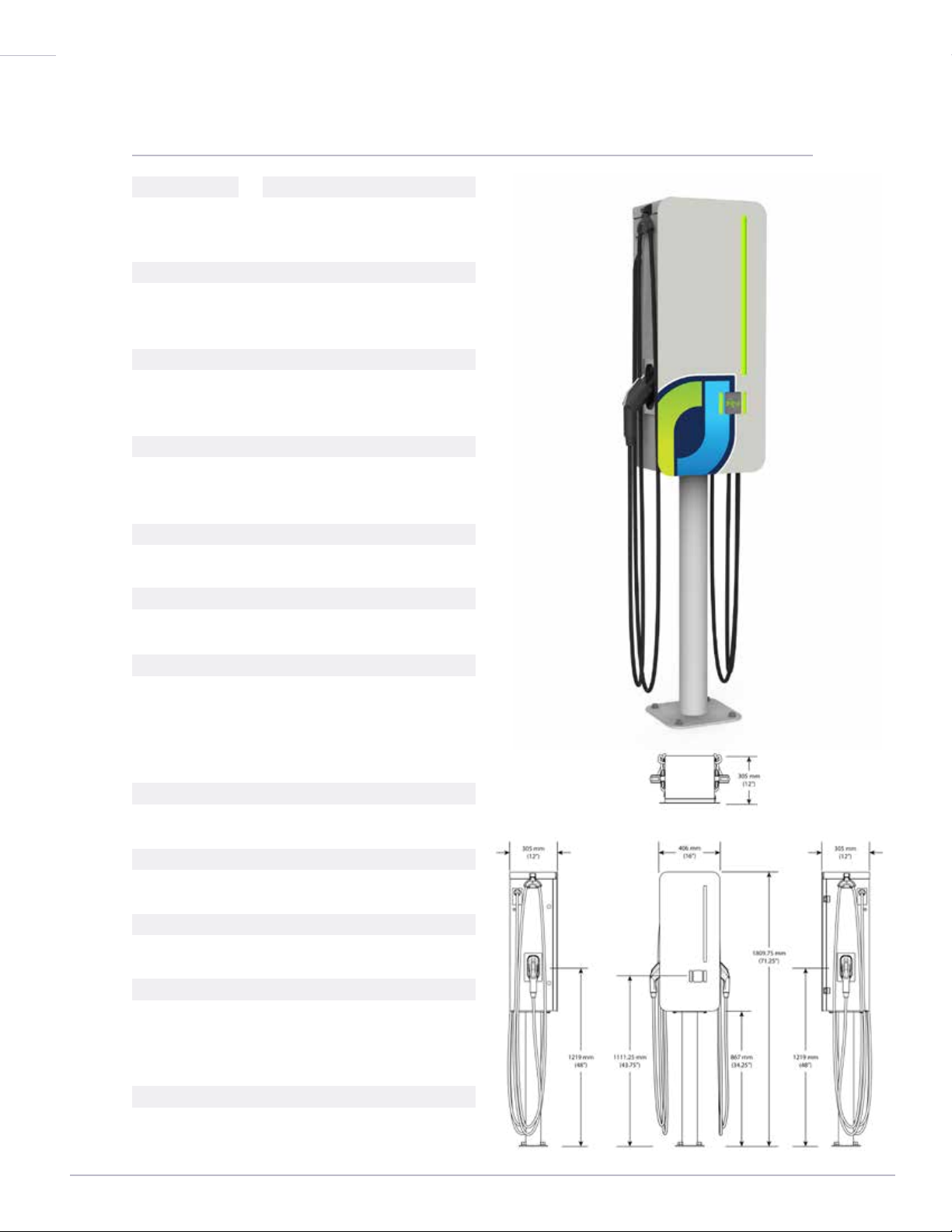
400 SERIES...........................................................................................................
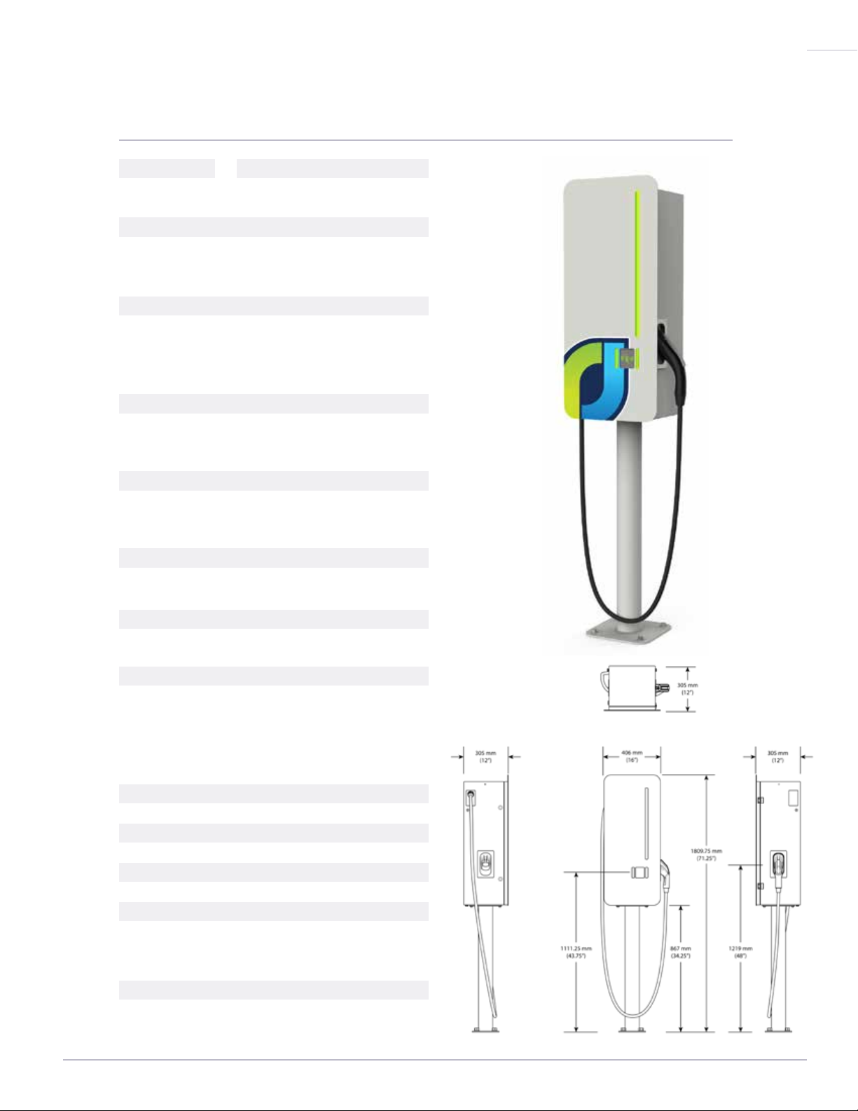
480 SERIES...........................................................................................................
800 SERIES...........................................................................................................
PARTS & COMPONENTS
PARTS LIST...........................................................................................................
EXTERNAL COMPONENTS & ASSEMBLY........................................................
INTERNAL COMPONENTS & ASSEMBLY.........................................................
INSTALLATION REQUIREMENTS
SITE SELECTION..................................................................................................
MOUNTING INSTRUCTIONS...............................................................................
WIRING INSTRUCTIONS.....................................................................................
COMMUNICATIONS.............................................................................................
OPERATING INSTRUCTIONS
GENERAL INFORMATION....................................................................................
NETWORK CHARGER INFORMATION.............................................................
NON-NETWORK CHARGER INFORMATION.....................................................
TROUBLESHOOTING..........................................................................................
MAINTENANCE & REPAIRS
GENERAL INFORMATION...................................................................................
CONTACT INFORMATION...................................................................................
STANDARD WARRANTY.....................................................................................
03
04
05
06
07
08
09
13
14
16
20
28
35
37
39
41
42
46
47
49
TABLE OF CONTENTS

3©Copyright 2020 Oasis Charger Corporation. All rights reserved.
This installation manual includes the latest information at the time of printing.
Oasis Charger Corporation reserves the right to revise this manual and its
JuiceBar Gen 3 charger products from time to time without further notice.
If you have questions about the use or installation of this product, contact
One of our knowledgeable team members will respond promptly.
We rely on our customers to help us improve our products and service. We
welcome your comments and suggestions. Please contact us by phone
at 860-308-2054 or send your comments or suggestions to support@
JuiceBarEV.com.
GENERAL INFORMATION
PUBLICATION NOTICE

4
©Copyright 2020 Oasis Charger Corporation. All rights reserved.
This symbol precedes a Warning, a Caution or
Important message.
Cesymbole précèdeun avertissement, unmessage d’avertissement oumessage
important.
WARNING Indicates a potentially hazardous situation that can result in
serious injury or death if it is not avoided.
AVERTISSEMENT indique une situation potentiellement dangereuse qui peut
entraîner des blessures graves ou la mort si elle n’est pas évitée.
CAUTION Indicates a situation that can damage equipment and possibly
result in injury.
ATTENTION indique une situation susceptible d’endommager le matériel et de
blesser.
IMPORTANT Indicates critical information pertaining to: local codes,
installation or operation of the equipment.
IMPORTANT indiqueinformationscritiques relativesà: codes locaux,l’installation
ou le fonctionnement de l’équipement.
This symbol means there is a Risk of Electric Shock
and precedes a Warning, Caution or Statement
Related to Wiring.
Ce symbole signifie qu’il y a un risque de choc électrique et précède un
Avertissement, Attention ou Instruction liées à câblage.
GENERAL INFORMATION
SYMBOLS & IMPORTANT
SAFETY MESSAGES

5©Copyright 2020 Oasis Charger Corporation. All rights reserved.
320 SERIES: 32A LEVEL 2
TECHNICAL SPECIFICATIONS
MODEL #
JB3.0-321
JB3.0-322
CERTIFICATIONS
TUV Rheinland
UL 2231-1, UL 2231-2, UL 2594
AC OUTPUT PER CONNECTOR
7.7 kW at 240VAC
6.6 kW at 208VAC
OPERATING TEMPERATURE
- 25° C to +50° C
- 13° F to +122° F
COMMUNICATIONS
Cellular, Ethernet
PROTOCOL
OCPP 1.6J
DIMENSIONS
71.25” Total Height with Pedestal
36.5” Total Height w/out Pedestal
16” Width Without Connectors
12” Depth
CORD LENGTH
18 feet
CONNECTORS
SAE J1772 Type 1
ENCLOSURE
Type 3R Aluminum
OPTIONS
Wall Bracket
Pedestal Mount
Branded Door Graphics
USER INTERFACE
LED Indicators
RFID Card Reader
DESCRIPTION
Single Connector Charger
Dual Connector Charger

6
©Copyright 2020 Oasis Charger Corporation. All rights reserved.
400 SERIES: 40A LEVEL 2
TECHNICAL SPECIFICATIONS
MODEL #
JB3.0-401
JB3.0-402
CERTIFICATIONS
TUV Rheinland
UL 2231-1, UL 2231-2, UL 2594
AC OUTPUT PER CONNECTOR
9.6 kW at 240VAC
8.3 kW at 208VAC
OPERATING TEMPERATURE
- 25° C to +50° C
- 13° F to +122° F
COMMUNICATIONS
Cellular, Ethernet
PROTOCOL
OCPP 1.6J
DIMENSIONS
71.25” Total Height with Pedestal
36.5” Total Height w/out Pedestal
16” Width Without Connectors
12” Depth
CORD LENGTH
18 feet
CONNECTORS
SAE J1772 Type 1
ENCLOSURE
Type 3R Aluminum
OPTIONS
Wall Bracket
Pedestal Mount
Branded Door Graphics
USER INTERFACE
LED Indicators
RFID Card Reader
DESCRIPTION
Single Connector Charger
Dual Connector Charger

7©Copyright 2020 Oasis Charger Corporation. All rights reserved.
480 SERIES: 48A LEVEL 2
TECHNICAL SPECIFICATIONS
MODEL #
JB3.0-481
JB3.0-482
CERTIFICATIONS
TUV Rheinland
UL 2231-1, UL 2231-2, UL 2594
AC OUTPUT PER CONNECTOR
11.5 kW at 240VAC
10kW at 208VAC
OPERATING TEMPERATURE
- 25° C to +50° C
- 13° F to +122° F
COMMUNICATIONS
Cellular, Ethernet
PROTOCOL
OCPP 1.6J
DIMENSIONS
71.25” Total Height with Pedestal
36.5” Total Height w/out Pedestal
16” Width Without Connectors
12” Depth
CORD LENGTH
18 feet
CONNECTORS
SAE J1772 Type 1
ENCLOSURE
Type 3R Aluminum
OPTIONS
Wall Bracket
Pedestal Mount
Branded Door Graphics
USER INTERFACE
LED Indicators
RFID Card Reader
DESCRIPTION
Single Connector Charger
Dual Connector Charger

8
©Copyright 2020 Oasis Charger Corporation. All rights reserved.
800 SERIES: 80A LEVEL 2
TECHNICAL SPECIFICATIONS
MODEL #
JB3.0-801
CERTIFICATIONS
TUV Rheinland
UL 2231-1, UL 2231-2, UL 2594
AC INPUT
Voltage: 208/240 VAC
Breaker: Rating 100A
Single Connector: 3 Wire (L1, L2 & G)
AC OUTPUT PER CONNECTOR
19.2 kW at 240VAC
16.6 kW at 208VAC
OPERATING TEMPERATURE
- 25° C to +50° C
- 13° F to +122° F
COMMUNICATIONS
Cellular, Ethernet
PROTOCOL
OCPP 1.6J
DIMENSIONS
71.25” Total Height with Pedestal
36.5” Total Height w/out Pedestal
16” Width Without Connectors
12” Depth
CORD LENGTH
9 feet
CONNECTORS
SAE J1772 Type 1
ENCLOSURE
Type 3R Aluminum
OPTIONS
Wall Bracket
Pedestal Mount
Branded Door Graphics
USER INTERFACE
LED Indicators
RFID Card Reader
DESCRIPTION
Single Connector Charger

9©Copyright 2020 Oasis Charger Corporation. All rights reserved.
PARTS LIST
Before proceeding with the installation of your Gen 3 Charging Station, please inspect
the product and confirm there is no shipping damage. If the unit is damaged or otherwise
Confirm receipt of any accessories ordered with the unit that may have been packaged
separately such as a pedestal mount, wall bracket, cord management system or a
precast foundation.
• JB 3.0
• Two (2) Door Keys
• One (1) Cam Key
• Three (3) Terminal Block Jumpers
• Wall Mount Bracket
• Four (4) Bracket-to-EVSE Bolts
• Four (4) Washers
• Stainless over Carbon Steel Pedestal with Standard Bolt Pattern
• Stainless over Carbon Steel Pedestal with Legacy EVSE to Gen 3 Bolt Pattern
• Concrete Precast Foundation with conduit Sweeps and Stainless Steel Studs
• Four (4) Stainless steel Nuts
• Four (4) Stainless steel Washers
The EVSE Package
Wall-Mount Bracket Package
Pedestal-Mount Package
Conversion Pedestal-Mount Package
Precast Foundation Package
PARTS & COMPONENTS

10 ©Copyright 2020 Oasis Charger Corporation. All rights reserved.
• Phillips head screw driver
• Flat head screw driver
• Wrench for pedestal to ground
• Wrench for pedestal to unit
• Wrench for wall bracket to wall
• Rotory hammer drill
• Shims
• Sealant
• Anchors
• EV simulator or an EV
• Level
Suggested Installation Tools
Pre-Work
Required Breaker Ratings
Breakers must be new.
This manual suits for next models
10
Table of contents
Popular Automobile Accessories manuals by other brands

ULTIMATE SPEED
ULTIMATE SPEED 279746 Assembly and Safety Advice

SSV Works
SSV Works DF-F65 manual

ULTIMATE SPEED
ULTIMATE SPEED CARBON Assembly and Safety Advice

Witter
Witter F174 Fitting instructions

WeatherTech
WeatherTech No-Drill installation instructions

TAUBENREUTHER
TAUBENREUTHER 1-336050 Installation instruction


