Oasis CO2739R User manual

SELF-CONTAINED REFRIGERATED SERVICE/SELF-SERVICE MODEL CO2739R
REV H DATE: 10/31/2022
USER MANUALS\99399_OASIS_USER MANUAL_CO2739R_REF_SVC-SELF-SVC_SELF-CONT_CASE
Model CO2739R Shown With Product For Illustrative Purposes Only
READ AND SAVE THESE INSTRUCTIONS
SCC P/N
99399
USER
MANUAL
Oasis
®
Structural Concepts Corporation ∙ 888 E. Porter Rd ∙ Muskegon, MI 49441 Phone: 231.798.8888 Fax: 231.798.4960 ∙ www.structuralconcepts.com

2
TABLE OF CONTENTS
OVERVIEW / TYPE / COMPLIANCE / WARNINGS / PRECAUTIONS / PLUGS / WIRING …….....…..
SHIPPING SUPPORT REMOVAL / GRILLE & TOE-KICK REMOVAL / REMOVING CASE FROM
SKID……………………………………………………………………………………………………….
CASE PLACEMENT / CASTER LOCKING & UNLOCKING OPERATION / START-UP AND
OPERATION ….…………...…...…..…………………………….…………….……………………….
MAINTENANCE FUNDAMENTALS: FRONT PANEL / FRONT GRILLE / FLUORESCENT LIGHT
FIXTURES …………………………………………………………………………………....……….…
MAINTENANCE FUNDAMENTALS, CONT’D: POWER CORD & PLUG, LED LIGHTS & FIXTURES
MAINTENANCE FUNDAMENTALS, CONTINUED: HONEYCOMB AIR DIFFUSERS ………………….
ELECTRICAL FUNDAMENTALS ………………………..………………………...……………….………….
REFRIGERATION FUNDAMENTALS ………………………………………………………………….……..
SERIAL LABEL LOCATION & INFORMATION LISTED / TECH INFO & SERVICE ……………...…….
TROUBLESHOOTING - GENERAL ………….……………………………………………………...………..
TROUBLESHOOTING - CONDENSING SYSTEM [TRAINED SERVICE PROVIDERS ONLY] …..…...
TROUBLESHOOTING - EVAPORATOR SYSTEM [TRAINED SERVICE PROVIDERS ONLY] ……....
ILLUSTRATED PARTS BREAKDOWN …………...………………..…………………………………………
PARTS LIST ……….……….……………………………………..……………………………………...………
CLEANING SCHEDULE ….....…………………………………………………...…………….…….….....…..
PROGRAMMABLE CONTROLLER INFORMATION ……….……………..……………….………………..
TECHNICAL SERVICE CONTACT INFORMATION / WARRANTY INFORMATION ..…….…...............
3-4
5
6
7
8
9
10
11
12
13
14
15
16
17
18
19
20

3
OVERVIEW
• These Structural Concepts merchandisers are
designed to merchandise pre-chilled packaged
products at 41 °F [5 °C] or less product temperatures.
• Cases should be installed and operated according to
this operating manual’s instructions to insure proper
performance.
• Improper use will void warranty.
TYPE I vs. TYPE II ENVIRONMENTAL CONDITIONS
This unit is designed for the display of products in ambient
store conditions where temperature and humidity are
maintained within a specific range.
• Type I display refrigerators are intended for use in an
area where environmental conditions are controlled and
maintained so that the ambient temperature does not
exceed 75 °F (24 °C) and 55% maximum humidity.
• Type II display refrigerators are intended for use in an
area where environmental conditions are controlled and
maintained so that the ambient temperature does not
exceed 80 °F (27 °C) and 60% maximum humidity.
• If unsure if your unit is Type I or II, see tag next to serial
label. See SERIAL LABEL LOCATION &
INFORMATION LISTED / TECH INFO & SERVICE
section in this manual for sample serial labels.
COMPLIANCE
• Performance issues when in violation of applicable
NEC, federal, state and local electrical and plumbing
codes are not covered by warranty.
• See below compliance guideline.
WARNINGS
• This sheet contains important warnings to prevent
injury or death. Please read carefully!
WARNING
Hazardous moving parts. Do not operate unit with covers removed.
Fan blades may be exposed when deck panel is removed.
Disconnect power before removing deck panel.
WARNING
Risk of electric shock. Disconnect power before servicing unit.
CAUTION! More than one source of electrical supply is
employed with units that have separate circuits.
Disconnect ALL ELECTRICAL SOURCES before servicing.
WARNING
Condenser Pan is Hot!
Disconnect and allow to cool
before cleaning or removing from case.
WARNING
ELECTRICAL
HAZARD
WARNING
KEEP
HANDS
CLEAR
WARNING
HOT
SURFACE
COMPLIANCE
This equipment MUST be installed in compliance with
all applicable NEC, federal, state and local
electrical and plumbing codes.
OVERVIEW / TYPE / COMPLIANCE / WARNINGS / PRECAUTIONS / PLUGS / WIRING - PAGE 1 of 2
ATTENTION
CONTRACTORS
WARNING: This product can expose you to chemicals, including
Urethane (Ethyl Carbamate), which are known to the state of
California to cause cancer and birth defects or other reproductive
harm. For more information go to P65Warnings.ca.gov.

4
OVERVIEW / TYPE / COMPLIANCE / WARNINGS / PRECAUTIONS / PLUGS / WIRING - PAGE 2 of 2
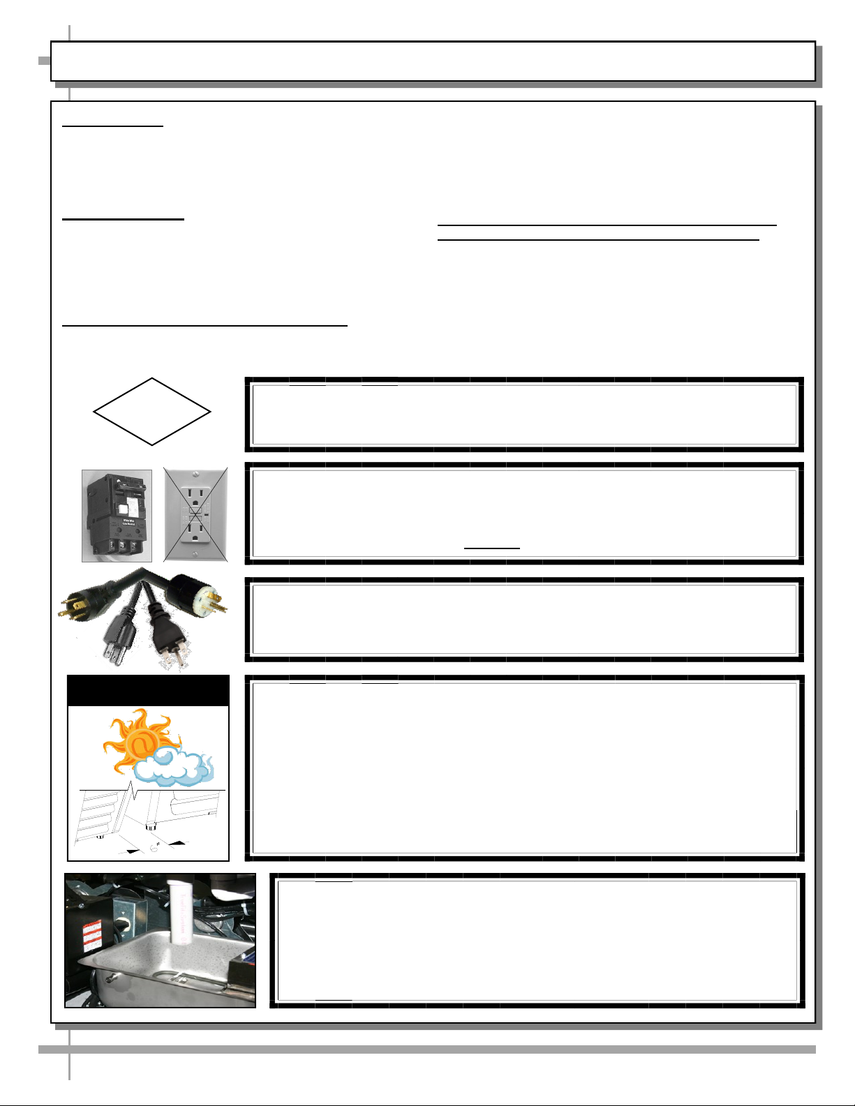
CAUTION! GFCI BREAKER USE RECOMMENDATION
If N.E.C. (National Electric Code) or your local code
requires GFCI (Ground Fault Circuit Interrupter) protection,
the use of a GFCI breaker is strongly recommended.
PRECAUTIONS
• This sheet contains important precautions to prevent
damage to unit or merchandise. Please read carefully!
• See previous page for specifics on OVERVIEW, TYPE,
COMPLIANCE and WARNINGS.
WIRING DIAGRAM
• Each case has its own wiring diagram folded and in its
own packet.
• Wiring diagram placement may vary; it may be placed
near ballast box, field wiring box, raceway cover, or other
related location.
REFRIGERANT DISCLOSURE STATEMENT
• This equipment is prohibited from use in California with
any refrigerants on the “List of Prohibited Substances”
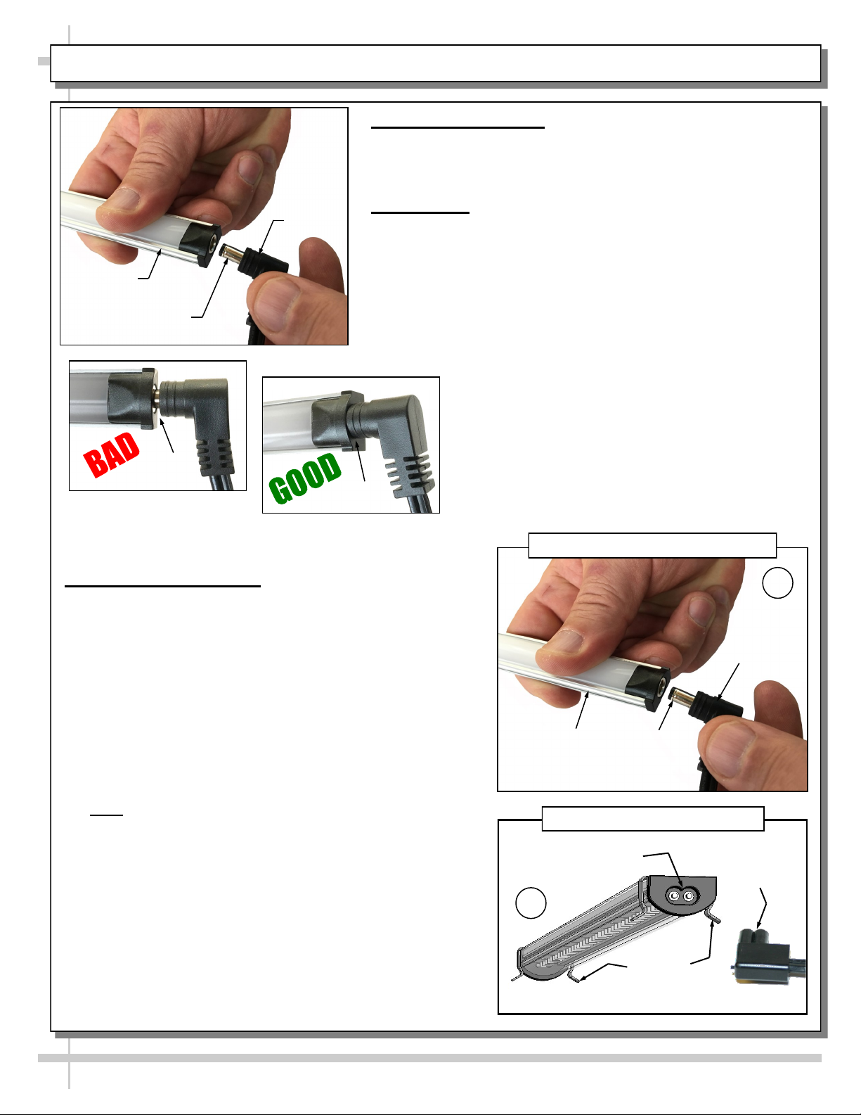
CAUTION! POWER CORD AND PLUG MAINTENANCE
Risk of electric shock. If cord or plug becomes damaged,
replace only with cord and plug of same type.
CAUTION! LAMP REPLACEMENT GUIDELINES
LED lamps must reflect specific size, shape and overall design.
Any replacements must meet factory specifications.
for that specific end-use, in accordance with California
Code of Regulations, title 17, section 95374.
• This disclosure statement has been reviewed and
approved by Structural Concepts and Structural Concepts
attests, under penalty of perjury, that these statements
are true and accurate.
CAUTION! DO NOT RELY ON THERMOMETERS OR
THERMOSTATS FOR PRODUCT (FOOD) TEMPS.
• Thermometers & thermostats reflect air temps ONLY.
• For ACTUAL product (food) temperatures, use a
calibrated food probe thermometers ONLY.
• For accurate readings, DO NOT use infrared food
thermometers.
CAUTION
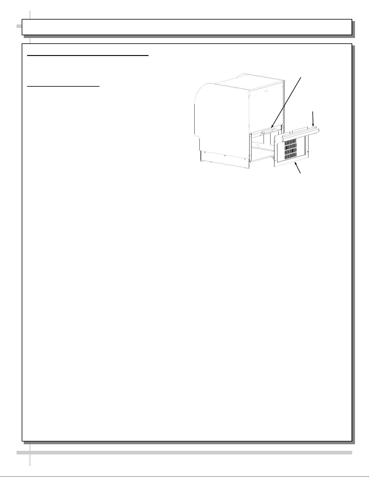
CAUTION! ADVERSE CONDITIONS / SPACING ISSUES
• Performance issues caused by adverse conditions are NOT warranted.
• To prevent damage to end panels due to condensation, apply industrial grade
silicone sealant and tightly join to opposite end panels. When not adjoining
cases, keep end panels at least 6” away from walls and structures. Rear
panels must also be kept at least 6” from walls and structures.
• Case must not be exposed to direct sunlight or any heat source.
• To maintain proper case temperature, keep case at least 15-feet from exterior
doors, overhead HVAC vents or any air curtain disruption.
• Self-contained case clearance: 6” min. air intake / 6” min. air discharge.
CAUTION
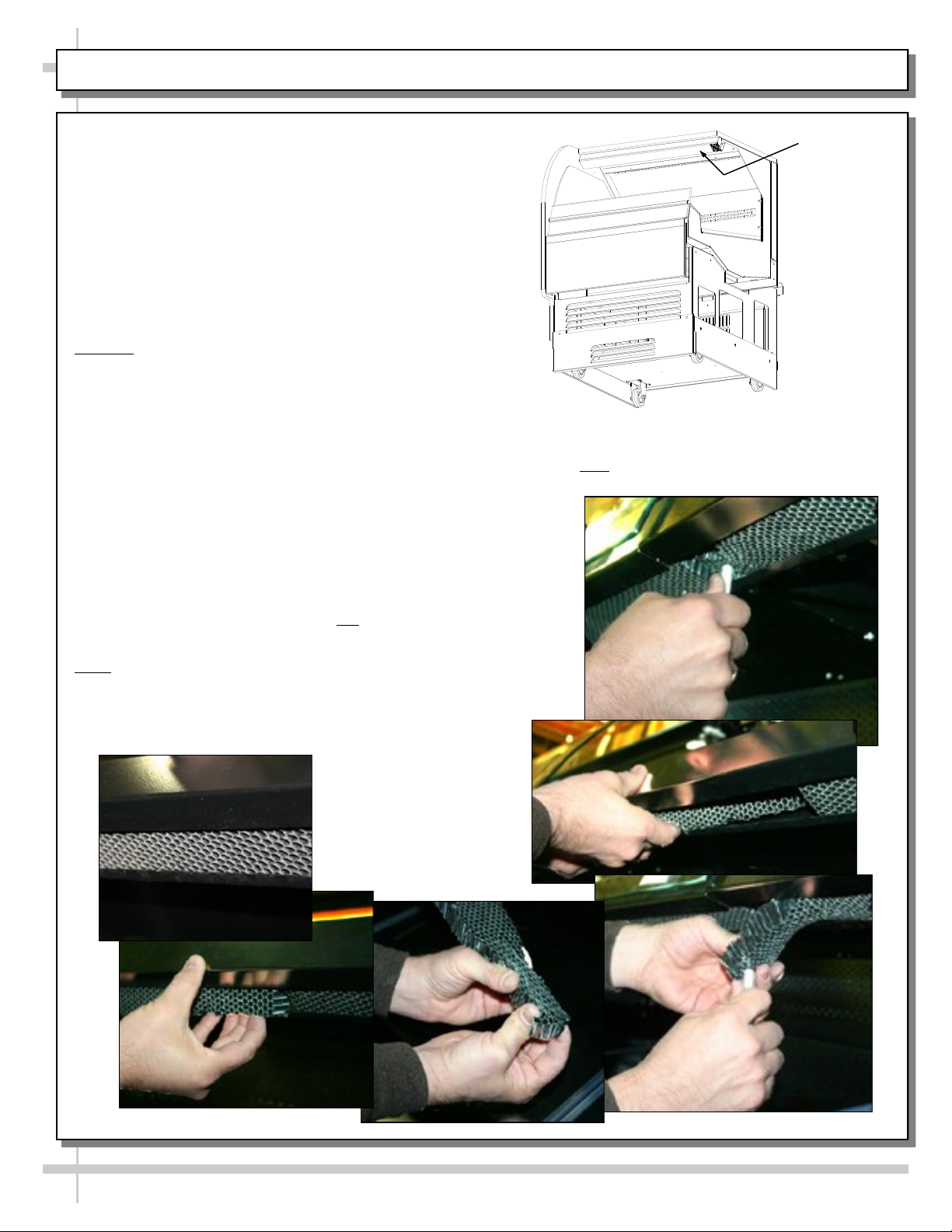
CAUTION! CHECK CONDENSATE PAN, ITS POSITION & PLUG!
Water on flooring can cause extensive damage!
• Before powering up case, check that condensate pan is positioned
directly under case’s condensate drain.
• Before powering up case, check that condensate pan’s electrical plug is
SECURELY connected to condensate system’s receptacle.
• If wicking material is used in condensate pan, check that it is secure.

5
SHIPPING SUPPORT REMOVAL / GRILLE & TOE-KICK REMOVAL / REMOVING CASE FROM SKID
1. Removing Caster Shipping Support (or
Shipping Support Bracket) Attached To Skid
• Remove screws holding shipping supports (or
shipping support brackets) to skid. Discard.
• Note: Shipping supports and/or brackets will vary
in size, shape, material and location depending
upon case type and model.
• See illustration below-left.
2. Remove Front Grille, Rear Grille and Side
Panels Before Removing From Skid
• Grilles and lower side panels may be attached to
case during shipment.
• If they are attached to case, they must be
removed prior to skid removal.
• Screw removal may be required.
• After case is in position (and level and plumb, if
case has levelers), you must reattach these
components to case.
3. Remove Case From Skid
• To prevent damage, support case (while sliding
it toward edge of skid).
• For units with casters, casemay be rolled off skid
via ramp (as shown below-right) and into
position.
• For units with legs/levelers, carefully slide case
off skid (at one end). Then slide skid out from
under case at other end (as shown immediately
below).
• Use adjustable wrench and/or pry bar to level.
• Case must be level & plumb after it is in position.
Side View of Case (With End Panel
Removed For Illustrative Purposes Only)
Note: Front Grille, Rear Grille and Side Panels
Must Be Removed Prior To Skid Removal To
Prevent Damage To Components!
Pry Bar
Adjustable
Wrench
Sample Caster Shipping
Support (To Be Removed
And Discarded)
Sample Shipping
Bracket (To Be Removed
And Discarded)

6
CASE PLACEMENT / CASTER LOCKING & UNLOCKING OPERATION / START-UP AND OPERATION
1. Caster Locking / Unlocking Operation
• After case has been moved to proper location, if
casters have locking feature, they may be locked
to prevent case from moving out of position.
• To lock caster (from the unlocked position),
press down on each RAISED caster lever (as
shown in illustration below-left). Casters will lock
in place.
• To unlock casters (from the locked position),
press down on the RAISED caster lever (as
shown in illustration below-left). Casters will now
be unlocked.
2. Merchandiser Start-Up and Operation
• Do not use an extension cord with this
appliance.
• Do not operate this equipment with a damaged
cord, plug or outlet.
• Insure the main power switch is off.
• Plug cord into a certified 120V electrical outlet
with ground.
• Turn main power on.
• Remove upper front panel (see maintenance
for panel removal). Switch is on the right
side of case.
• Coil fan should turn on.
• From inside of the case, check for discharge
air from front baffle, to confirm that the fans
are functioning properly.
• When the case is in a start up mode or has
been idle for a long period of time,
Main Power Switch
the unit will require 75 minutes in order to pull
-down temperature.
• The lights should come on at the same time.
• First time lighting may require a short warm
up period for the bulbs. Slightly dim or a
flickering of new bulbs is normal.
• It is recommended that the self contained
refrigerated cases maintain front and rear
airflow clearance of approximately six inches.
• Obstruction or restriction of air can void
warranty.
• The interior case temperature reaches 2 °C to
5 °C / 35 °F to 41 °F.
• Note: The case temperature is set at the
factory, as determined by the case size. The
temperature is controlled by a thermostat.
If a temperature setting change is required,
refer to the instructions for the Temperature
Control Programming operating section of
this manual.
• Note: Set point should be 4.5 °C / 40 °F. This
will maintain the product temperature range.
Settings lower than 4.5 °C / 40 °F can cause food
items to freeze.
Casters
Locked
Casters
Unlocked

7
MAINTENANCE FUNDAMENTALS: FRONT PANEL / FRONT GRILLE / FLUORESCENT LIGHT FIXTURES
1. Removing the Front Panel
• Lifting the panel from lower edge upward
approximately a half inch into a channel lip,
disengages the support taps on the lower edges.
• Pivot out lower edge approximately one inch and
lower panel to remove.
2. Removing the Front Grille
• Lifting the grille upward approximately a half inch
disengages a top support flange and the support
taps on the back lower side of the grille from the
frame .
• Pivot out lower edge and remove grille.
3. Light Fixtures - Fluorescents
Removal of lamp:
• Rotate lamp (1/4 turn) either direction to
disengage (upper or lower) pins/contacts from
lamp mounting sockets.
• Remove bulb buy applying even pressure from the
back side at the bulb ends and pulling the
remaining contact from the sockets.
Installation of lamp:
• Align pins with slot.
• Insert pins into socket by rotating the bulb 1/4 turn
to secure either the (upper or lower) pined
contacts into the sockets.
• Rotate the remaining bulb contacts (1/4 turn) into
the remaining lamp mounting socket contacts.
4. Light Fixtures - Power Cord & Plug, LEDs, Etc.
• See next page.
Channel Lip
Support Tabs
Upper Front Panel
Front Grille
Support Rest
Support Tabs
Support Flange
Lamp Pins
Light Socket Light Fixture

8
MAINTENANCE FUNDAMENTALS, CONT’D: POWER CORD & PLUG, LED LIGHTS & FIXTURES
4. Power Cord and Plug
• Power cord and plug (for LED lights) locations vary
depending upon model.
• Caution! You must plugged in an approved outlet!
5. LED Lights
• LED lights are located at both header and shelving of case
(as shown below).
• Check that ALL of the light plugs are properly connected to
the LED light.
• Plug must be inserted ALL THE WAY into the LED light
orifice (with no gap) to work properly.
• See TROUBLESHOOTING section in manual if LED lights
malfunction.
No Gap
Gap
6. LED Style Light Fixtures
Removal of faulty LED light:
• LED lights rarely require change-out.
• To remove faulty LED light, simply grasp light near
retaining spring and carefully pull away from its spring.
Disconnect plug from LED’s socket.
• Contact Structural Concepts’ Technical Service
Department for replacement parts (see Technical
Service section of this manual for information).
Replacement of LED light:
• To replace LED light fixture, simply insert new LED light
at proper position (socket must be near plug). Carefully
snap into metal springs so LEDs are held firmly in place.
• Note: LED light and plug must be connected in a
specific manner or they will not work.
A. Certain plug designs (“barrel type”) merely require that
plug be pushed all the way in.
B. Other plugs require “oval edge” of plug to
connect to oval edge of LED light.
• See illustrations at right.
LED Light
Plug
LED’s Barrel
Shaped Insert
LED’s Oval Form Plug’s
Oval Form
--- LED Plug & Light Fixture ---
Retaining
Springs
Plug
A
B
LED’s Barrel
Shaped
Insert
LED
Light
“B-Shaped” LED Plug & Light Fixture
“Barrel-Shaped” LED Plug & Light Fixture

9
MAINTENANCE FUNDAMENTALS, CONT’D: HONEYCOMB AIR DIFFUSERS
7. Honeycomb Maintenance
Preventive maintenance should be performed every
30 days unless conditions warrant a more frequent
replacement cycle.
Honeycomb Air Diffuser Removal
Honeycomb is located in discharge air duct.
A. Wedge a non-metallic device of suitable strength (such
as a ballpoint pen) between the honeycomb and the end
panel.
Caution! Use care not to dislodge the heating wire (that
prevents condensation on the lamp assembly).
B. Apply pressure to collapse the honeycomb to allow it to
be pulled out of honeycomb retainer.
C. Pry downward and away from honeycomb retainer.
• Clean honeycomb with warm water and soap solution.
• Submerse if necessary.
• Use brush to dislodge stubborn or sticky residue.
• Dry by using vacuum’s blow mode (vs. suction mode).
Honeycomb Air Diffuser Installation
D. Squeeze honeycomb to allow it to fit into honeycomb
retainer.
E. Carefully slide honeycomb into place.
F. Adjust honeycomb so that it fits flat against retainer.
It must not be wavy or out of position.
Note: For honeycomb air diffusers in other locations,
these same general instructions apply.
A
B
C
D
E
F
Note: Model features and options may vary.
Honeycomb
Air Diffuser

10
ELECTRICAL FUNDAMENTALS
1. Electrical: Access and Connections
Warning, disconnect power before providing
maintenance and service to unit.
2. Light Ballast Access
• Remove three screws from the rear wire
channel.
• Remove four screws from the rear grille.
Rear Grille
Wire Channel
Ballast

11
REFRIGERATION FUNDAMENTALS
1. Temperature & Defrost Control
• The case temperature is set at the factory, as
determined by the case size. The temperature is
controlled by a thermostat. If a temperature setting
change is required, follow the instructions for the
Temperature Control Programming Steps in the
technical information section of this operating
manual.
• If service is required to the temperature control
unit, call Structural Concepts. This maintenance
should be performed by a certified technician.
2. Evaporator Fan Access
• Remove lower decking. A finger hole is provided to
assist in lifting up and pulling out deck.
3. Expansion Valve Access
• Remove lower decking. A finger hole is provided to
assist in lifting up and pulling out deck.
• Remove fan shroud assembly.
• Unplug the fan at the shroud support.
• Remove four screw knobs from the fan shroud.
• Carefully remove shroud to avoid damage to
mirrors or front air deflector.
4. Refrigeration:
Access and Connections
• Assembly or disassembly and servicing to be
accomplished by licensed refrigeration
contractor.
• Refer to maintenance fundamentals for access.
• Remove front panel.
• Remove front grille.
Front of Case
Sight Glass
Refrigerant Service Fittings
Hot Gas Evaporator
Temp. Controller
Lower Decking
Evaporator Fan
Fan shroud

12
SERIAL LABEL LOCATION & INFO LISTED / TECH INFO & SERVICE / REFRIGERATED CASES ONLY
--- Sample Serial Label For Refrigerated Cases ---
MODEL NRS3648RXV-SAMPLE
SERIAL NO. 12345X30DZ098765
TYPE II DISPLAY REFRIGERATOR: THIS EQUIPMENT IS INTENDED FOR USE IN AN AREA
WHERE THE ENVIRONMENTAL CONDITIONS ARE CONTROLLED AND MAINTAINED SUCH
THAT THE AMBIENT TEMPERATURE DOES NOT EXCEED 80 °F (27 °C).
888 E. Porter Rd - Muskegon, MI 49441
3048256
Conforms to UL Std. 471
Conforms to NSF/ANSI Stds. 2 & 7
CERTIFIED TO CAN/CSA
STD C22.2 NO 120
ELECTRICAL RATING
REFRIGERANT
DESIGN PRESSURE
MINIMUM CIRCUIT AMPACITY
MAXIMUM OVERCURRENT
120/1/60 16 A
R513A AMOUNT 50 OZ
HIGH 186 LOW 88
20A
20A
Super Heat Temp 6-8 °F FOR PARTS AND SERVICE
Defrost 6 defrosts per day, 45 °F CALL 1-800-433-9490
Serial Label Location & Information Listed /
Technical Information & Service
• Serial labels are affixed at a wide range of places
(on the header, near thermostat, at case rear,
behind panels/toe-kicks, on electrical boxes, etc.).
• Serial labels contain electrical, temperature and
refrigeration information, as well as regulatory
standards to which the case conforms.
• Sample serial label shown below.
• For additional technical information and service, see
the TECHNICAL SERVICE page in this manual for
instructions on contacting Structural Concepts’
Technical Service Department.
Reveal
Harmony
Fusion
Impulse
Addenda
Blend
Grocerant
Oasis
Sample QR Code
SCAN FOR PRODUCT LITERATURE

13
Problem Solution
Alarm Going Off See alarm and fault codes of temperature controller.
Product is Drying Out Check the relative humidity in the store.
Water on the Floor Check the drain trap is free of debris.
Check that the condenser hot gas evaporator for cleanliness.
Excessive Fan Noise Check that the case is aligned, level and plumb.
Check that nothing is obstructing the blade rotation.
Check that the fan shroud is properly secured.
System is not Operating Check that the utility power is on.
Check that the MAIN power switch is on.
Check the circuit breaker box for tripped circuits.
Temperature Controller
Has No Illumination
Check connections on power supply contactor board.
Check fuse on power supply contactor board.
Fans Not Working Check that the power is on.
Check that fans are plugged in at the fan shroud.
Faulty motor.
Case Lights Not Working Check bulbs for proper installation and connection.
Check for burned out bulbs.
Clean dirt and dust from the bulbs to prevent flickering.
Faulty ballast.
Not Holding Temperature If a large amount of warm product was added to the case, it will take time for
the temperature to adjust.
The temperature will change during defrost mode but will return to normal.
Check that the case is not in the sun or near a heat or air-conditioning vent.
Case may be located too near store’s outside doors.
TROUBLESHOOTING - GENERAL

14
TROUBLESHOOTING - CONDENSING SYSTEM (BY TRAINED SERVICE PROVIDERS ONLY)
CONDITION TROUBLESHOOTING
Head Pressure Too High Check that the condensing coil is not dirty or covered.
Check that condensing fans are working.
Check that refrigerant is not overcharged.
Perform sub-cooling check and verify that no contaminates are in system.
Check that liquid line filter dryer is not plugged.
Check that close-offs are intact (around condensing coil) and that air is not
recirculate.
Check that store ambient temperature isn’t above maximum allowed.
See OVERVIEW / TYPE / COMPLIANCE / WARNINGS / PRECAUTIONS /
WIRING / PLUGS section in this manual.
Head Pressure Too Low Check if sight glass is flashing or showing low charge.
Check that suction pressure isn’t too low.
Check that compressor reed valves aren’t bad. Look for high suction/low head
pressure. Perform pump-down.

15
TROUBLESHOOTING - EVAPORATOR SYSTEM (BY TRAINED SERVICE PROVIDERS ONLY)
CONDITION TROUBLESHOOTING
Low Suction Pressure Check if sight glass is flashing or showing low charge.
Check that expansion valve (TXV) isn’t restricted. Check element charge.
Check that liquid line or filter isn’t restricted. Check that refrigeration lines
and/or hoses are not kinked on either high or low sides.
Check that evaporator fan motors are working.
Check that superheat is between 6 °F to 8 °F.
Check that there is no air recirculation around evaporator coil.
Check that evaporator coil is not iced up.
High Suction Pressure Check for refrigerant overcharge.
Check that compressor reed valves aren’t bad. Look for high suction/low
head pressure. Perform pump down.
Check that the “cooling load” isn’t high. Product must be pre-chilled before
placing in refrigerated section of case.
Check that case is at least 15-feet from exterior doors, overhead HVAC
vents or any air curtain disruption.
Check that unit is not exposed to direct sunlight via windows or any other
heat source (ovens, fryers, etc.).
Check that superheat adjustment isn’t low.
Check TXV bulb installation
a. Poor thermal contact.
b. Warm location.

16
ILLUSTRATED PARTS BREAKDOWN
4
8
2
6
7
15
13
5
3
14
9
1
17
12
11
10
16

17
PARTS LIST
1Top Board 10 Light Ballast
2End Panel 11 Wire Channel
3End Panel Mirror 12 Rear Grille
4Air Deflector Glass 13 Temperature Controller
5Single Pole Switch 14 Fan Motor, Evaporator
6Front Panel 15 Deck Pan
7Bumper Insert 16 Lamp Bulb
8Front Grille 17 Honeycomb
9Bumper End Cap

18
Cleaning Daily Weekly Monthly Task
Clean Case Exterior X
The acrylic must be cleaned with a mild soap and
water solution and a soft cloth. Never use a
household cleaner on acrylic.
Clean Case Interior X
Clean glass shelves and mirrors with a household or
commercial glass cleaner. The deck can be cleaned
with a warm soap and water solution.
XRemove the deck and clean with soap and water.
XRemove rear doors and clean with a household or
commercial cleaner.
X
Vacuum tub under deck or soap and water if
necessary. To flush out the tub, disconnect power to
the case. Remove the ABS deck and the fan shroud.
Note: Be sure to plug fans back in after cleaning and
before installing decks.
XKeep drain clean and free of debris which could clog
the drain and rob the case of needed refrigeration.
Clean Condensing Coil XVacuum grille area on back of case.
X
Using air pressure if available, or an industrial
strength vacuum, clean the dust and dirt that collects
on the condenser coil.
CLEANING SCHEDULE

PROGRAMMABLE CONTROLLER (SELECT, CLICK ON OR SCAN QR CODE FOR INFORMATION)
19
Carel® iJF Platform
Carel® PJEZ Platform Carel® ir33 Platform
Dixell® XM670K-XM679K Platform
To Access Information About The Programmable
Controller That Is Used On Your Case,
Follow These Instructions:
> If Viewing This Document on Smart Phone, Tablet
or Computer, Select/Click On The QR Code at Right.
> If Viewing This Document In Print (Hard Copy),
Scan The QR Code at Right With Your Smart Phone
or Tablet.
Determine Which Programmable Controller Is On Your Case (Controllers
That Are Commonly Used By Structural Concepts Are Shown Below).
Your Particular Programmable Controller May Differ.

STRUCTURAL CONCEPTS TECHNICAL SERVICE CONTACT INFORMATION & LIMITED WARRANTY
20
TECH SERVICE/WARRANTY CONTACT INFO:
1 (800) 433-9490 / EXTENSION 1
DAYS/HOURS AVAILABLE:
MONDAY - FRIDAY (CLOSED HOLIDAYS)
8:00 a.m. TO 5:00 p.m. EST
YOU MUST HAVE THE FOLLOWING INFO AVAILABLE
BEFORE CONTACTING STRUCTURAL CONCEPTS:
SERIAL NO. / MODEL NO. / STORE NO. / STORE
ADDRESS / DETAILS (PHOTOS, LEAK LOCATIONS,
DAMAGE, STORE’S AMBIENT CONDITIONS, ETC.)
To Access The Limited Warranty To Your
Case, Follow These Instructions:
> If Viewing This Document on Smart Phone,
Tablet or Computer, Select/Click On The QR
Code at Right.
> If Viewing This Document In Print (Hard
Copy), Scan The QR Code at Right With Your
Smart Phone or Tablet.
Table of contents
Other Oasis Commercial Food Equipment manuals
Popular Commercial Food Equipment manuals by other brands

Prince Castle
Prince Castle DHB2PT-20PUBGBN Operation manual

True
True TCGG-36-S-LD installation manual

Dover
Dover Hillphoenix PF-H Installation & operation manual

Rational
Rational SelfCooking Center Applications manual

Foster
Foster EP Series Operation instructions

Blueair
Blueair BAPP44 Installation & operation manual

Victor
Victor Ambassador AMB1 manual

Piper
Piper AP PROOFER Installation and operating manual

INOXPA
INOXPA SILPIG S0120 Installation, service and instructions

MINERVA OMEGA
MINERVA OMEGA C/E 652 operating instructions

Tefcold
Tefcold BK Series Technical manual

Nordcap
Nordcap MORETTI FORNI iRoll Series instruction manual