Oasis Landscaper 12 User manual

CONTROLS
Installation
and
Operating Manual
Please read these instructions carefirlly
to obtain maximum benefit of this controller.

il :r-----1- ll
lt-. . _
h"-mll
li@l
h,aiJl
Gardener 4,/6,/g
Landscaper 1Zl6
Gontrollers
Parkmaster 32 station
Massat 32 station
Durdee 6-9
Sentinel 4/6,/8
PfC8l 6 stalion
PIC82 12 & l8 station
PTC83 24, 30, 36 & 42
station
B0ss
#.'m
BOSS6&l2slarion

TABI,E Of CONTENTS
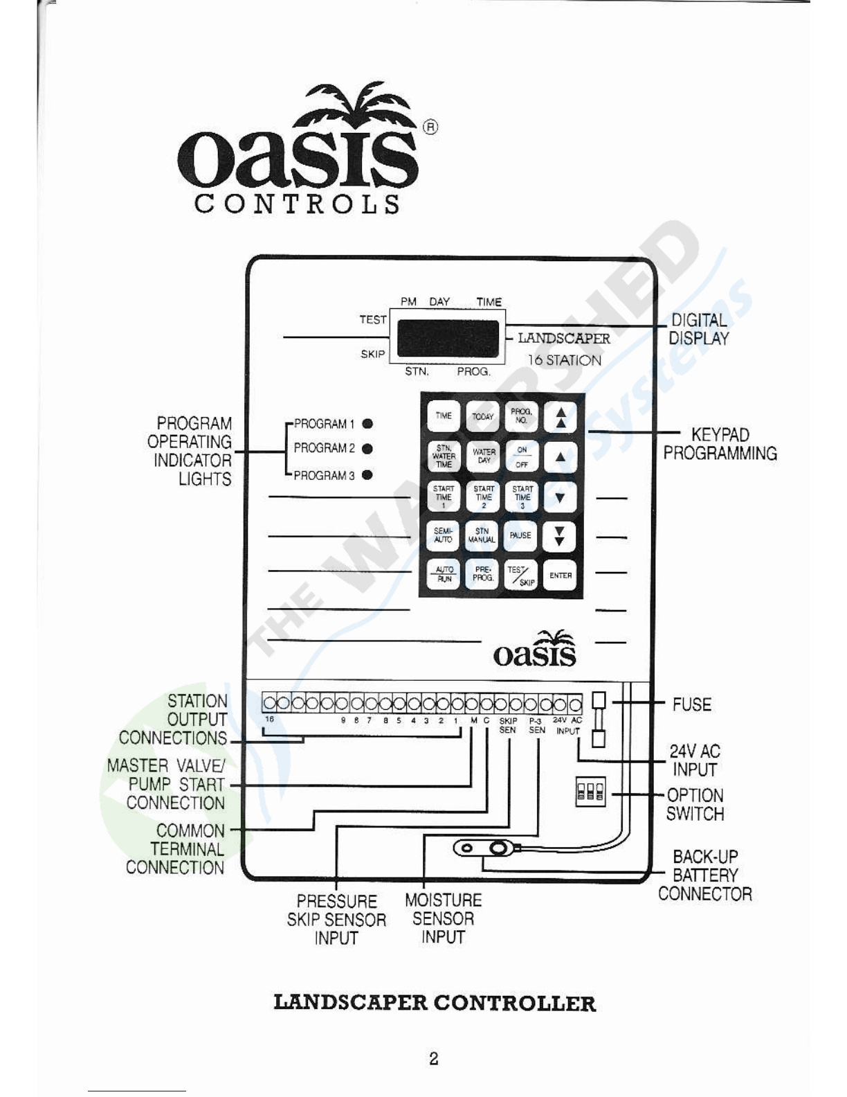
Unil Diagrffi ............-..............-.......-.............-.............,,,................-. 2
(e}?adGlossary.............-......--.............................-...,,...........--.....-..3
IBtarhtion Inshcliom
Moutinq$eControUe!,,.,,,,,,..,,,,..,,,...-.,...............-......-...4
Eleclrica1Hoo1up,,,.,,,,,,..,,,,,...,,,,..,......................__......_...4
Field Wiring Comectiong
Prepdation...........................-.....-......................................5
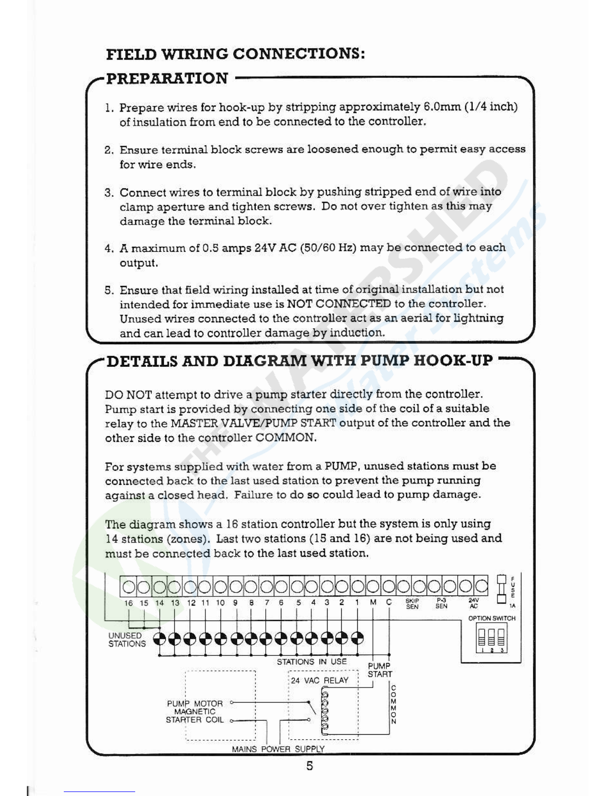
Details and Diaqya..........................................._......_....., 5
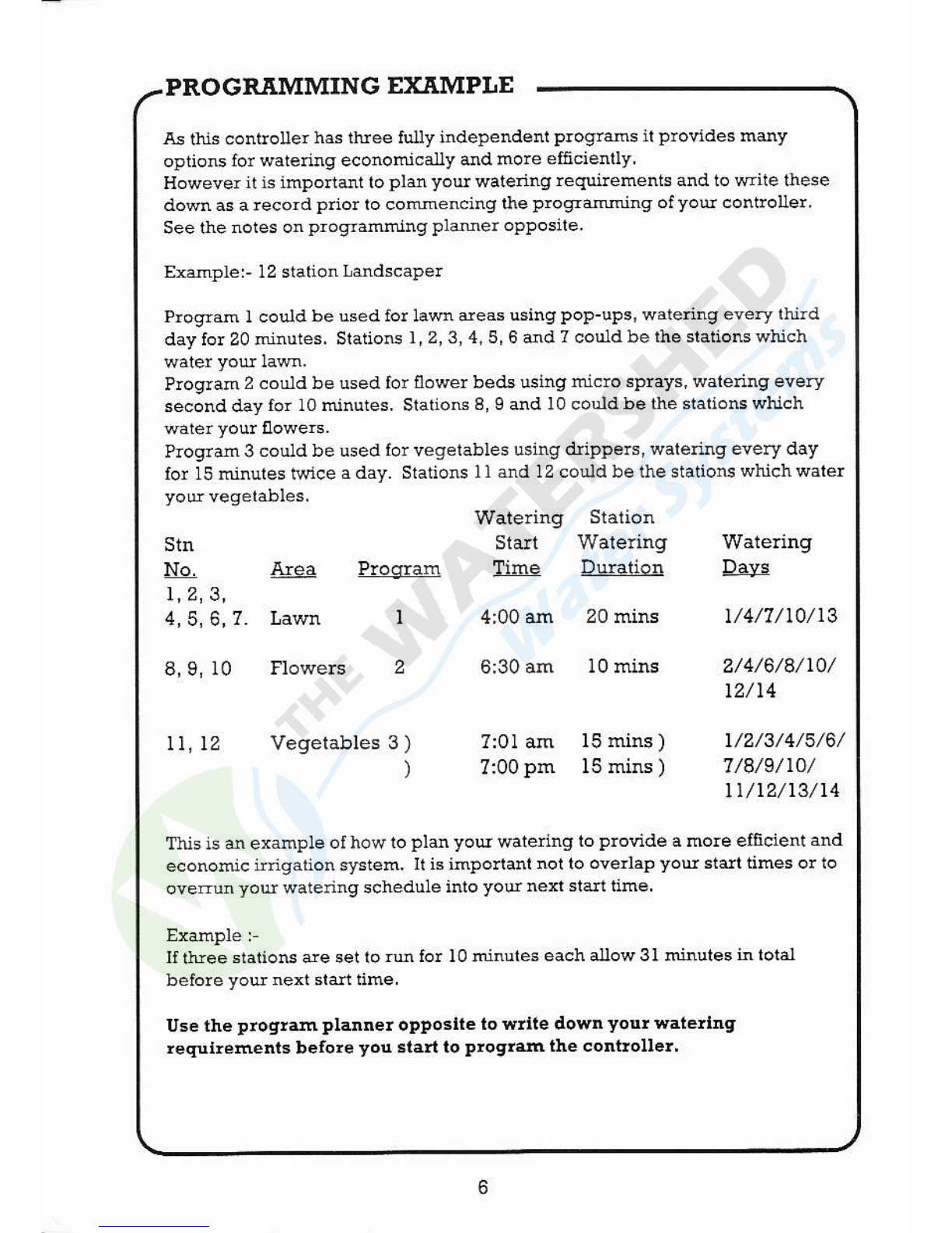
PlogrammingExample.-.............-.......-.............................................6
Progrming PlNer ...,,,,...,,.,,........,.,,....,,....-........-...............-....,,, 7
Progrming lhe ControUer
set up ............. ........... .. .,.......,........................-................ I
PowerupDisp]ayS1aius..,.....,,,.......................................-.8
Set Crenl Tim€ ..............-.............-................,........ ......-. I
Ser Crenl Day ,...................... ......-.......-.......-.............,,... a
SeiProgr 1 .......................,,,....,,...,.....................-..........9
Slep I Sel StationWalerinqfifre,,.,,,...-.................-....,,...,, I
Step 2 Sel WarennqDa]T......-..............-.......,..,.................. I
Step 3 Set SIan Time l,2 and 3 ...-..............,..,,................. 10
SetProqtan2and3..................-................-........-.....,...... l0
Sel Automatic PrcgramMode,....,....-...............--............,, l0
Changing iheAutomatic Progrd ..-.............,.,.........-...... I I
Sel Pre-prooams l, 2 dd 3......................................-...... ]l
SemiAulomaticOperation....................-.......,................-.12
Single SIalioiMatual,.,,....,,,,....,,..,................................. l2
TesiCycle.....,......,....,,,...,,,,,,....,,..,.,...........-........-......-.... l2
PalseFaciuly-.....--......,.....,,,,,.......-......-.....12
Rain OIfMode.....-...............
Emelgencystop...............-...........................,,,--.......-...... 13
Display Run Status ....-.....................-................-........-..,,,, l3
Ioop Operation inProgle 3,...........,...................._........ 14
Progrffiable Delay bet'reen stalions h ProqTm 3 ...... l5
SkipDetay..............-......-.............-................-.............,.... 15
SeEorActivaioa..,....,...-............................................,.... 16
BackupBattery.....-.......-......-............,,.......,,........-........... 16
Ehergency Bac! up Plogram,,,,..,......................-............ l6
Ele.dcalSpecificatioG.............-.......-............--........... .................. l7
la!llfjndingGuide...........-......-.....................-.......-...,.................. 18
Spde Progrming Plamer.......................................... t9, 20

;fift.^
OASIS
CONTROLS
PFOGRAM
OPEMTING
INDICATOB
LIGHTS
DIGITAL
D]SPLAY
KEYPAD
PROGRAI,IMING
STATION
OUTPUT
CONNECTONS
N,4ASTER VALVE/
PUI,IP START
CONNECTION
C0l\41\4ON
TEFI,4INAL
CONNECT]ON
FUSE
24V AC
INPUT
OPTION
SW]TCH
BACK.UP
BATTERY
PFESSUFE I4OISTUFE
SKIP SENSOR SENSOR
INPUT INPUT
I.ANDSCAPER CONTROLI,ER
CONNECTOR

KEYPAD GI,OSSARY
Used to set Clock Time.
Used 1o select progllam.
Used to sel walering day
Usedto set the tusl wateling
Used io set wateling day
calendar ON o! OFF ard to
manually turn slations
"ON' or "OFF .
Used lo set the second
wateling cycle siart time,
tr
sl,ow
G;Fl Used to ser the rlurd watennd
l"iJl ;;;.:."),;;: " """- " r.o_l used ro msuaxy ope€'e a
L:jl ptosrM
Used to m@ually opelate a
Sets the controller for autohalic
operation. Also displays the
curent slalion waiedng & the
wateling duation remainirg.
sf,ow FAsr
decrease decrease
Used lo suspend a walering
cycle wilhoul losing the
watenng tihe remairing.
Used to sel a pre-set
Progre in progfas 1
Stoles proglammed
fEil Used to ser a manuar resr cvcle f--
L-wpl oraeuv a pressue srcp. fll
FAST

Do not fit the battery util the mains power hs been sdtched on ed ihe
controUe! plogGmed. This unit has the oplion lo Provide ballely backuP
10 retain the plograMed inloimalion and saintain the clock using eithei a
slandard 9V Alkaline battery or a 9V MCAD rechargealle battery.
INSTAI,IJI,TION INSTRUCTIONSI
NOTE
MOUNTING THE CONTROLLER
ELECTRICAI HOOK-UP
Locate the controller ned a MAINS POWER SU?PLY ouilei in a dty, shaded
dea prorected rrom direct spnnlder spray and weu vendlaled lo minihise
condensation in both hol andcoldweathe!.
W'AII MOI'NT
1 Comence by removing the IVIRING ACCESS PANEI.
2. Use the templale pronded to locate the contlolle! mounting screws on
rhe watl. The template is localed in lhe midaUe or lhis irBtruction book.
3. Fix one # 10 sclew (o! equvalenl) to the waU at the key hole slot
location leaving apploximately 6.otu (t/4 inch) between ihe
underside o! the head of lhe screw and the wall.
4. tlang the controller on ihis sclew ensuring thal the head is ptoperly
locared inside the conilol]er.
5. Secule contiolle! sith 2 sclews localed through lhe holes in lowe! Pdt
WI.RNING
l. .q.U electrical work musi be caEied out in accoldance wlth these
instoctioc louowing all applicable local, Siate dd Fedelal codes, o!
wdlanry wiu be votd.
2. DiscoMect m.rn power supply belore mainlenance work to conlrouer
or valves and when connecling or drsconnecting field wiling ed PumP
and masle! valve hook-ups.

I Prepare wtes fo! hook-up by slripping apploximately 6.0mn (l/4 inch)
of lnsulation Aom end to be comeded to lhe controller.
2. EEEe ielminal block sclews de loosened enough to Permit easy acces
IIELD WIRING CONNECTIONS :
PREPAR.6.TION
DETAILS AND DIT.GR.trM WITH PUMP HOOI(-UP
3. CoMect wires lo lerminai block by pushinq stnpped end of wlre into
ciamp apeltue md lighlen sclews, Do not over righten as this may
ddage lhe lerminal biock.
4. A maximum of 0.5 amps 24V AC (50/60 Hz) may be coMecled lo each
5. EEEe ttEt fie1d winng icialled at time ol onginal istallation bui noi
intended for imedrate Ee is NOT CONNEC1ED 10 the coniroue!.
Unused wires connected to the conirolle! act as an aenal io! Ughlnirg
ed cdnleacl lo conrroller damage by inducdon.
DO NOT altempl 10 drive a php staiter di.recdy from lhe conlroue!.
Prnp stdt is plovided by comecling one side oI the coil ol a 6uitane
relay ro rhe MASTER VI$VE,?uMP 5TAR1 output of the contloller and the
orhe! side to lhe conEolerCOMMON.
Fo! sysleru supplied with wale! floh a PUMP, Mused statiotu hust be
connecred back 1o the last used station to plevent the PlhP rNing
agaiNr a ctosedhead. Failue lo do so couldleadtopEp ddnage.
Tle diagram shows a 16 siation conlroller bul the system is only usirg
14 sraiiotr (zones). Lasl two stalions (15 dd 16) are not beingused ard
must be connected bdcv lo rhe lasl usedslalion.
olc FE:

PROGR.EMMING EX.tr IPI,E
As this contioller has three fu.!y independest Plograms il provides mmy
options for watering econonically and mole ebcienlly
Howeveritis lmponant lo plan you watering lequilements and to write lhese
down as a recod prio! lo comencing lhe Programing olyou contlollet
See the notes on proqral1ming plame! oPPosile.
Exdple! 12 stalion i,andscape!
ProgTam I could be used for lawn deas usingPoP-uPs, wateing every thild
day for Z0 ninutes. Staiioc r,2,3,4.5,6 and 7 could be lhe staiioN which
Ploglam2 couldbe used for flower bedsusingmiclo sPrays, wateling every
second day for 10 minutes. SlaiioB 8, I ad l0 could be the staitons which
Program3 couldbe used lorvegelables using driPPels, wateling every day
for 15 minules twlce a day. Slations ll and 12 could be the stations which water
Stn
No. Ars
t,2,3,
4,5,6,7. Lawn
8,9, l0
11,12
6:30 am 10 mins
7:01 am 15 mins )
?:00pm I5 mins )
1/4/7/t0/t3
2/4/6/8/t0/
12/ t4
t/2/3/4/5/6/
7/8/9/rO/
tt/t2/t3/t4
Wateling Station
Sta Walerug \ryatering
Program ItEc DuFtion D4yc
I 4:00 am 20 mins
Vegetables 3 )
)
This is an example of how to plan yout wateing to Provide a more eftcient and
economic iriqalion system, It is impollanl not 10 oveilap you stdt times o! lo
overun you watenng schedule into yolr next stan iime
llthee stations de set io16 fo! l0 rinules each a[ow 3I minutes in tot6l
belote you next sian time,
Use the prog!ffi planne! opPostte to wlite down you! wateltng
requtlements before you start to Ptoglan the contloller'

PROGRAMMING PI,ANNER
STATION WATERING WATRINC
STARI llMES
0JP to 3/PROO)
9IIATERN.IC
DAI"S IXQIJIRED
04 DAYWATERINC
CAI,ENDE/?ROG)
STN
NO. SPRINIo'R
TYPE
PROGR.AM IPROGIAM ]
3
5
PROGRAM 2PROGRAM 2
ll
t2
l3
t4
l5
POINTS TO NOTE
* Station walering duation can be sel from I hinuie up io I hoas and 59
sinutes in I minute increhents and slation watering is sequential,
* TheLmdscaperhas a 14 day walerirg calenda!.
Sun Mon Tues Wed Thus Fli Sat
t234567
8 910 11 12 13 14
* Each ptogEd has a selechon of up to 3 watering slan tim$ pe! day, li is
crilical not 1o overlap stalt rimes.
* A statton (or valve) ce orLly be assigned lo h'ro out of the three progams.
* In each prograh lhe slation walering duration car be varied bul the stalions
(or varves) selected in a parlicllai proglM will come on in sequeniia.I older
on tlE @ledlg c.lendar dar6 selecled ad at the stan til1B et !o! tlrc* da)5.
* It is imponanl to gtroup slations (o! valves) inlo the ditielent plograms
according lo lhe splinlde! t]?es.
Examples: Popups in one progrM.
Miclo sprays in a dilfereni program.

PROGRIMMING TIIE CONTROIJLER:
SET-UP
t . Proqahming the tandscaper co$l8ts of thlee basic steps usirg a keypad for
enrding the requned infoFdtion ;
* sElECT
* scRotr Data using
FI
LrJ
FAST
INCREASE
using lhe TAN
slow
TNCREASE trtr
Srow FASI
DECREASE DECRE.ASE
Proqanming mode is indicated by a flashing plogtam indicabr righl against
the applopliate proglajll nuElber.
* STORE Dala inlo memory sing lhe ENIER key.
SET CURRENT DTY
The contloller opelates on a 14 day calendar.
6et the crenr day usnE this q1rde I
Sun Mon Tue Wed 'nu
t234s
8Ir0u12 Fd Sar
67
13 14
POWER.UP DISPLAY STTTUS
When ihe conllolle! is tust powe.ed up tle alisplay will sholt the nunber of
sladoN ro! 4 seconds anal lhen the clock will cornmence Aom 12:01am.
Nore:PM indicared Mrh. in display,
p,... Fl ."-u..o-*,a"v I r** @

Afte! power up, lhe conlloUe! wiU always sidt up in Plogaam I mode with a
defallt piogram walering alt slations each day fo! l0 minuies dd with the
watedng cycle steiing al4:00 am.
Thele de tluee sels of infomalion which mst be entered to iniiiaie d
auiomatic proqtram.
PROGRI'MMING THE CONTROI,I,ER:
SET PROGR-trM I
STEP I SET ST]TTION WATERING TIME
STEP 2 SET WATERING DAYS
Watering duration for each slalion can be se! &om I minuie up ro I hours and
59 minules in I minule increments as lequfed, and siation watering is
IRESS r;;:1
TW1CE LEI sEr,Ecr rl-l oR ri-"I
THETIME L4-I Lll
The display shows lhe nexl stalionnurber.
PRESS
NOTE: *A.U staiions must eithe! have a lime o! be set lo zelo if not lequired
ln that proglam.
*Eachstation cube assigned to 2 oui of the itueeplograrc.
ffi iilffi"E * E
The controller has a 14 day calendar and all clays musl either be set "ON" if
waleling is required on lhal day or "OF?" if no waterinq is lequired.
PRESS rM;]
t *'l
set rhe rhr day ON or OFFusirg I g I but'on.
t___J
rhen ere$ Lj_.] ro advdce ro nexr day.
Againpress I fr I o!'.ly lo change st-rus shownln display.
Lll
NOTE: Conlinue lo adv .e through atl 14 alays dd sel "ON" or "OFF' as

PROGRIMMING THE CONTROLTER:
STEP 3 SET START TIME 1,2AND3
The contoUer provides up to 3 stan iimes per progrlam per day if rsquired,
Howeve! a watedng cycle start tim€ wtll only be activated on the waledng
PresE selecirhesr-,,'-" E ". E
NOTE|Remember rh€ PM rnalication is shos'n as .
If a second srart tihe is !eq!red:
"'.""@ ,"...,o"",-,"-" E.' E *"""** Gl
Iia tluld sr&t r'me iE requiredl
Ploglam neber will be shown in lhe drsplay and the appropliat€ progrm
indicaror right will 0a€h.
Proceed to set the rhr€e plogramming sieps as de3crlbed fo! program 1!
STEP T SET STAI'ION WATERING T]ME
STEP 2 SET WATERING DAYS
STEP 3 SET STTRT TIME I,2 AND 3
e,"""@ s"r..,tn"",.,,'h" E.' E tn"'r** @
SET PROGRAM 2 AND 3
to 8cloll io nexi ProgGm.
SET AUTOMf,TIC PROGR.EM MODE
NOTE| AFIER COMPIETING Al,L THE PROORAMMING STEPS
r;'l
Prxss L1J To sET THE COr\iTROr,Ltr INTO AUTOM]lllC MODE.
THE DISPII,Y wIrI SHOW THE CURREIIT TIME.
IO

MANUAI, OPERATIONSI
SEMI AUTOMT.TIC OPERATION
To mdually operate a comPlete progrd
*** @ *-u" **"edProsm- E
Automalic opsation will leBume at nexl wateling cycle stdl time
SINGI,E STATION MANUAJJ
To muual]y opeGle a single stalion tor the designated walering duGtion set in
the autotutic proqtahs
"** @ **u" -n*,"u'-n** [
p'*" @ sc'ou 10 requile.r station 5 -" """ "'""" @
Automalic operation wlu lesuhe at next waieling cvcle start time
TEST CYCIJE
PAUSE TACI',ITY
r** [jl r. i"r.."p'.n acbve watenle proeldm and press aeair ro tFsrore
NoTE: The wateling cycle is suspended without losing the wateling time
To mdually lest the valves dd sp$nlders use the test cvcle as louows r
rres @ sereo rrre ri^" E .* **" El"! a qucr'rest ot au tr* !€h€s
NOTE;Test cycle time can be selectedaom I 1o 9 minutes in I lnnule
increments anal all6tations will wate! Ior the setected time in sequential
There is an aulomatic defallt time of 2 minutes shoM in the ahsplav when Erst
plessng rhe l;l butron ud the ProsrM 2 hdicdrot Lshr sisniEes opetation
EU!

MANUAI, OPERATIONS:
RAIN OFF MODE
Plevehts auromatic wateing b-om stdling but rc1aiG the progTamed
inlormation for lutse use, Exdple - daing winte! the contloller is pul inlo
Rain'Ofi mode ard this prevenls lhe automatic cycle ftom staJling.
To suspend automatic operalion:
Tlus modF rs signdXed by aI 3 pro9rm operathg indrcaior lights flaslung,
"** @l-"** @
@
For franual shut dom ofopelaiing stations orploglams :
r";t
Pless l.9l
NOTE: All manual dd aulomatic opelalioF will be shut doM.
Automatic operation will lesume at the nexi waiering cycle slan ilme.
EMERGENCY STOP
DISPI,AY RUN STATUS
Ulhen a manual or automatic watering cycle is in progress, the prognam
opeiating righr wiu be a soud 1i9hl ilaLcating the apprcpliate operating
plogram. To display the cwrent operaiing station and wateling iime lemainirg:
"** [@
tg_l
The display wiU indicale lhe operating sialion and iemaining waieling iime.
Aler a iew seconds the cMeni clock wiu rcsume.
ffil
Press l,El as ndy 'ines 4 requiled.
i3

OTIIER FE.ETURES:
LOOP OPER.f,,TION IN PROGRTM 3
Thi8 provides ths option io set lhe stalions (varves) in Progrm 3 to continua.Uy
lepeat in 3equenlial order.
* To acc*s lhis facilily set option switch I under letminal cove! inlo "UP"
* Set sran dhe 2 as the time required ro initiate the looping progam ard starl
rime 3 for the rime ar which the looping program is ro end.
NOIE: Stdr rime I in Progru 3 does not operale in loop mode and is onry for a
reguld cycle start time,
* The waredng durations for rhe sralioG can be set either in minules and houE
(l minute to I hous and 59 minutes) ot in seconds and minutes (l second to
t hinules dd 59 seconals)- To change lhe time bse in Progrd 3 ro ru in
B€condE and hinut$ 6er OPIIONSW]TCH 2 into 'UP" posirlon.
* The lasr stalion arways remains in minurss and hous and can be used wirhout
an assigned v8.lve as aloop cycle delay station,
NOTE: w}en lhs water supply is hom a pump sea diagtd rigure I below fo!
wiring inlrucdons :
fc flc floc

This provides the facility lo set a delay in Progrd 3 betweea the statioc Aom
I second up to 4 minules and 15 seconds in I second incremenis.
This facitity can be accesBed in Ploglam 3 when the last station warering time
OTHER FEATURES:
PROGRAMMABLE DELT.Y BETWEEN ST.ETIONS
IN PROGRAM 3
SKIP DEITAY
the display will show'all,'.
Set rhe d-.ay nme by scrolbng drough | ^ | uril r\e itesued detaytihelrds
been seiecred and rhen Dress T--l
' g1l
NOTE: *The delay pedod must be less than the sholtest station watering time
enlered in Proglam 3 ad the slation waielirg time wiX bereduced by
the delay iime,
*The delayshuts down the valve starion onty ahd does nor shut dom
the pMp/master valve,
lf a plessue sensor is irsiatled in the sFlem with a pump, ihe conllouer
can be prograMed to skip tallty valves aftet a selecred detay pedod.
To accomodale slow opening varves this delay can be ser hom I second
up lo 4 minures ud l5 Eeconds. Thele is a 5 second default skip time set
autohalically in the program.
tuess rwt@ B &d sereci deray time f*o,n""n** @
The last two skipped stations de shoM in the display and will be displayed
after each auromatic cycle btil lhe laulis have been lepaired,
NOTE: Fo! coMeclion ol the sereor wnes refer telhitul comeciors h.Jked
'S(IP SE{." on teiminal block under the terminal cover.
l5

CoNecl NORMAILY OPEtiI" switch type moistEe seNor to the ierminals
Wnen the sesor closes lo inchcale lhat waleringr is needed, Program 3 wil] be
activated for a complete loop cycle. This sill be repeaied continuoEly with a
minute inlenal between cycles until tle closed cncut i3 le-opened.
OTHER FEETURES:
SENSOR ACTTVATION
NOTE: The senso! activation wiu not 1al<e place when lhe conircUer is
opelatins in Pre-ProgGm l,2 or3 mode.
The senso! activated progtrffi wiu still operale when the controUe! i3 in lain
The battery must be installed after ihe power has been applied dd win retain
the programmed irJonation ard saintain the clock.
Using lhe opiion swiich unde! the teminal cover set Swilcb 3 "UP" for
rechdseable ballery mode o! "DOWN" to! standdd battery hode. Co ect
either I x I volt Nicad lech&geable baitery ot I x I volt steddd alkaline
batlery depending on ihe seltrng of oplion Swilch 3.
NOTE: Using the rechargeable baltery option will provide a more reUabte
back-up syslem as the baltery is constanily miniained by lhe circuit in
a fulry chdged condilion and wiU plovide up to 20 hous back up at ey
lime wiih a 16 hour recharge iihe- Also ihe life of the rechargeable
baltery wjU be at least 5 io 6 limes longer than ihat of a sledard
alkalire batiery.
BACK.UP BATTERY
EMERGENCY B.E CK-UP PROGR.[,M
In cases oi simultaneou€ mains and back-up ballery failure causing loss of
progaams lhe controlle! has a back-up progaam watenng aI slations for l0
minuies daily comencing fou hous alie! rcstolaliotr of mdre supply dd
conlinue in thb mode Etil re-programed.
l6

220-240 VAC (50 Hz) deuvedng 24 VAC ttuough a 30 VA rated hbuilt
I Overload Pioiection:
I amp, stowblow luset}?eM20S onsupplyinp'rl.
I Elecldcal Outpuis;
To so-e10,d vdlves - 24 VAC 50/60 Hz 0.5 Mps muimun
Masrervalv. pmp srdt 24 VAC 0.25 Mps mdlhum
NOTE: The m*imum outpul capacily is no more lhan a conbired tota.l
of 1.0 mpere al any one lime.
Optional I x9voltNicadlechdgeabieo!stddddbatieryleiaiNlhe
proqlamed infolmalion and mainiaiN the clock.
ELECTRICAL SPECIFICATIONS
I Electical Power Supply:
t7

FAULT EINDING GUIDE
-
SYMPTOM POSSIBLE CAUSE
3. No outputs worljnd,
L Clock losing o! gaining tihe. . Battery 6tted befole mis power tDmed on.
Suggestion: Reset conlroue! by discouecting batlery ard tEning of the
powe! at rhe main switch fo! 3 minutes. swiich on power ai the
switch, reconnect thebattery and reprogram lhe conlrouer.
If the lau.lt stil] occus the unit wiU need to be sefriced - contact
yo6 iNiallei or the ne&est oasis disiiibutor.
2. Single station not wo <ing. . Faulty valve or bad wile jolnt.
. Wire to valve has been damaged.
Suggestion: S@p fau.lty station wire on controller teminal blo& with laom
working slalion wije. Ii the fau.lty 1€.lve stiu does nol work on the
loloM rcrking @mection ths eidrs lhe €tve o! the widrg js hu.lty.
Check solenoid .oil ior gdt ard ispect diaplEagrm.
Suggestion: Check programing lo e$de station walerirg times have been
eniered,
Check maste! valve.
Check thal the pump is operating.
Suggesiion: Checktlasfolmerithapprovedmlltiheler,
Rese! conlroue!as in (l) above.
5. Erraticdisplav.
. Incodeci proglming.
. Faulty fraster valve or pump,
. Fau]ty tlansfolmer or powe! supply (mai!s)
.24V AC noliitled secuely io terminal block,
. Incomplete plogaal@ins.
4. No displav.
Suggestion: Qheck lhe fil of 24V AC wires lo lhe lermina:I block.
Resel contloue! as in (t) alove.
6, No auio stdr.
suggestion: check plogram to ecue active waledng days sel, stali rimes serj
and watering duation ior stations set.
Check contolerb nolin "RAIN OFF" mode.
NOTE : IF A\Y OF IrIE AIO\aE FA('LTS OCCuR AND YOU ARE UNABLE TO
CORRECT THE FAUTT \,'!ITH THE SUGGESTIONS USTED, PI,EBSE CONTACT
YOUR INSTAII€R OR YOI'R NEANXST OAS1S DISTRIBIIIOR.

PROGR.f,MMING PI,ANNER
STATION WAIEIINC
DT'RATION WATRIIIO
STARTIMES
(uP TO 3/?iOG)
WAIERbIO
DAYS REOUNED
(I4 DIY WATERXiIC
CAI,EIDB/?ROC)
SIN
NO SPRIN(I,ER
TYPE
IPROCiAM ItRoctAM I
2
3
5
6IROCFAM 2PROGRAM 2
7
a
ll PROGiAM 3?ROCRAM 3
12
l3
l5
l6
POINTS TO NOTE
* Slarion w.rering duration can be sel from I mirute up to t houls dd 59
minules in I ninute incremenls and sialionwalerirg b sequential,
* The Lm*caper ha! a 14 day watering calendd.
Example :Sun Mon
We€k I | 2
Weekz I I
Tues Wed Thurs Fri Sat
l0 ll lz t3 \4
* Each prcglam ha3 a seleclion ol up lo 3 wateling sta.rl times p€r day. It is
c lical nol 10 overlap slan dmes.
* Aslation (or valve) ceonly be assigned to two out of the three ploglams.
* In each program lhe siation wateiing duaiion cd be vdied but the siatioc
(or valves) selecled itr a pajnculd pro$am w r come on ir sequentia.l orde!
on lhe watering calencbr da'3 Betecled ard al lhe stan 6lnes set fo! those dalE.
* Il is imporlahl 10 gloup stalioB (or valves) into lhe diftereni proglarns
according to the sPlinklet ryPes.
Exmples: Popups ir one proglam.
Micro sprays in a differeni proglam.
This manual suits for next models
1
Other Oasis Controllers manuals
Popular Controllers manuals by other brands

Enttec
Enttec Open DMX Ethernet user manual

Graco
Graco Advanjet Diaphragm-Jet HV-2000 Setup and operation

PIONEER DJ
PIONEER DJ DDJ-XP2 operating instructions

Siemens
Siemens SIPART DR22 Assembly and Installation Information

SyxthSense
SyxthSense SRC-P-700 Series Connection instruction

National Instruments
National Instruments FlexRIO NI-7931R user manual