Oasis FSC663R User manual

REV D DATE: 08/16/2022
USER MANUALS\20-30109_OASIS_USER MANUAL_FSC463R_FSC663R_REF_GRAB-N-GO_DUAL ACCESS CASE
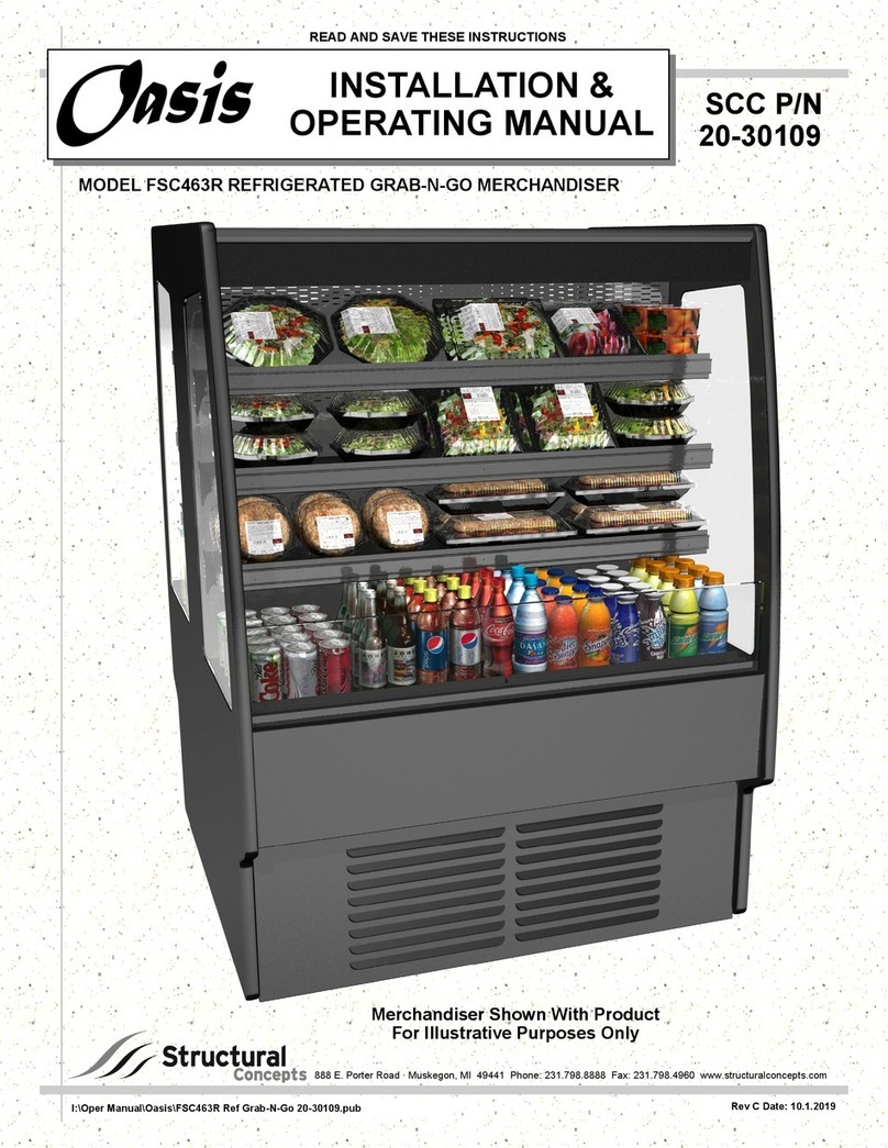
Model FSC463R Merchandiser Shown With Product
For Illustrative Purposes Only / This Unit is Similar to FSC663R
MODEL FSC463R & FSC663R REFRIGERATED GRAB-N-GO MERCHANDISER
SCC P/N
20-30109
Oasis
READ AND SAVE THESE INSTRUCTIONS
® USER
MANUAL
Structural Concepts Corp. ∙ 888 E. Porter Rd ∙ Muskegon, MI 49441 Phone: 231.798.8888 Fax: 231.798.4960 ∙ www.structuralconcepts.com

2
TABLE OF CONTENTS
OVERVIEW / TYPE / COMPLIANCE / WARNINGS / PRECAUTIONS / WIRING DIAGRAM ..............
REMOVAL OF CASE FROM SKID / POSITIONING UNIT ..…………..…………………………………..
ADJUSTING LEVELERS ………………………………………………...………………………………...….
FIELD WIRING BOX / ACCESS / PANEL REMOVAL / MAIN POWER SWITCH / TEMP. CONTROL
CEILING ORIGINATED ELECTRICAL & REFRIGERATION LINES / KNOCKOUT REMOVAL /
SEALING ……………………………………………………………………………………………….
MODEL FSC463R PLAN-O-GRAM (LOAD LEVEL GUIDELINES) ..…………………………………….
DIGITAL THERMOMETERS / SECURITY COVER INSTALLATION & REMOVAL …………..…..…...
POWER-UP CHECK (EVAPORATOR FAN AREA) ...……………………………………………………..
MAINTENANCE FUNDAMENTALS: NON-ADJUSTABLE SHELF / BRACKET ASSEMBLY ...…….
MAINTENANCE FUNDAMENTALS, CONTINUED: LED LIGHT FIXTURES / REMOVAL /
REPLACEMENT ………………………………………………………………………………...……..
REFRIGERATION FUNDAMENTALS: UNDERSIDE LAYOUT (BOTH SELF-CONTAINED &
REMOTE) ……………………………………………………………………………………………….
REFRIGERATION FUNDAMENTALS: SELF-CONTAINED UNIT ILLUSTRATED PARTS
BREAKDOWN ………………………………………………………………………………………….
GENERAL CLEANING (TO BE PERFORMED BY STORE PERSONNEL) - EXTERIOR / INTERIOR
GENERAL CLEANING (TO BE PERFORMED BY TRAINED SERVICE PROVIDERS ONLY) …..….
TROUBLESHOOTING (TO BE PERFORMED BY STORE PERSONNEL UNLESS STATED
OTHERWISE) …………………………………………………………………………………………..
TROUBLESHOOTING (TO BE PERFORMED BY TRAINED SERVICE PROVIDERS ONLY) ……….
TROUBLESHOOTING (BY TRAINED SERVICE PROVIDERS ONLY) - CONDENSING SYSTEM
TROUBLESHOOTING (BY TRAINED SERVICE PROVIDERS ONLY) - EVAPORATOR SYSTEM
PREVENTIVE MAINTENANCE (TO BE PERFORMED BY TRAINED SERVICE PROVIDERS) …….
PREVENTIVE MAINTENANCE: HONEYCOMB AIR DIFFUSERS (TO BE PERFORMED BY
TRAINED SERVICE PROVIDERS ONLY) .………………………………………………………...
SERIAL LABEL LOCATION & INFORMATION LISTED / TECH INFO & SERVICE………………......
CAREL® CONTROLLER - PROGRAMMING THE INSTRUMENT….……………………...….…….......
CAREL® CONTROLLER - USER INTERFACE, SUMMARY TABLES OF ALARMS & SIGNALS ….
CAREL® CONTROLLER - Summary Table of Operating Parameters (After Programming Key) .
TECHNICAL SERVICE CONTACT INFORMATION & WARRANTY INFORMATION ..…………….....
3-4
5
6
7
8
9
10
11
12
13
14
15
16
17
18
19-20
21
22
23
24
25
26
27
28
29

3
OVERVIEW
These Structural Concepts merchandisers are
designed to merchandise packaged products at 41 °F
(5 °C) or less product temperatures.
Cases should be installed and operated according to
this operating manual’s instructions to ensure proper
performance. Improper use will void warranty.
TYPE 1 vs. TYPE 2 CONDITIONS
This unit is designed for the display of products in ambient
store conditions where temperatures and humidity are
maintained within a specific range.
Self-Contained cases are designed for Type 1
conditions: Ambient conditions at 55% maximum
humidity and maximum temperatures of 75 °F (24 °C).
Remote cases are designed for Type 2 conditions:
Ambient conditions at 60% maximum humidity and
maximum temperatures of 80 °F (27 °C).
If unsure if your case is designed for Type 1 or Type 2
conditions, see identifier label on your case. Location
may vary.
COMPLIANCE
Performance issues when in violation of applicable
NEC, federal, state and local electrical and plumbing
codes are not covered by warranty. See below.
WARNINGS
This sheet contains important warnings to prevent
injury or death. Please read carefully!
PRECAUTIONS, MAINTENANCE & WIRING DIAGRAM
INFORMATION
See next page for PRECAUTIONS, MAINTENANCE
and WIRING DIAGRAM information.
WARNING
Hazardous moving parts. Do not operate unit with covers removed.
Fan blades may be exposed when deck panel is removed.
Disconnect power before removing deck panel.
WARNING
Risk of electric shock. Disconnect power before servicing unit.
CAUTION! More than one source of electrical supply is
employed with units that have separate circuits.
Disconnect ALL ELECTRICAL SOURCES before servicing.
WARNING
ELECTRICAL
HAZARD
WARNING
KEEP
HANDS
COMPLIANCE
This equipment MUST be installed in compliance with
all applicable NEC, federal, state and local
electrical and plumbing codes.
OVERVIEW / TYPE / COMPLIANCE / WARNINGS / PRECAUTIONS / WIRING DIAGRAM - PAGE 1 of 2
WARNING! POWER CORD AND PLUG MAINTENANCE
Risk of electric shock. If cord or plug becomes damaged,
replace only with cord and plug of same type.
WARNING: This product can expose you to chemicals, including
Urethane (Ethyl Carbamate), which are known to the state of
California to cause cancer and birth defects or other reproductive
harm. For more information go to P65Warnings.ca.gov.

4
OVERVIEW / TYPE / COMPLIANCE / WARNINGS / PRECAUTIONS / WIRING DIAGRAM - PAGE 2 of 2
CAUTION! GFCI BREAKER USE REQUIREMENT
If N.E.C. (National Electric Code) or your local code
requires GFCI (Ground Fault Circuit Interrupter) protection,
you MUST use a GFCI breaker in lieu of a GFCI receptacle.
CAUTION! LED LAMP REPLACEMENT GUIDELINES
LED lamps reflect specific size, shape and overall design.
Any replacements must meet factory specifications.
CAUTION
PRECAUTIONS
This sheet contains important precautions to prevent
damage to unit or merchandise. Please read carefully!
WIRING DIAGRAM
Each case has its own wiring diagram folded and in its
own packet.
Wiring diagram placement may vary; it may be placed
near ballast box, field wiring box, raceway cover, or
other related location.
REFRIGERANT DISCLOSURE STATEMENT
This equipment is prohibited from use in California with
any refrigerants on the “List of Prohibited Substances”
for that specific end-use, in accordance with California
Code of Regulations, title 17, section 95374.
This disclosure statement has been reviewed and
approved by Structural Concepts and Structural
Concepts attests, under penalty of perjury, that these
statements are true and accurate.
CAUTION! ADVERSE CONDITIONS / SPACING ISSUES
Performance issues caused by adverse conditions are NOT warranted.
To prevent damage to end panels due to condensation, apply industrial grade
silicone sealant and tightly join to opposite end panels. When not adjoining
cases, keep end panels at least 6” away from walls and structures. Rear
panels must also be kept at least 6” from walls and structures.
Case must not be exposed to direct sunlight or any heat source.
To maintain proper case temperature, keep case at least 15-feet from exterior
doors, overhead HVAC vents or any air curtain disruption.
Self-contained case clearance: 6” min. air intake / 6” min. air discharge.
CAUTION
CAUTION! CHECK CONDENSATE PAN, ITS POSITION & PLUG!
Water on flooring can cause extensive damage!
Before powering up case, check that condensate pan is positioned
directly under case’s condensate drain.
Before powering up case, check that condensate pan’s electrical plug is
SECURELY connected to condensate system’s receptacle.
If wicking material is used in condensate pan, check that it is secure.
CAUTION! DO NOT RELY ON THERMOMETERS OR
THERMOSTATS FOR PRODUCT (FOOD) TEMPERATURES.
Thermometers & thermostats reflect air temperatures ONLY.
For ACTUAL product (food) temperatures, use a calibrated food
probe thermometers ONLY.
For accurate readings, DO NOT use infrared food thermometers.

1. Remove Unit From Skid
For your safety, the equipment is furnished with
a properly grounded cord connector. Do not
attempt to defeat the grounded connector.
Caution! Remove BOTH lower panels from
case before removing from skid to prevent
buckling.
Illustrations below show case being removed
from skid.
REMOVAL OF CASE FROM SKID / POSITIONING UNIT
5
Place case in proper location.
Plug cord into certified electrical outlet with ground.
2. Positioning Unit
Place unit into desired location before leveling.
See next page for specifics about leveling.
Slide Skid Out
From Under
Case

ADJUSTING LEVELERS
6
Adjust Levelers
After case is in position, adjust case so it is level
and plumb.
You may need to remove front and/or rear
toe-kick to access levelers.
Use adjustable wrench (and/or a pry bar) to adjust
leveler.
Do not use Pry Bar on Toe-Kick as it will buckle.
Do not use Pry Bar on End Panel. It may chip.
Use Pry Bar ONLY on Base Frame to avoid
damaging case.
Pry Bar

7
FIELD WIRING BOX / ACCESS / PANEL REMOVAL / MAIN POWER SWITCH / TEMP. CONTROL
1. Field Wiring Box / Access
Warning! Turn power off and/or disconnect
power before providing maintenance and
service to unit.
Assembly/disassembly/servicing to be
performed by licensed electrical contractor.
Panel must be removed to access field wiring box
and main power switch.
See illustration below.
2. Panel Removal
To remove panel (and access field wiring box), lift
panel up and off case hooks by grasping firmly
and pulling up and outward.
See illustration at top-right.
Field Wiring /
Ballast Box
Thermostat Controller &
Main Power Switch
Main Power
Switch
3. Main Power Switch
For self-contained cases, the main power switch
controls power to entire case.
If main power switch is not turned on, lights will
not turn on NOR will refrigeration components
operate.
See illustration below.
4. Temperature Control
Illustration below shows location of temperature
controller (after removal of front panel).
See Carel Temperature Controller information
in this manual for specifics on settings.
Self-Contained Merchandiser
(Partially Disassembled)
Slots For Attaching
To Case Hooks
Removable Front Panel

8
CEILING ORIGINATED ELECTRICAL & REFRIGERATION LINES / KNOCKOUT REMOVAL / SEALING
1. Merchandiser Versatility
Structural Concepts cases can accompany
either floor or ceiling-originated electrical and/or
refrigeration lines.
This page shows how ceiling-originated lines
are routed into case.
2. Ceiling Routed Electrical/Refrigeration. Lines
A center pass-through protective plate is mount-
ed at top of case over two (2) PVC center
pass-throughs.
If electrical/refrigeration lines are ceiling-
originated, remove plate knockouts.
Electrical and/or refrigeration lines may then be
dropped through PVC center pass-throughs.
Caution! If ceiling-originated lines are used,
you MUST seal both upper and lower PVC
Center Pass-Through
Protective Plate Shown After
Removal of Knock-Outs
center pass-throughs (at entrance points) with
expandable foam sealant to prevent
condensation in case.
3. Plate Removal
Note: Though not required, protective plate can be
removed from merchandiser via four (4) screws.
4. Case Underside
See REFRIGERATION FUNDAMENTALS:
UNDERSIDE LAYOUT (BOTH
SELF-CONTAINED & REMOTE) section in this
manual for location of center pass-throughs at
underside of case.
Center Pass-Through Protective
Plate Mounted on Merchandiser
Caution! If ceiling originated lines are
used, you MUST seal both upper and
lower PVC center pass-throughs (at
entrance points) with expandable
foam sealant to prevent
condensation in case.

9
MODEL FSC463R & FSC663R PLAN-O-GRAM (LOAD LEVEL GUIDELINES)
CAUTION! TO MAINTAIN SAFE PRODUCT TEMPERATURES AND AIRFLOW
CAREFULLY FOLLOW THESE GUIDELINES:
DO NOT STACK PRODUCT NEARER THAN 1” TO UNDERSIDE OF PLENUM
DO NOT STACK PRODUCT NEARER THAN 1” TO UNDERSIDE OF SHELVES
DO NOT ALLOW PRODUCT TO HANG OVER FRONT OF SHELVES
DO NOT STACK PRODUCT ON DECKS HIGHER THAN UNDERSIDE OF SHELF
DO NOT ALLOW PRODUCT ON DECKS TO HANG OVER PRODUCT STOP
ACCEPTABLE
PRODUCT PLACEMENT
1” Min.
--- SIDE VIEW --- --- SIDE VIEW ---
Do Not Allow Product
On Decks To Hang
Over Product Stop
Do Not Stack Product
Nearer Than 1” To
Underside of Plenum
Do Not Stack Product On
Decks Higher Than The
Underside Of Lower Shelf
Do Not Stack Product
Nearer Than 1” To
Underside of Shelves
Do Not Allow Product
To Hang Over Front
of Shelves
Acrylic Air
Deflector
1” Min.
1” Min.
1” Min.
Product
Stop
SCC P/N 20-30299
NOTE: ANY
REVISIONS TO THIS
DOCUMENT MUST
ALSO BE MADE TO
SCC P/N 20-30299
UNACCEPTABLE
PRODUCT PLACEMENT
Model FSC463R and FSC663R Plan-O-Gram (Load Level Guidelines)
> Note: Any changes to this document must also be made to SCC User Manual P/N 20-30109.

DIGITAL THERMOMETERS / SECURITY COVER INSTALLATION & REMOVAL
10
1. Digital Thermometers
Digital thermometers are located on rear plenum at
upper area of case.
Digital thermometers are on BOTH side of case.
See enlarged illustration at lower-left.
2. Security Cover Installation (Optional)
A. Place security cover inside lower retainer brack-
et. See illustration of random unit with lower
retainer bracket at below-right.
B. Lean security cover against header at top of unit.
C. With key inserted in the lock, rotate the locking
mechanism’s “flat bar” into the bracket with slot at
center of case. See illustration at top-right and
mid-right.
3. Security Cover Removal (Optional)
A. With key inserted in the lock, rotate the locking
mechanism’s “flat bar” out of the bracket with slot
(as shown in top-right illustration).
Digital
Thermometer
B. Lean security cover away from header at top of
unit.
C. Holding security cover handles (or grasping sides
of security cover, if no handles), lift security cover
up and away from header. See illustration
below-right
Security
Cover
Key & Locking
Mechanism
Locking
Mechanism With
“Flat Bar” To
Lock Into Slot
Bracket
With Slot
For Latch
Sample View of
Lower Retainer
Bracket (Rotated
For Illustrative
Purposes Only)
Header

POWER-UP CHECK (EVAPORATOR FAN AREA)
11
Power-Up Check (Evaporator Fan Area) On Both Sides of Merchandiser
After power has been supplied, evaporator coil fans will be operational.
To verify fans are operational, lift up deck pans; check to see that the coil fans are functioning properly.
See illustration below (partially disassembled for illustrative purposes only).
Evaporator Coil
Fans
Illustration Shown May Not
Exactly Reflect Every
Feature or Option of Your
Particular Case
TXV DrainRefrigeration
Lines Route

12
MAINTENANCE FUNDAMENTALS: NON-ADJUSTABLE SHELF / BRACKET ASSEMBLY
1. Airflow/Temperature Requirements
This merchandiser is tested in the factory to
maintain airflow and temperatures in a very
narrow range.
The positioning of each shelf/bracket assemblies
in its specific slot is crucial to maintaining this
factory set temperature and airflow.
2. Shelf / Bracket Assembly
Shelf/bracket assemblies ARE NOT to be
adjusted or moved from their factory determined
slots.
Item 3 below provides an exception to this
guideline.
3. Shelf / Bracket Assembly Removal
Cleaning can usually be accomplished
WITHOUT the removal of the shelf/bracket
assembly.
Should stubborn stains or residue require removal
of shelf/bracket assembly however, see
GENERAL CLEANING (TO BE PERFORMED
BY STORE PERSONNEL) - EXTERIOR /
INTERIOR section in this manual for specifics.

2
13
MAINTENANCE FUNDAMENTALS, CONTINUED: LED LIGHT FIXTURES / REMOVAL / REPLACEMENT
1. LED Light Switch
LED light switch to entire case is always located
in upper section of the case.
See illustration below.
2. LED Light Fixtures
Light fixtures are located in upper section of the
case (in front of honeycomb) and under
shelving.
3. LED Light Fixture Removal and
Replacement
This case is provided with mini-LED lights which
will rarely require change-out.
To remove LED light fixture, disconnect the
existing LED light from its brackets. Replace.
Note: LED Plug must be connected in a specific
manner or they will not work.
Oval form of plug must connect to oval form of
LED light. See illustrations at top-right.

14
REFRIGERATION FUNDAMENTALS: UNDERSIDE LAYOUT (BOTH SELF-CONTAINED & REMOTE)
Self-Contained & Remote Refrigeration Line Access, Connections & Servicing To Be
Accomplished By Licensed Contractors Only
Partially-disassembled illustration below shows location of refrigeration lines for self-contained operation.
Two (2) drains accessible from top of unit by lifting up decking.
See POWER-UP CHECK (EVAPORATOR FAN AREA) section in this manual for under decking drain
illustration.
Case Rear
Drain
Drain Line (To Position
Over Condensate Pan)
Refrigeration
Lines
Case Front
Drain
Electrical
Box
Center Pass-Through
(Covered)
Drain Line (To Position Over Condensate
Pan or Route To Floor Drain)

15
REFRIGERATION FUNDAMENTALS: SELF-CONTAINED UNIT ILLUSTRATED PARTS BREAKDOWN
Refrigeration
U-Tubes
Filter Dryer
Electrical
Starter Unit
Condenser Coil Housing
Condenser Coil Fan,
Fan Housing & Motor
Refrigeration
Lines
Sight Glass
Compressor
Pan
Self-Contained Merchandiser’s Condensate Unit Illustrated Parts Breakdown
Assembly/disassembly and servicing to be performed by licensed refrigeration contractor.

GENERAL CLEANING (TO BE PERFORMED BY STORE PERSONNEL) - EXTERIOR / INTERIOR
16
FREQ. AREA / INSTRUCTIONS
Daily Deck/Rear Plenums: Clean with a warm soap and water solution. For stubborn stains and
residue, TURN MAIN POWER SWITCH OFF. Remove deck and clean with soap and water
solution or submersed in hot, soapy water solution. Rinse thoroughly. Dry. Return to case.
Turn main power switch back on.
Daily Glass Surfaces (Sides): Clean with household or commercial glass cleaner.
Weekly Shelving/Bracket Assemblies
Wipe off shelf/bracket assemblies with moist cloth.
Brackets and shelving CAN BE removed for more thorough cleaning. Caution! Removal
of shelving/bracket assemblies should ONLY be performed when stubborn stains or
residue CANNOT be removed with shelving/bracket assemblies remaining on case.
To remove shelf/bracket assembly, simply lift upward and out.
Caution: As LED lighting is attached to underside of shelving, you must disconnect LED
wire from its connectors. Due to the electrical components, DO NOT submerse shelving/
bracket assemblies while cleaning.
Clean with mild soap and water solution and a non-abrasive soft cloth. For stubborn
stains use a nylon brush. DO NOT use abrasive cleaners or Brillo® pads, as these can
destroy the shelf/bracket finish.
Caution! After removing and cleaning shelving/bracket assemblies YOU MUST return
them to THE SAME EXACT slots they were in prior to their removal.
Reconnect connectors into LED plugs after shelving/bracket assemblies are in place.
Weekly Side Panels All Around (and Upper Fascia): Clean with mild soap and water solution and a
non-abrasive soft cloth.
Weekly Acrylic Air Deflectors: Clean with warm water, mild soap solution and soft cloth; acrylic
cleaning solutions are also available. Caution! Never use ammonia-based cleaners on
acrylic. Incorrect cleaning agents or abrasive cleaning cloths cause surface to ‘cloud’ over
time.
Weekly Condenser Coil: Vacuum or brush grille condenser coil at case front. Use metal or fiber
brush to remove dust and dirt that can collect on condenser coils. Be careful not to damage
the fins on the coil. See REFRIGERATION FUNDAMENTALS: CONDENSATE PACKAGE
ACCESS section in this manual for instructions on side panel removal.
Monthly Under Case Cleaning: Remove front (or rear) panels. Vacuum under case to remove all dust
and dirt. Replace front (or rear) panels when complete.

GENERAL CLEANING (TO BE PERFORMED BY TRAINED SERVICE PROVIDERS ONLY)
17
AREA TO CLEAN FREQUENCY INSTRUCTIONS
Case Interior Monthly Evaporator Fan Shroud Area (Under Decking): Caution! Due to
rotating fans in area, turn off case and disconnect plug from wall
outlet before beginning fan shroud (and surrounding tub area)
cleaning! 1) Turn off power. 2) Remove deck from case. 3)
Clean fan shroud area (and surrounding tub area) with moist cloth.
Quarterly Tub & Drain: Caution! Due to rotating fans in area, turn off case
and disconnect plug from wall outlet before beginning tub & drain
cleaning! Vacuum tub under decks. Clean with soap and water
solution. Wipe dry with clean cloth. Keep drain free of debris to
prevent clogging.

TROUBLESHOOTING (TO BE PERFORMED BY STORE PERSONNEL UNLESS STATED OTHERWISE)
18
CONDITION TROUBLESHOOTING
Water Is On The Floor Floor drain units: Check that drain (at underside of case) is properly routed
to floor drain.
Call service provider.
Fans Emit Excessive Noise Call service provider.
No Case Lights Are
Working
Check that light switch is in the on position.
Check that ALL of the light cords and plugs are properly connected. See
MAINTENANCE FUNDAMENTALS - SHELF & BRACKET ASSEMBLY
REMOVAL / LIGHT FIXTURES section in this manual for specifics.
Authorized Service Contractors Only: Check circuit breaker box for
tripped circuit.
If case lights still do not come on, call service provider.
One (or Several) Case
Lights are Not Working
Check that ALL of the light cords and plugs are properly connected. This
includes the following items:
Oval form of plug must connect to oval form of LED light.
The power end of cord is to connect at the “red dot” marker at the end
of the LED lamp.
See MAINTENANCE FUNDAMENTALS - SHELF & BRACKET
ASSEMBLY REMOVAL / LIGHT FIXTURES section in this manual
for more specifics including illustrations.
If case light still do not come on, call service provider.
Case is Not Holding Proper
Temperature
If a large amount of warm product was added to the case, it will take time
for the temperature to adjust. Product must be pre-chilled before placing
in case.
Check that the case is not in the sun or near a heat or air-conditioning
vent. See OVERVIEW / TYPE / COMPLIANCE / WARNINGS /
PRECAUTIONS / WIRING DIAGRAM section in this manual for
specifics.
If case is located near front doors, temperature fluctuation can hinder
unit’s ability to maintain temperature. See OVERVIEW / TYPE /
COMPLIANCE / WARNINGS / PRECAUTIONS / WIRING DIAGRAM
section in this manual for specifics.
Check air return grilles (area at front of decking) for obstructions.
DO NOT set product on air grilles as this will prevent proper airflow!
If case still is not holding proper temperature, call service provider.

TROUBLESHOOTING (TO BE PERFORMED BY TRAINED SERVICE PROVIDERS ONLY)
19
CONDITION TROUBLESHOOTING
Water Is On The Floor Check that the drain trap is free of debris.
Check that the drain hose is correctly positioned over floor drain.
Remote units condensate pump: Check that unit is operating properly.
Check store conditions.
For Type 1 Conditions (most cases): ambient conditions are to be at 55%
max. humidity / 75°F.
For Type 2 Conditions: ambient conditions are to be at 60% maximum
humidity / 80°F.
Fans Emit Excessive
Noise
Check that the case is aligned, level and plumb.
Check evaporator fan for cleanliness.
Unplug/power off fan motors. Check motor shaft for bearing wear.
Check that fan motors are securely mounted in brackets.
Verify that fan blades are securely mounted to fan motor.
Check that nothing is preventing blade rotation.
Check that the fan shroud is properly secured.
Fans Are Not Working Check that the MAIN power switch is on.
Check that fans are plugged in at the fan shroud.
Check for foreign material obstructing fan performance.
Check that fan blades freely rotate within fan shrouds
Check that power is going to fans
Check that fan wiring is connected on terminal blocks.
Digital Control Display
Is Blank.
Check that the MAIN power switch is on.
Check the circuit breaker box for tripped circuits.
System Not Operating Check that the utility power is on.
Check that the MAIN power switch is on.
Check the circuit breaker box for tripped circuits.

TROUBLESHOOTING (TO BE PERFORMED BY TRAINED SERVICE PROVIDERS ONLY), CONTINUED
20
CONDITION TROUBLESHOOTING
No Case Lights Are
Working
Follow previous page’s System Not Operating instructions.
Check voltage at LED driver. If voltage is entering but not exiting, LED driver
may be faulty.
Check connection at front of case (from circuit breaker) for voltage.
Check connection at case rear (from field wiring box) for voltage.
If no case light STILL do not come on, call SCC Technical Service phone num-
ber (listed on last page of this operating manual).
One (or Several) Case
Lights are Not Working
Follow previous page’s System Not Operating instructions.
If case light still do not come on, call SCC Technical Service phone number
(listed on last page of this operating manual).
Control Display Is
Flashing
See your case’s serial label for your model’s specified settings. See SERIAL
LABEL LOCATION & INFORMATION LISTED / TECH INFO & SERVICE
for label location, etc.
Case Is Not Holding
Temperature
If a large amount of warm product was added to the case, it will take time for
the temperature to adjust. Unit needs product to be pre-chilled.
Temperature changes during defrost mode but will return to normal. Fourth
LED (on temperature controller) will indicate defrost cycle in progress.
Check that case is not in sun or near a heat or air-conditioning vent.
If case is located near front doors, temperature fluctuation can hinder unit’s
ability to maintain temperature.
Check air grilles for obstructions.
This manual suits for next models
1
Table of contents
Other Oasis Merchandiser manuals
Popular Merchandiser manuals by other brands

Delfield
Delfield Shelleyspeed SPHM-50EW Specifications

Hussmann
Hussmann IMPACT Elite E2 datasheet

Hoshizaki
Hoshizaki RM-10 instruction manual

Hoshizaki
Hoshizaki HNC-120BE-R-BLH Service manual

Howard McCray
Howard McCray R-OM30E-3L-LS Specifications

Polar Refrigeration
Polar Refrigeration CG841-A instruction manual

Hussmann
Hussmann SCSS Installation and operation guide

Bakers Pride
Bakers Pride PD-4 Specifications

Igloo
Igloo INNOVA series instruction manual

Structural Concepts
Structural Concepts Oasis MOT4048RSS.5197 Installation & operating manual

Hussmann
Hussmann impact Excel C2X-XLGE Technical data sheet

Summit
Summit Classic CL181WBV instruction manual