Observator Instruments ANALITE NEP-5000-LINK User manual

Manual | NEP-5000-LINK
Status: Final | Not confidential
Page 2 | 34
V20200304
Document history
The Observator range is in continuous development and so specifications may be subject to change
without prior notice. When in doubt about the accuracy of this document, contact the Observator Group.
Reference documents
Type of document / tool
Product type and name (incl. url)
Datasheet
NEP-5000-LINK
Manual
NEP-5000-LINK
Analite
application notes
Shroud installation
Wiper replacement
Revision history
Date
Amendments
Company, position
2016-11-12
Initial document creation
Observator Australia,
Document Controller
2017-07-31
Updated external links
Observator Australia,
Document Controller
2017-08-21
Updated battery accuracy
Observator Australia,
Document Controller
2017-10-24
Edited warranty conditions
Observator Australia,
Document Controller
2018-04-09
Introduced document control
Observator Australia,
Document Controller
2019-03-09
Added reference documents
Observator Australia,
Document Controller
2019-07-04
Quality review
Observator Australia,
Operation Manager
2019-08-14
Updated product design & charging operations
Observator Australia,
Document Controller
2019-08-26
Compressed images in document
Observator Australia,
Document Controller
2020-01-30
Updated document format
Observator Australia,
Document Controller
Procedure sign-off:
Date
Company, position
Status
2018-04-09
Observator Australia, Document Controller
Finished
2019-12-06
Observator Australia, Managing Director
Approved
2020-03-04
Observator Group, Communication Officer
Approved
Distribution list
Date
Company, position

Manual | NEP-5000-LINK
Status: Final | Not confidential
Page 3 | 34
V20200304
Summary
Thanks for purchasing the new Analite NEP-5000-LINK wireless handheld display and logging solution. It
will give you years of service if you install and maintain the turbidity monitoring system according to
guidelines as set out in this manual.
What is NEP-5000-LINK?
The NEP-5000-LINK handheld solution is comprised of an Analite NEP-5000 auto-ranging turbidity
sensor, a NEP-5000-LINK wireless interface and a NEP-LINK android application for your Bluetooth-
enabled Android device.
The Analite NEP-5000 auto-ranging/wiping ISO-7027 90° and/or backscatter 180° turbidity sensors set a
new industry standard for accuracy and stability across an unmatchable full-scale range.
The NEP-5000-LINK system can be ordered with a compact NEP-5000 90° for nephelometric field
measurements up to 5,000 NTU* or in a 180° version (backscatter optics) for sediment studies up to
30,000 NTU*. The NEP-5000-LINK compact NEP-5000 sensors have all the features of the top of the line
Analite NEP-5000 sensors but are purpose built to minimize power demand and cost.
The NEP-5000-LINK interface module provides rechargeable power to the sensor and manages wireless
communication to a Bluetooth enabled Android device. The module is lightweight, compact, and clips to a
belt for a hands-free experience.
The NEP-5000-LINK Android smartphone application has a large range of features that support data
visualization, data logging, and data management. Data can be viewed locally (on device) or exported in
excel format via Bluetooth, email or General Packet Radio Services (GPRS) to external data servers.
Logged data is time/date stamped and location tagged for mapping.
The NEP-5000-LINK system is a portable product that is ideal for industrial, field and laboratory
applications. This is a great reference tool for spot checking in-situ installations. The freedom to port data
directly to a phone, tablet or laptop offers the end user, field/lab work efficiencies and an ordered means of
managing data. NEP-5000-LINK can be customized and can be upgraded. The NEP-5000-LINK handheld
solution offers un-paralleled ease of use, accuracy, and a very competitive price.
(*) Note: See all sensor ranges and specifications. Please study the sensor datasheet.

Manual | NEP-5000-LINK
Status: Final | Not confidential
Page 4 | 34
V20200304
Table of contents
1Applications .................................................................................................................... 5
2Safety............................................................................................................................... 6
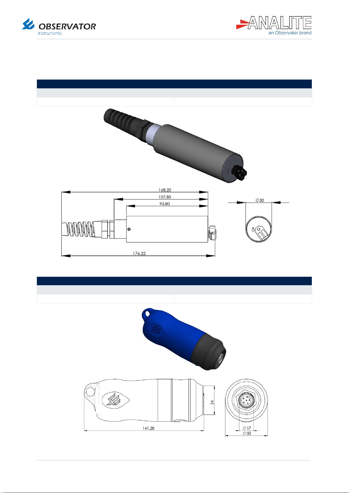
3Specification ................................................................................................................... 7
4Pinout & wiring diagram.................................................................................................9
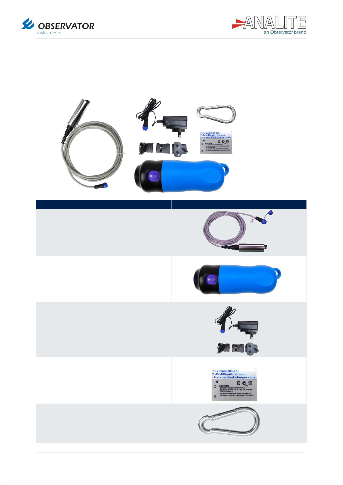
5What you will find in the box.........................................................................................10
6Accessories....................................................................................................................11
7Installation......................................................................................................................13
7.1 Install the sensor for the first time .....................................................................................................13
7.2 Charging the battery..........................................................................................................................15
8Android application interface........................................................................................16
8.1 Activate the Global Positioning System (GPS) location & Bluetooth ................................................16
8.2 Pair the sensor via Bluetooth ............................................................................................................17
8.3 Launch the app & connect to sensor.................................................................................................18
8.4 Record data.......................................................................................................................................19
8.5 Export data........................................................................................................................................20
8.6 View a record ....................................................................................................................................21
8.7 Comment a record.............................................................................................................................22
8.8 Turn off NEP-5000-LINK interface ....................................................................................................23
8.9 Quit the application............................................................................................................................23
8.10 Delete a record..................................................................................................................................24
8.11 Access additional information............................................................................................................25
8.12 Change sensor name........................................................................................................................25
8.13 Read the Bluetooth battery level.......................................................................................................26
8.14 Export in local folder..........................................................................................................................27
9Deployment ....................................................................................................................28
9.1 Deploy the sensor .............................................................................................................................28
9.2 Take proper measurements..............................................................................................................30
9.3 Retrieve the sensor ...........................................................................................................................30
10 Maintenance & calibration.............................................................................................31
10.1 Battery replacement..........................................................................................................................31
10.2 Cleaning the sensor ..........................................................................................................................32
10.3 Calibration .........................................................................................................................................33
10.4 Long-term storage.............................................................................................................................33

Manual | NEP-5000-LINK
Status: Final | Not confidential
Page 5 | 34
V20200304
1 Applications
Typical use of the NEP-5000-LINK device include applications such as:
1. Monitoring of streams and rivers
2. Monitoring of water storage bodies including stratification studies
3. Intermediate and final effluent treatment monitoring
4. Hydrological run off studies
5. Ground and bore water analysis
6. Drinking water filtration efficiency
7. Industrial process monitoring
8. Sludge and dredge monitoring
9. Sediment load monitoring
The NEP-5000-LINK products are also ideal for water quality, food processing, waste treatment and
environmental compliance for dredging operations.

Manual | NEP-5000-LINK
Status: Final | Not confidential
Page 6 | 34
V20200304
2 Safety
Do not connect anything that is potentially electrical to the metal body of the sensor. If
you do, it may result in electrical shocks that could harm you or destroy your
instruments.
Do not attempt to force the wiper mechanism while operating or you may harm yourself
due to the higher torque level.
Please check with your supplier or material specifications before using the sensor in
unknown chemical.
Take appropriate precaution when handling or servicing pre-deployed sensors otherwise
you may be exposed to radioactive and hazardous solutions.
After end of life of this product, dispose it according to your local regulations or return it
to the manufacturer.

Manual | NEP-5000-LINK
Status: Final | Not confidential
Page 7 | 34
V20200304
3 Specification
NEP-5000-LINK sensor dimensions
Length
177mm
Diameter
30mm
NEP-5000-LINK wireless module dimensions
Length
141mm
Diameter
50mm

Manual | NEP-5000-LINK
Status: Final | Not confidential
Page 8 | 34
V20200304
Connectivity
NEP-5000-LINK interface (Bluetooth module)
Scalable Parallel Processor (SPP) profile
NEP-5000 Transistor–Transistor Logic (TTL)
(streaming)
(not polled)
Power supply
Rechargeable Lithium Ion battery
(CAN.NB-10L)
450mAh –7.4V
(Battery life ~6 hours of operation)
Power supply, charge through 7.4V power pack, powers on when sensor is plugged in
Auto power off when battery is less than 20%
Long press power off
Android application
Turbidity, range reading & recording
Log files have embedded location, time & date, comments and photos
Logging of comma delimited data sentence
Statistic and smart graph viewer tool
Fast data export
Battery status and charge indicator
Sensor status and wiping indicator
Sensor
Auto-ranging from sensors 3 ranges
Range 1 --- 0 to 40NTU
Range 2 --- 0 to 400NTU
Range 3 --- 0 to 5,000NTU
Accuracy
±1% Full Scale Output (FSO) at 25˚C all ranges
(90° version)
Auto wipe
On interval specified by user and
power on wipe
Compatibility
Android application for smartphone
Version 6.0 & above
Windows tablet
Available upon request
Capabilities
Turbidity
(From sensor)
Temperature
(From sensor)
Location

Manual | NEP-5000-LINK
Status: Final | Not confidential
Page 9 | 34
V20200304
4 Pinout & wiring diagram
The Pinout configuration of the NEP-5000-LINK is the following:
Pin number
Meaning
#1
Ground (GND)
#2
(Spare)
#3
Transistor–Transistor Logic (TTL) Comms
#4
Volt VAR Control (VCC)-sensor
#5
Charge
#6
(Spare)

Manual | NEP-5000-LINK
Status: Final | Not confidential
Page 10 | 34
V20200304
5 What you will find in the box
When the product is delivered, this is what you will find in the box:
Items found in the box
90° turbidity sensor
NEP-LINK-TURB
NEP-5000-LINK interface module
NEP-LINK-BTM
Charging cable
NEP-LINK-CHARGE
Standard Li-Ion battery
NEP-LINK-BAT
NEP-5000-LINK interface module hook
NEP-LINK-HOOK

Manual | NEP-5000-LINK
Status: Final | Not confidential
Page 11 | 34
V20200304
6 Accessories
Observator Instruments offers a wide range of accessories for the NEP-
5000-LINK range. These products are available directly from the website.
Accessories
Spare turbidity sensor (can be a replacement 90°
or optional 180° backscatter)
NEP-LINK-TURB
Spare charging adapter
NEP-LINK-CHARGE
Spare standard Li-ion batteries
(up to 5 hours recording)
NEP-LINK-BAT
NEP-LINK-CASE
Calibration module
(blue box) for calibrating the sensor
NEP-LINK-CFG

Manual | NEP-5000-LINK
Status: Final | Not confidential
Page 12 | 34
V20200304
Accessories
Wiper replacement kit
NEP-WIPER-KIT
Spare NEP-5000-LINK interface module
NEP-LINK-BTM
Shroud
NEP-SHRD-D
NEP-5000-LINK interface module hook
NEP-LINK-HOOK
Calibration solutions
NEP-CAL-GFS
Brown bottle for calibration
NEP-CAL-BTL

Manual | NEP-5000-LINK
Status: Final | Not confidential
Page 13 | 34
V20200304
7 Installation
7.1 Install the sensor for the first time
Connect the Li-Ion battery to the NEP-5000-LINK interface module (normally installed when provided). If it
is not, please follow the instruction described in chapter 10. Section 10.1: “Battery replacement”.
To install the Android application on your smartphone, use the following link, download and install the
“.apk file” (for smartphone).
1. Remove the protective caps and connect NEP-5000-LINK sensor to the NEP-5000-LINK interface
module.
Figure 7.A: Download & install NEP-LINK application

Manual | NEP-5000-LINK
Status: Final | Not confidential
Page 14 | 34
V20200304
Press on the NEP-5000-LINK interface module button and you will notice the blue Light-Emitting Diode
(LED) indicator turning on. If you cannot see the blue indicator light, it means the NEP-5000-LINK
interface module is not powered.
Light-Emitting Diode (LED)
status
Colour
Meaning
Flashing blue
Bluetooth available for pairing
Flashing green
Device is paired and connected
Flashing red, blue & green
Battery is charging or charged
No LED
NEP-5000-LINK interface module off
2. Run the app: go to the Chapter 8: “Android application interface”of this document.
Note: In the event where the indicator is not lighting up, ensure that the NEP-5000-LINK interface
module has enough battery (refer to the Section 10.1: “Battery replacement” of this manual) and
ensure that the long term storage switch inside the Bluetooth module is on.
Note: If storing the wireless interface for more than six months, please power off the device.
Long-term
storage switch
is on
Blue LED is on

Manual | NEP-5000-LINK
Status: Final | Not confidential
Page 15 | 34
V20200304
7.2 Charging the battery
1. Connect the provided charging adapter to the NEP-5000-LINK interface module and apply power.
2. At any time, you can monitor the charging status of the module by pressing on the NEP-5000-LINK
interface button. The LED indicator is flashing green, blue and red to indicate that the battery is
charging.
3. We highly recommend to use the application to monitor the battery level, please refer to chapter 8,
Section 8.13: “Read the Bluetooth battery level”.
4. When battery is fully charged, disconnect the charging cable and screw the protective cap back on.
Note: The best way to verify if the battery is fully charged is to use the Android Application to monitor
the battery level. The user should expect that the charge will take up to three hours of charging from
fully flat battery.

Manual | NEP-5000-LINK
Status: Final | Not confidential
Page 16 | 34
V20200304
8 Android application interface
8.1 Activate the Global Positioning System (GPS) location & Bluetooth
1. Go to your phone options.
2. Activate the GPS location of your phone.
3. Activate Bluetooth.

Manual | NEP-5000-LINK
Status: Final | Not confidential
Page 17 | 34
V20200304
8.2 Pair the sensor via Bluetooth
After having activated the Bluetooth of your
phone:
1. Turn on the NEP-5000-LINK interface by
pressing on the blue button, make sure that the
blue LED indicator turns on.
2. Go to the Bluetooth settings, scan to find the
new device. Select the new sensor to pair and
press pair.
3. Wait while pairing the sensor.
4. Allow pairing by pressing “Ok”.
5. Sensor is now shown as paired, you can now
run NEP-LINK application.
Blue indicator is
flashing
Note: Step 2 to 5 are to be completed only the first
time you connect to a new sensor.

Manual | NEP-5000-LINK
Status: Final | Not confidential
Page 18 | 34
V20200304
8.3 Launch the app & connect to sensor
1. Search for “NEP-LINK” application in Google Play store or
alternatively scan the Quick Response Code (QR) code
below. Download and open the software.
2. Wait for the app to load.
3. Search for device to connect to by pressing on “Find
Device”. If you cannot see the device, make sure that the
NEP-5000-LINK interface module is available and the blue
LED is on.
4. Select device from the available list. You will notice the
LED indicator turns green when app is successfully
connected to the module.
Note: If you want to turn off the module, make sure you
disconnect the wireless module from the application.
Green indicator is
flashing

Manual | NEP-5000-LINK
Status: Final | Not confidential
Page 19 | 34
V20200304
8.4 Record data
1. When connecting to the sensor for the first time, wait a few seconds in order to load the data.
2. Press on “Start logging to start the record”. If a “Wiping” message appears on the screen it means that
the sensor is wiping and not taking further measurements.
3. Press “Stop record” when required.
4. If the user did not take a picture, the app will offer the user to record a picture on the database, press
“Ok”.
5. Take a picture.
6. Press “Save” to save the picture in the database, alternatively press “Discard” to take another picture.

Manual | NEP-5000-LINK
Status: Final | Not confidential
Page 20 | 34
V20200304
8.5 Export data
1. Go to the menu page by clicking on the left-hand side Icon.
2. Select “Logged Data” menu.
3. “Logged Data” menu will display the records available from the most recent to the oldest, click on the
icon of the selected record to display options.
4. Select export option.
5. Select your export method.
6. Compose your email including the recipient and click on the send button to send the log file and the
pictures attached.
Table of contents
Other Observator Instruments Accessories manuals