IFM PI2798 User manual

Operating instructions
Electronic pressure sensor
PI27xx
704924/00 01/2011
UK

2
Contents
1 Preliminary note���������������������������������������������������������������������������������������������������4
1�1 Symbols used ������������������������������������������������������������������������������������������������4
2 Safety instructions �����������������������������������������������������������������������������������������������4
3 Functions and features ����������������������������������������������������������������������������������������5
3�1 Applications ���������������������������������������������������������������������������������������������������5
4 Function���������������������������������������������������������������������������������������������������������������5
4�1 Operating modes �������������������������������������������������������������������������������������������6
4�1�1 2-wire operation������������������������������������������������������������������������������������6
4�1�2 3-wire operation������������������������������������������������������������������������������������6
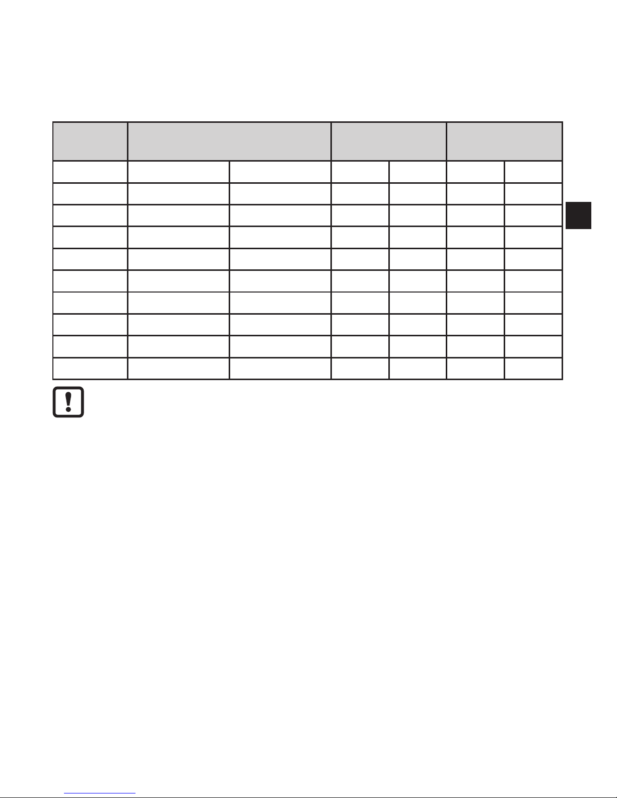
4�2 Switching function (only for 3-wire operation)������������������������������������������������6
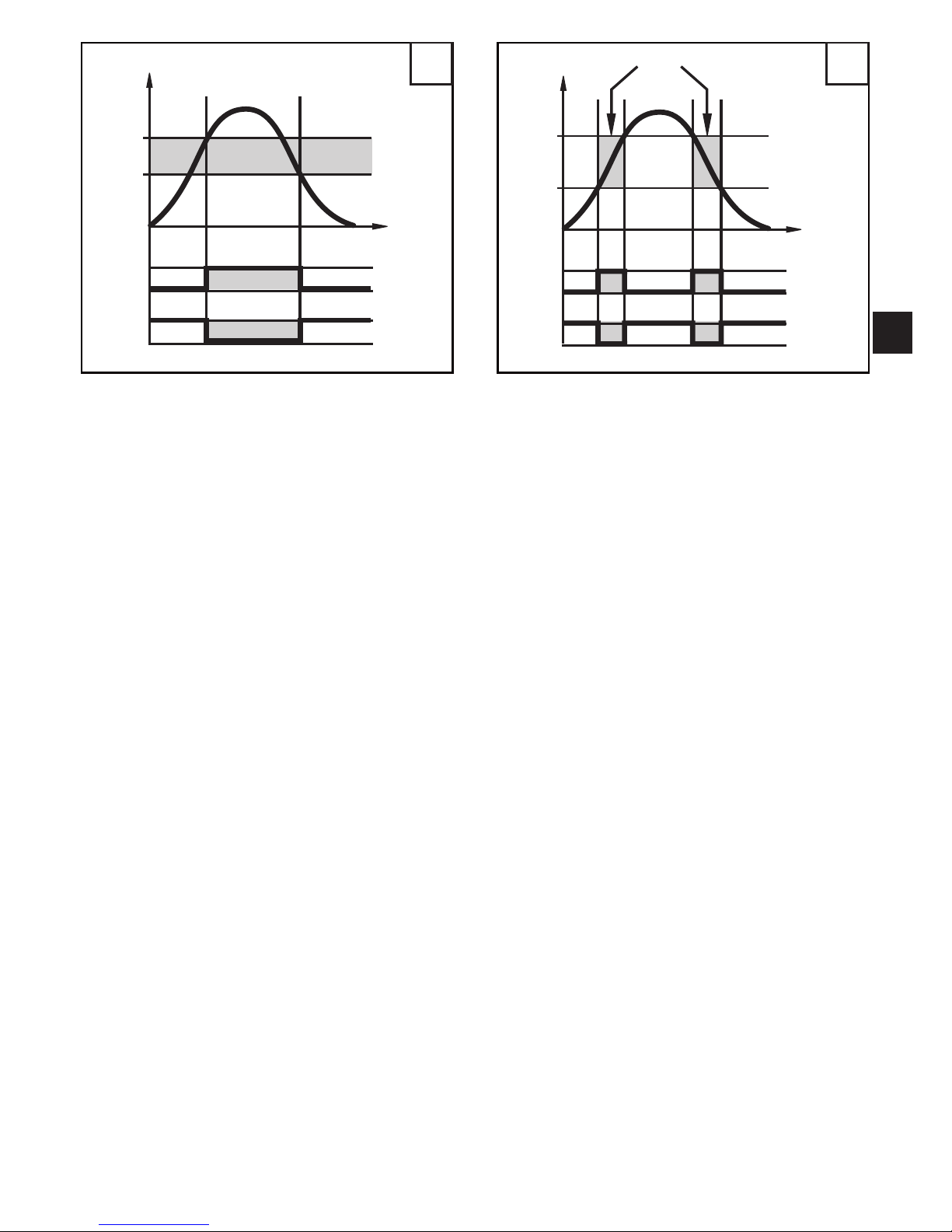
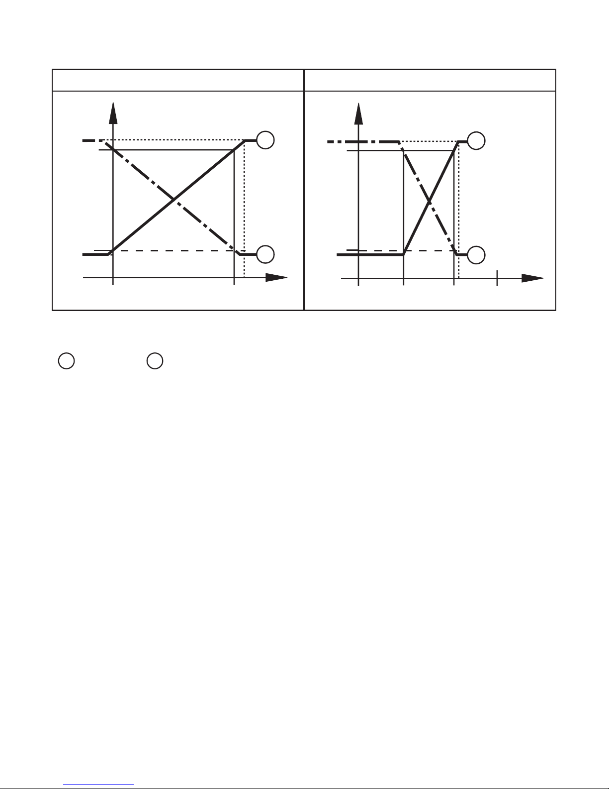
4�3 Analogue function ������������������������������������������������������������������������������������������7
4�4 Customer-specific calibration ������������������������������������������������������������������������9
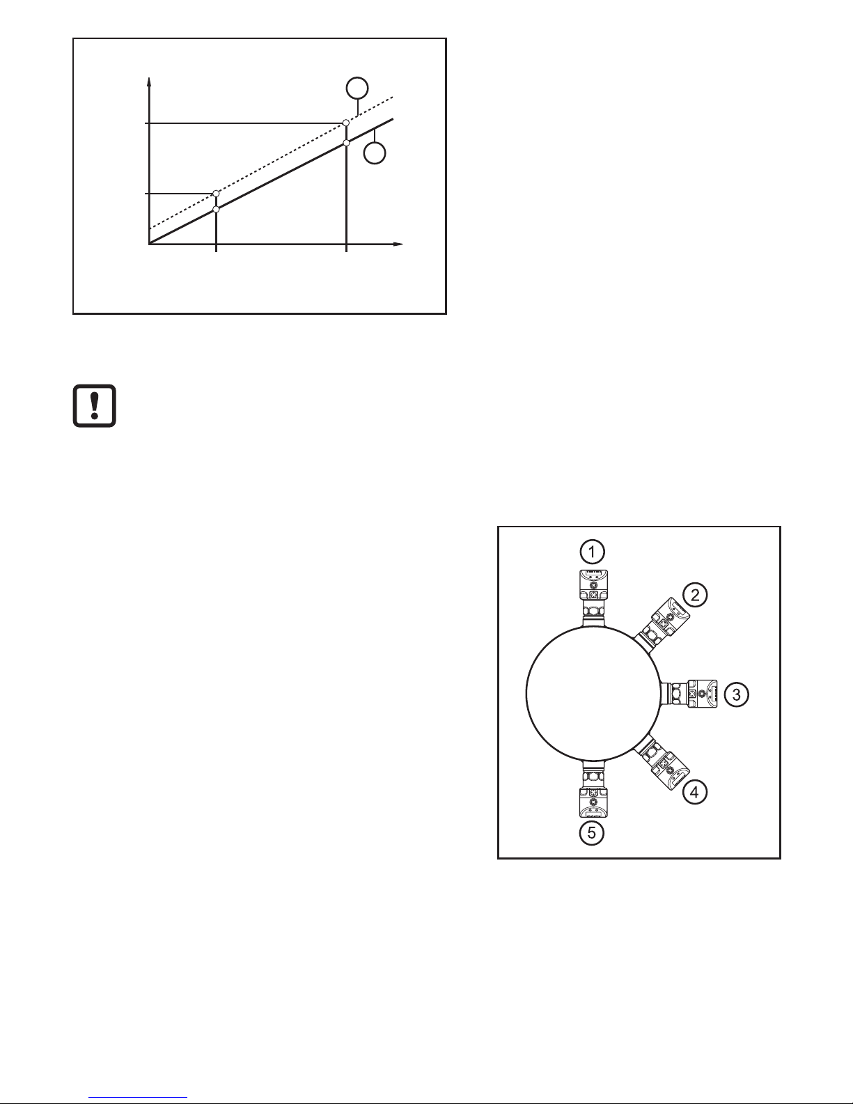
5 Installation����������������������������������������������������������������������������������������������������������10
6 Electrical connection������������������������������������������������������������������������������������������ 11
6�1 Connection for 2-wire operation ������������������������������������������������������������������ 11
6�2 Connection for IO-Link parameter setting����������������������������������������������������12
6�3 Connection for 3-wire operation ������������������������������������������������������������������12
7 Operating and display elements ������������������������������������������������������������������������13
8 Menu������������������������������������������������������������������������������������������������������������������14
8�1 Menu structure: main menu�������������������������������������������������������������������������14
8�2 Explanation of the main menu ���������������������������������������������������������������������15
8�3 Menu structure: level 2 (extended functions)�����������������������������������������������16
8�4 Explanation of the menu level 2 ������������������������������������������������������������������17
8�5 Menu structure: level 3 (simulation)�������������������������������������������������������������18
8�6 Explanation of the menu level 3 ������������������������������������������������������������������19
9 Parameter setting ����������������������������������������������������������������������������������������������20
9�1 General parameter setting���������������������������������������������������������������������������20
9�2 Configure display (optional)�������������������������������������������������������������������������22
9�3 Set output signals ����������������������������������������������������������������������������������������22
9�3�1 Set output functions����������������������������������������������������������������������������22
9�3�2 Set switching limits ����������������������������������������������������������������������������23
9�3�3 Scale analogue value for OUT2 ���������������������������������������������������������23
9�4 User settings (optional)��������������������������������������������������������������������������������24
9�4�1 Carry out zero point calibration ����������������������������������������������������������24

3
UK
9�4�2 Setting of the error behaviour of the outputs ��������������������������������������24
9�4�3 Set delay for the switching outputs�����������������������������������������������������25
9�4�4 Set switching logic for the switching outputs ��������������������������������������25
9�4�5 Set damping for the switching signal ��������������������������������������������������25
9�4�6 Set damping for the analogue signal ��������������������������������������������������25
9�4�7 Calibrate curve of measured values ���������������������������������������������������25
9�5 Service functions �����������������������������������������������������������������������������������������26
9�5�1 Read min/max values for system pressure ����������������������������������������26
9�5�2 Reset all parameters to factory setting �����������������������������������������������26
9�6 Simulation function ��������������������������������������������������������������������������������������26
9�6�1 Open menu level 3 (simulation)����������������������������������������������������������26
9�6�2 Set simulation value ���������������������������������������������������������������������������27
9�6�3 Set time for simulation ������������������������������������������������������������������������27
9�6�4 Start simulation�����������������������������������������������������������������������������������27
10 Operation���������������������������������������������������������������������������������������������������������28
10�1 Read set parameters ���������������������������������������������������������������������������������28
10�2 Change the display in the Run mode ������������������������������������������������������28
10�3 Self-diagnosis / error indications ���������������������������������������������������������������28
11 Scale drawing �������������������������������������������������������������������������������������������������31
12 Technical data��������������������������������������������������������������������������������������������������31
12�1 Setting ranges �������������������������������������������������������������������������������������������33
13 Factory setting �������������������������������������������������������������������������������������������������35

4
1 Preliminary note
1.1 Symbols used
►Instructions
> Reaction, result
[…] Designation of pushbuttons, buttons or indications
→Cross-reference
Important note
Non-compliance can result in malfunction or interference�
Information
Supplementary note�
2 Safety instructions
• Please read this document prior to set-up of the unit� Ensure that the product is
suitable for your application without any restrictions�
• If the operating instructions or the technical data are not adhered to, personal
injury and/or damage to property can occur�
• Checkthecompatibilityoftheproductmaterials(→chapter12Technicaldata)
with the media to be measured in all applications�
For the scope of validity cULus:
The device shall be supplied from an isolating transformer having a secondary
Listed fuse rated either
a) max 5 amps for voltages 0~20 Vrms (0~28�3 Vp) or
b) 100/Vp for voltages of 20~30 Vrms (28�3~42�4 Vp)�
The Sensor shall be connected only by using any R/C (CYJV2) cord, having
suitable ratings�

5
UK
3 Functions and features
The unit measures and monitors the system pressure in a plant�
3.1 Applications
Type of pressure: relative pressure
Order no. Measuring range Permissible
overpressure
Bursting
pressure
bar PSI bar PSI bar PSI
PI2793 -1���25 -14�4���362�7 100 1450 350 5075
PI2794 -1���10 -14�5���145 50 725 150 2175
PI2795 -1���4 -14�5���58 30 435 100 1450
PI2796 -0�124���2�5 -1�8���36�27 20 290 50 725
PI2797 -0�05���1 -0�73���14�5 10 145 30 435
PI2799 -1���1 -14�5���14�5 10 145 30 435
mbar inH2O bar inH2O bar inH2O
PI2798 -12�4���250 -5�0��100�4 10 4015 30 12044
PI2789 -5���100 -2�00���40�16 4 1606 30 12044
Avoid static and dynamic overpressure exceeding the given overload
pressure by taking appropriate measures�
The indicated bursting pressure must not be exceeded�
Even if the bursting pressure is exceeded only for a short time, the unit
may be destroyed� ATTENTION: Risk of injury!
Not suitable for use where the criteria for paragraph D10�1�2/74-03 of the 3A
standard 74-03 have to be met�
4 Function
• The unit displays the current system pressure�
• It generates output signals according to the operating mode and the parameter
setting�
• It moreover provides the process data via IO-Link�
• The unit is laid out for fully bidirectional communication� So, the following
options are possible:
- Remote display: reading and display of the current system pressure�
- Remote parameter setting: reading and changing the current parameter
setting�

6
- Using the FDT service program ifm Container, the current parameter settings
can be stored and transferred to other units of the same type�
The program library of the available DTM objects can be found at www�ifm�com
→Service→Download.
Device-specific parameter lists for IO-Link parameter setting are available at:
www�ifm�com
4.1 Operating modes
Theoperatingmodeisdefinedbythewiring(→6Electricalconnection)and
automatically recognised�
4.1.1 2-wire operation
OUT2 (pin 2) analogue signal proportional to pressure 4…20 mA or 20���4 mA
4.1.2 3-wire operation
OUT1 (pin 4) •switching signal for system pressure limit value
•communication via IO-Link
OUT2 (pin 2)
3 options:
•switching signal for system pressure limit value
•analogue signal proportional to pressure 4���20 mA
•analogue signal proportional to pressure 20���4 mA
4.2 Switching function (only for 3-wire operation)
OUTx changes its switching state if it is above or below the set switching limits
(SPx, rPx)� The following switching functions can be selected:
• Hysteresisfunction/normallyopen:[OUx]=[Hno](→fig.1).
• Hysteresisfunction/normallyclosed:[OUx]=[Hnc](→fig.1).
First the set point (SPx) is set, then the reset point (rPx) with the requested
difference�
• Windowfunction/normallyopen:[OUx]=[Fno](→fig.2).
• Windowfunction/normallyclosed:[OUx]=[Fnc](→fig.2).
The width of the window can be set by means of the difference between SPx
and rPx� SPx = upper value, rPx = lower value�

7
UK
1 2
P = system pressure; HY = hysteresis; FE = window
4.3 Analogue function
The analogue output can be configured�
• [OU2] defines whether the set measuring range is provided as 4���20 mA
([OU2] = [I]) or as 20���4 mA ([OU2] = [InEG])�
Scaling can be set by means of the teaching process or by entering a value for the
ASP and AEP parameters�
• Teaching the analogue start point [tASP] or setting the parameter [ASP] defines
at which measured value the analogue signal is 4 mA (20 mA at [InEG])�
• Teaching the analogue end point [tAEP] or setting the parameter [AEP] defines
at which measured value the output signal is 20 mA (4 mA at [InEG])�

8
Minimum distance between [ASP] and [AEP] = 25 % of the final value of the
measuring range (turn-down 1:4); for PI2799: 25 % of the measuring span�
Factory setting Measuring range scaled
P = system pressure , MAW = initial value of the measuring range, MEW = final value of
the measuring range
1
: [OU2] = [I];
2
: [OU2] = [InEG]
In the set measuring range the output signal is between 4 and 20 mA ([OU2] = [I])
or between 20 and 4 mA ([OU2] = [InEG])�
It is also indicated:
• System pressure above the measuring range:
- Output signal > 20 mA at [OU2] = [I]�
- Output signal 4 to 3�8 mA at [OU2] = [InEG]�
• System pressure below the measuring range:
- Output signal 4 to 3�8 mA at [OU2] = [I]�
- Output signal > 20 mA at [OU2] = [InEG]�

9
UK
4.4 Customer-specific calibration
The customer-specific calibration changes the curve of measured values
comparedtotherealmeasuredvalues(shifting/changeofthegradient;→9.4.6
[CAL])�
• Two calibration points can be defined (CP1, CP2)� The two points are
independent of each other�
• Thetwocalibrationpointsmustbewithinthescaledmeasuringrange(→4.3
Pressure monitoring / analogue function)�
• The zero point calibration [COF] influences the calibration of the curve of
measuredvalues.Recommendation:set[COF]to0(→9.4.1[COF]),then
calibrate the curve of measured values�
Afterachangethecalibrationcanberesettofactorysetting(→9.5.2[rES]).
•P = measured pressure;
P‘ = modified measured value
•CP1 = calibration point 1;
CP1‘ = modified measured value for
CP1
•CP2 = calibration point 2;
•1 = curve of measured values at
factory setting
•2 = curve of measured values after
calibration
•P = measured pressure;
P‘ = modified measured value
•CP1 = calibration point 1;
CP2 = calibration point 2;
CP2‘ = modified measured value for
CP2
•1 = curve of measured values at
factory setting
•2 = curve of measured values after
calibration

10
•P = measured pressure;
P‘ = modified measured value
•CP1 = calibration point 1;
CP1‘ = modified measured value for
CP1
•CP2 = calibration point 2;
CP2‘ = modified measured value for
CP2
•1 = curve of measured values at
factory setting
•2 = curve of measured values after
calibration
5 Installation
Before installing and removing the unit: make sure that no pressure is
applied to the system� Please consider when the system pressure is
displayed in % of the span: “0” does not mean that no pressure is applied
to the system!
Use in hygienic areas to 3A
Orientation of the unit in pipes and tanks
For optimised cleaning of the measuring
element according to the 3A criteria for
hygienic areas please take the following into
account:
Do not install the unit at the lowest point of
the pipe or tank (see fig�, position 5) in order
that the medium can run off the area of the
measuring element�
Use in hygienic areas to EHEDG
►Make sure that the sensors are integrated into the system in accordance with
EHEDG�
The unit can be fixed to different process connections� Options are as follows:

11
UK
1 Installation using an adapter with sealing ring (order no. E332xx / E333xx)
The adapters are supplied with EPDM O-ring (order no� E30054)� More sealing rings
are available as accessories: FKM O-ring (order no� E30123); PEEK sealing ring
(order no� E30124)�
Concerninginstallation→Installationinstructionsattachedtotheadapter.
2 Installation using an adapter with metal-to-metal seal
Order no� E337xx / E338xx
Concerninginstallation→Installationinstructionsattachedtotheadapter.
3 Installation using a welding adapter
•Order no� E30122
•Order no� E30130; adapter with leakage port
The adapters are supplied with EPDM O-ring (order no� E30054)� More sealing rings
are available as accessories: FKM O-ring, order no� E30123�
Concerninginstallation→Installationinstructionsattachedtotheadapter.
4 Installation to G 1 flange
The sealing ring on the sensor is used as process seal�
The upper sealing area on the process connection must be flush with the tapped hole
and have a surface characteristic of min� Rz 6�3�
►Grease the sensor thread with a suitable paste�
►Insert the unit into the process connection�
►Tighten it using a spanner� Tightening torque: 35 Nm�
6 Electrical connection
The unit must be connected by a qualified electrician�
The national and international regulations for the installation of electrical
equipment must be adhered to�
Voltage supply according to EN 50178, SELV, PELV�
►Disconnect power�
►Connect the unit as follows:
6.1 Connection for 2-wire operation

12
6.2 Connection for IO-Link parameter setting
4
1
3
2
L+
L
P
Pin 1 Ub+
Pin 2 Output function according to the OU2 setting
Pin 3 Ub- for programming mode
Pin 4 (P) Communication via IO-Link
6.3 Connection for 3-wire operation
2 x positive switching 2 x negative switching
4
L
L+
2
1
3
Out 1
Out 2
4:
2:
4
L
L+
2
1
3
Out 1
Out 2
4:
2:
1 x positive switching / 1 x analogue 1 x negative switching / 1 x analogue
4
1
3
2
L+
L
Out 1
Out 2
4:
2:
2
1
3
4
L+
L
Out 1
Out 2
4:
2:
Pin 1 Ub+
Pin 3 Ub-
Pin 4 (OUT1) •Binary switching output pressure monitoring
•Communication via IO-Link
Pin 2 (OUT2) Binary switching output pressure monitoring or analogue output for
system pressure�

13
UK
7 Operating and display elements
10
9
11
Mode/Enter Set
1 2 3 4 5 6 78
1 to 8: Indicator LEDs
- LED 1 to LED 5 = system pressure in the specified unit of measurement�
- LED 6 = System pressure in % of the set scaling of the analogue output if [OU2] is
configured as analogue output�
System pressure in % of the final value of the measuring range if [OU2] is configured as
switching output�
- LED 7 = switching status OUT2 (lights if output 2 is switched)�
- LED 8 = switching status OUT1 (lights if output 1 is switched)
9: Alphanumeric display, 4 digits
- Display of the current system pressure�
- Indication of the parameters and parameter values�
10: Set pushbutton
- Setting of the parameter values (scrolling by holding pressed; incrementally by pressing
once)�
11: Mode/Enter button
- Selection of the parameters and acknowledgement of the parameter values�

14
8 Menu
8.1 Menu structure: main menu
RUN
S
M
M
S
M
M
S
M
M
S
M
S
M
S
M
M
1
M
M
S
M
M
S
M
M
M
S
M
M
S
M
M
S
M
1: Change to menu level 2 (extended functions)
Menu items highlighted grey ( SP1 ) are not active in 2-wire operation�

15
UK
8.2 Explanation of the main menu
SP1/rP1* Upper / lower limit value for system pressure at which OUT1 switches�
OU1* Output function for OUT1:
•Switching signal for the pressure limit values: hysteresis function [H ��] or
window function [F ��], either normally open [� no] or normally closed [� nc]�
OU2 Output function for OUT2:
•Switching signal for the pressure limit values: hysteresis function [H ��] or
window function [F ��], either normally open [� no] or normally closed [� nc];
(only available for 3-wire operation)�
•Analogue signal for the current system pressure: 4���20 mA [I], 20���4 mA
[InEG]�
tCOF Teach zero-point calibration�
tASP Teach analogue start point for system pressure: set measured value at which
4 mA is provided (20 mA if [OU2] = [InEG])�
tAEP Teach analogue end point for system pressure: set measured value at which
20 mA is provided (4 mA if [OU2] = [InEG])�
SP2/rP2* Upper / lower limit value for system pressure at which OUT2 switches�
EF Extended functions / opening of menu level 2�
* menu items not active in 2-wire operation

16
8.3 Menu structure: level 2 (extended functions)
M
M
S
M
M
S
M
M
S
M
M
S
M
M
S
M
S
M
M
S
M
M
S
M
M
S
1
1
M
M
M
S
M
M
S
M
S
M
S
M
S
M
S
M
M
M
M
M
M
S
M
M
S
M
M
S
M
M
M
S
M
S
M
S
2
S
M
1: Change to the main menu; 2: Change to menu level 3 (simulation)
Menu items highlighted grey ( ASP ) are not active in 2-wire operation�

17
UK
8.4 Explanation of the menu level 2
Uni Standard unit of measurement for system pressure�
SELd
Display mode:
•Pressure in the unit set in [Uni]�
•Pressure in % of the set scaling of the analogue output�
ASP Analogue start point for system pressure: measured value at which 4 mA is
provided (20 mA if [OU2] = [InEG])�
AEP Analogue end point for system pressure: measured value at which 20 mA is
provided (4 mA if [OU2] = [InEG])�
HI Maximum value memory for system pressure�
LO Minimum value memory for system pressure�
COF Zero-point calibration�
dS1* Switch-on delay for OUT1�
dr1* Switch-off delay for OUT1�
dS2* Switch-on delay for OUT2; only active if [OU2] = [Hnc], [Hno], [Fnc] or [Fno]�
dr2* Switch-off delay for OUT2; only active if [OU2] = [Hnc], [Hno], [Fnc] or [Fno]�
FOU1* Behaviour of output 1 in case of an internal fault�
FOU2 Behaviour of output 2 in case of an internal fault�
P-n* Switching logic for the outputs: pnp or npn�
dAP Damping for switching outputs and display�
dAA Damping for analogue output (OUT2); also has effect on the IO-Link process
value�
diS Update rate and orientation of the display�
CAL Calibration function (setting the curve of measured values)�
CP1 Calibration point 1
CP2 Calibration point 2
SIM Change to menu level 3 (simulation)
rES Restore factory settings�
* menu items not active in 2-wire operation

18
8.5 Menu structure: level 3 (simulation)
For setting SEL = OU
2
2
M
S
M
M
S
M
M
S
M
M
S
M
S
M
2 s
1...60 min
M
For setting SEL = Proc
2
2
M
S
M
M
S
M
M
S
M
S
M
2 s
1...60 min
M
2: Change to menu level 2 (extended functions)
Menu items highlighted grey ( S�OU1 ) are not active in 2-wire operation�

19
UK
8.6 Explanation of the menu level 3
For setting SEL = OU
SEL Status to be simulated:
•Output functions [OU]�
S�OU1* Simulation values for OUT1; only active for 3-wire operation and if [SEL] =
[OU]�
•Output inactive [OPEN] or output active [CLOS]�
S�OU2 Simulation values for OUT2; only active if [SEL] = [OU]�
•For 3-wire operation and if OUT2 has been configured as switching output:
output inactive [OPEN] or active [CLOS]�
•If OUT2 is set as analogue output: analogue signal between 3�6 and 21�1
mA(dependingonthesetvalue→9.6.2).
S�TIM Time for the simulation process in minutes�
S�ON
Start of the simulation process�
During the simulation process the display alternately shows [SIM] and the
currentoperationindication(9.6.4)→.
If the simulation process is aborted (press [Mode/Enter] or [Set] briefly),
[S�OFF] is indicated for 2 s, then [SEL] is active again�
* menu item not active in 2-wire operation
For setting SEL = Proc
SEL Status to be simulated:
•Process value [Proc]�
S�Pr Simulation of a process value; only active if [SEL] = [Proc]�
•Any value between initial value of the measuring range and final value of
the measuring range�
S�TIM Time for the simulation process in minutes�
S�ON
Start of the simulation process�
During the simulation process the display alternately shows [SIM] and the
currentoperationindication(→9.6.4).
If the simulation process is aborted (press [Mode/Enter] or [Set] briefly)
[S�OFF] is indicated for 2 s, then [SEL] is active again�

20
9 Parameter setting
During parameter setting the unit remains in the operating mode� It continues its
monitoring function with the existing parameters until the parameter setting has
been completed�
Exceptions:changestotheparametersCOF(→9.4.1),CP1andCP2(→9.4.7)takeeffect
immediately�
9.1 General parameter setting
3 steps must be taken for each parameter setting:
1Select parameter
►Press [Mode/Enter] until the
requested parameter is displayed�
If the main menu is protected by an
access code, [Cod0] flashes in the
display�
►Press [Set] and keep it pressed until
the valid code no� is displayed�
►Press [Mode/Enter] briefly�
On delivery by ifm electronic: no access
restriction�
2Set parameter value
►Press [Set] and keep it pressed�
> Current setting value of the
parameter flashes for 5 s�
> After 5 s: setting value is changed:
incrementally by pressing the button
once or continuously by keeping the
button pressed�
Numerical values are incremented continuously� For reducing the value: let the
display move to the maximum setting value� Then the cycle starts again at the
minimum setting value�
3Acknowledge parameter value
►Press [Mode/Enter] briefly
> The parameter is displayed again�
The new setting value is stored�
Set other parameters
►Start again with step 1�
Finish parameter setting
►Press [Mode/Enter] several times until the current measured value is displayed or wait for 15 s�
> The unit returns to the operating mode�
This manual suits for next models
7
Table of contents
Other IFM Accessories manuals