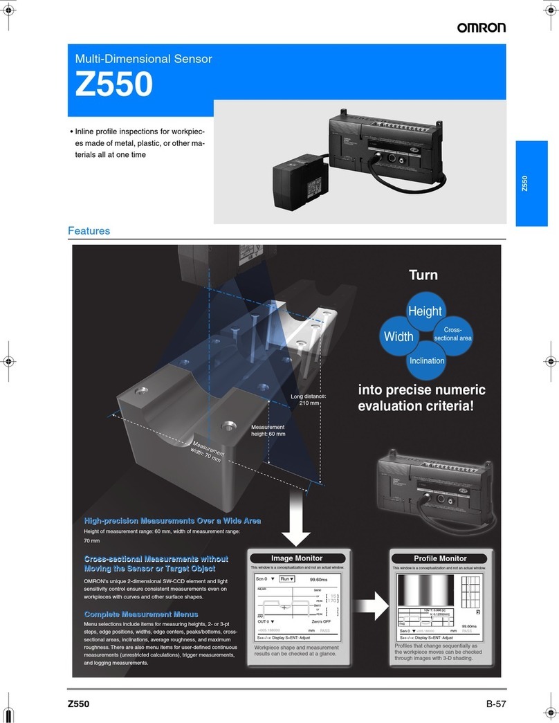
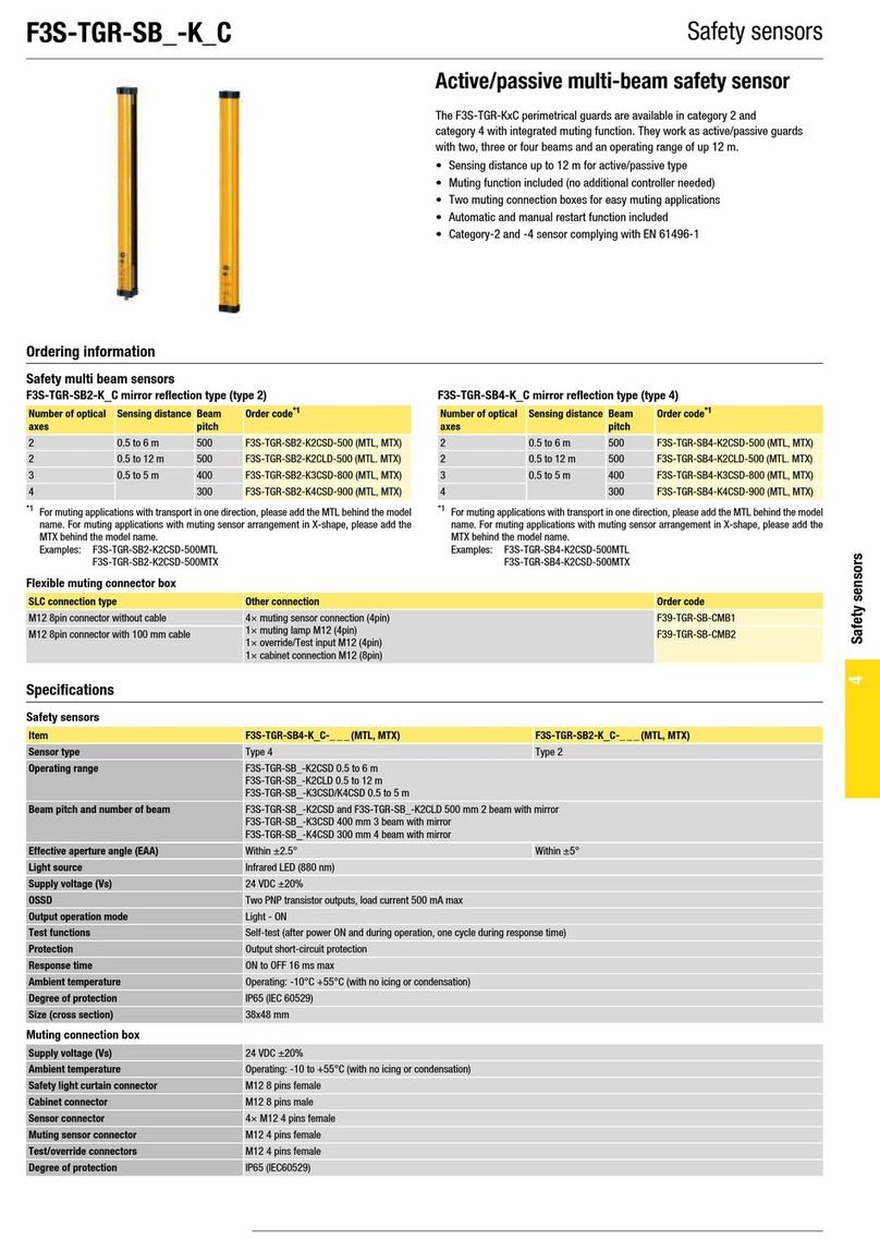
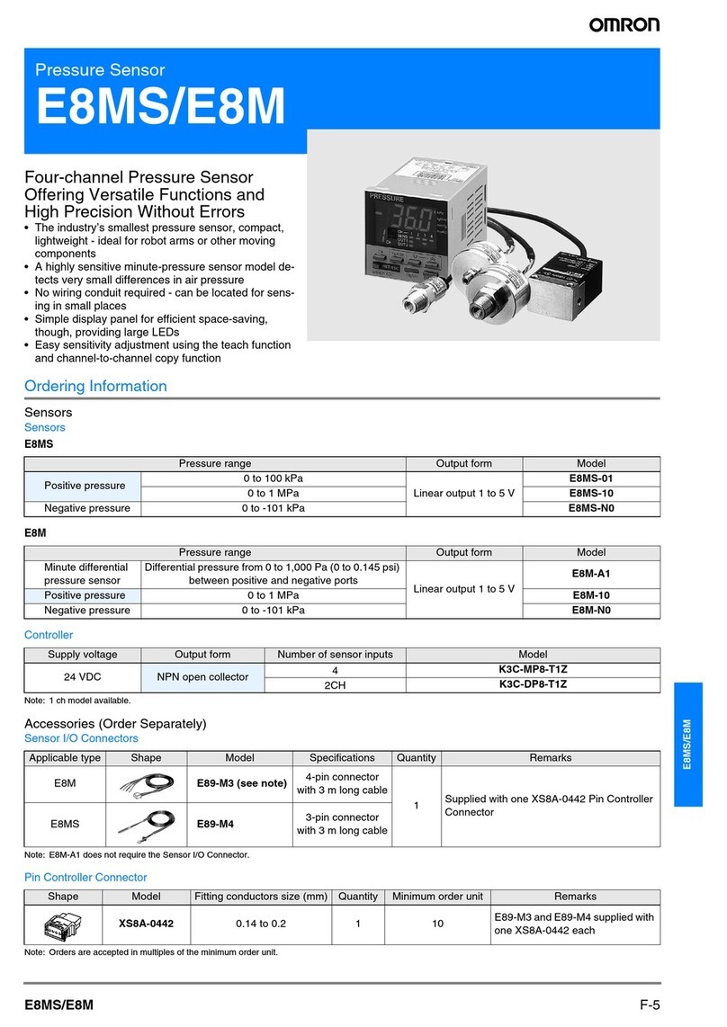
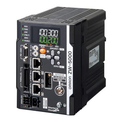
Omron Z550 User manual

Multi-Dimensional Sensor
Z550
Operation Manual
This manual explains menu operation method
and communication method with external
devices.
POWER
Cat.No. Z190-E1-02
Cat.No.Z190-E1-02 Multi-Dimensional Sensor Operation Manual
Authorized Distributor:
Cat. No. Z190-E1-02
In the interest of product improvement, specifications are
subject to change without notice.
Printed in Japan
0505-0.1M (1103) (M)
OMRON Corporation
Industrial Automation Company
Sensing Devices Division H.Q.
Application Sensors Division
Shiokoji Horikawa, Shimogyo-ku,
Kyoto, 600-8530 Japan
Tel: (81)75-344-7068/Fax: (81)75-344-7107
Regional Headquarters
OMRON EUROPE B.V.
Sensor Business Unit,
Carl-Benz-Str. 4, D-71154 Nufringen,
Germany
Tel: (49)7032-811-0/Fax: (49)7032-811-199
OMRON ELECTRONICS LLC
1 East Commerce Drive, Schaumburg, IL 60173
U.S.A.
Tel: (1)847-843-7900/Fax: (1)847-843-8568
OMRON ASIA PACIFIC PTE. LTD.
83 Clemenceau Avenue,
#11-01, UE Square,
239920 Singapore
Tel: (65)6835-3011/Fax: (65)6835-2711
OMRON (CHINA) CO., LTD.
Room 2211, Bank of China Tower,
200 Yin Cheng Road (M),
Shanghai, 200120 China
Tel: (86)21-5037-2222/Fax: (86)21-5037-2200

Operation Procedure and Reference Manual
The following shows main contents of operation steps and manuals. Select the manual suitable for your
purpose and read it before starting operation
INTRODUCTION
This operation manual describes the menu operations of the Controller. The Controller supports various
methods of inspection by combining measurement methods and various settings.
Please read this manual and related manuals thoroughly before using the Controller in order to operate it
properly.
POWER
POWER
Installation Wiring
Starting the Controller and Setting Workpieces in Place
Adjusting Images
Setting Measurement Conditions and Starting Measurement Outputting Data to External Device
Operation Manual
Explains menu operation method and communication method with external
devices.
Multi-Dimensional Sensor
Setup Manual
Multi-Dimensional Sensor
Operation Manual
Trademarks
•
Windows 95/98, Windows NT/2000 are registered trademarks of the Microsoft
Corporation in the United States and other countries.
• Hyper Terminal has been developed by Hilgraeve Inc. in the United States and are
also registered trademark of the Microsoft Corporation in the United States and other
countries.
This manual provides information on
system hardware. Be sure to read this
manualfirst.
This manual explains menu operation method
and communication method with external
devices.
Setup Manual
Contains information on safe use of the unit, series of procedures starting from
package content check, installation to cable connection, together with functions
and specifications of the unit and its peripheral devices.

INTRODUCTI SECTION 1SECTION 2SECTION 3SECTION 4
INTRODUCTION
SECTION 1 SECTION 2 SECTION 3 SECTION 4 SECTION 5 SECTION 6 SECTION 7
INTRODUCTION
SECTION 1
SECTION 2
SECTION 3
SECTION 4
SECTION 5
SECTION 6
SECTION 7
Table of Contents/Menus
Features
Basic Operations
Setting Measurement Conditions (Expert Menu)
Other Functions
System Settings
Communication with External Devices
Troubleshooting and Maintenance
Operation Manual
Multi-Dimensional Sensor Z550
Z550-MC10/-MC15
operation.bookPage1Monday,June6,200510:19AM

2
INTRODUCTION
Table of Contents
Z550
Operation Manual
INTRODUCTION
Table of Contents
Introduction
Table of Contents 2
Searching from Menu Hierarchy 5
Editor's Note 8
SECTION 1 Features 11
Features of the Controller 12
Operational Flow 14
SECTION 2 Basic Operations 17
Starting Controller and Displaying Profile 18
Menu Operations 20
Screen Types and Display Methods 25
Image Monitor 26
Profile Monitor 28
Digital Monitor 30
Trend Monitor 31
Learning Basic Operations (Conversational Menu) 32
Step 1 Selecting the Sensor Installation Method 32
Step 2 Selecting the Measurement Method 34
Step 3 Setting the Measurement Region 36
Step 4 Adjusting the Sensitivity 37
Step 5 Setting Workpiece Position Detection Method 38
Step 6 Setting Measurement Items 40
Step 7 Starting Measurements 43
Saving Settings and Exiting Controller Operation 45
operation.bookPage2Monday,June6,200510:19AM

3
Z550
Operation Manual
INTRODUCTION
Table of Contents
INTRODUCTION
SECTION 3 Setting Measurement Conditions(Expert Menu) 47
Adjusting Images
Detection Method
Measurement Setting
Auxiliary Setting
Measurement Mode
Selecting the Measurement Method 48
Setting the Measurement Region 50
Changing the Sensitivity Adjustment Method 51
Setting the Workpiece Position Detection Method 56
Setting Measurement Items 70
Setting Calibration 100
Setting Span and Offset 107
Setting the Judgment Conditions 109
Selecting Hold Conditions for Measurement Values 111
Selecting Inclination Compensation Error Handing 113
Select the Display Unit 115
Setting Averaging Number 117
Setting Trigger for Hold Measurement 118
Using the Logging Function 126
Setting the Detailed Conditions 128
Selecting Measurement Mode 134
SECTION 4 Other Functions 135
Using the Force-Zero Function 136
Changing the Screen Display 141
Switching Scenes 156
Testing Measurement Performance (Test) 159
Checking the Line Beam Position
(Surrounding Image) 164
Backing up Setting Data 166
operation.bookPage3Monday,June6,200510:19AM

4
INTRODUCTION
Table of Contents
Z550
Operation Manual
INTRODUCTION
SECTION 5 System Settings 173
Entering the System Mode 174
Switching Menus 175
Selecting the Sensor Installation Method 176
Selecting Input Source of Scene Switching 177
Setting Conditions at Startup 178
Selecting How Height Coordinates are Handled 179
Selecting the Displayed Number of Digits(Decimal Part) 180
Using the Download Function 181
Initialization 183
Checking System Version 184
SECTION 6 Communication with External Devices 185
Analog Output 186
Terminal Block 188
RS-232C 193
Timing Charts 222
SECTION 7 Troubleshooting and Maintenance 235
Troubleshooting 236
operation.bookPage4Monday,June6,200510:19AM

5
Z550
Operation Manual
INTRODUCTION
Searching from Menu Hierarchy
INTRODUCTION
Searching from Menu Hierarchy
Conversational Menu
Start settings p.32
Measurement method
p.34
Region
p.36
Sensitivity p.37
Detect setting p.38
Measurement setting
p.40
(OUT0 to 7)
Height p.72 Changing p.98
Upper p.109
Step: 2 pts p.40
Step: 3 pts p.75
Edge position p.78
Width p.81
Peak/bottom p.85
Angle p.87
Area p.89
Arithmetic average
roughness
Maximum roughness
p.92
Define p.95
Calibrate
Output
Delete p.99 Lower p.109
Hold p.111
Zero p.136
Span p.107
Offset p.107
Slant error
Unit p.115
Edge center p.84
p.92
p.113
operation.bookPage5Monday,June6,200510:19AM

6
INTRODUCTION
Searching from Menu Hierarchy
Z550
Operation Manual
INTRODUCTION
Expert Menu
Image
Measurement setting
p.70
(OUT0 to 7)
Height p.72 Changing settings p.98
Upper
p.109
Step: 2 pts p.74
Step: 3 pts p.75
Edge position p.78
Width p.81
Edge center p.84
Peak/bottom p.85
Angel p.87
Area p.89
Arithmetic average
roughness
Maximum roughness
p.92
Define p.95
Calibration
Output condition
Clearing settings p.99 Lower p.109
Hold p.111
Zero p.136
Span p.107
Offset p.107
Slant error
Unit p.115
Measurement method p.48
Region
Sensitivity p.51
Details p.54
Height/Reflectance p.57
Slant correct p.67
Detect setting p.56
Height/position
correct
Reflectance correct
Measurement Mode p.134
Output setting Analog p.186
Te r mi n a l s
p.188
RS-232C p.193
Extra setting # to avg p.117
Hold&Logging
Details p.128
p.50
p.60
p.64
p.92
p.113
p.118
p.126
operation.bookPage6Monday,June6,200510:19AM

7
Z550
Operation Manual
INTRODUCTION
Searching from Menu Hierarchy
INTRODUCTION
Parts Common between Two Menus
Adjustment menu (called from the measurement screen by pressing the SHIFT
and ENT Keys.)
Scene p.156
Setting
Run p.43
Tools
System p.174
Save p.45
Submenus below this item vary depending on the submenu.
Communication
specification
Setting menu p.175
Initialize p.183
Version p.184
Sensor installation p.176
Startup monitor p.178
Test measurement p.159
Surrounding image p.164
Backup p.166
Profile p.197
1st scene p.178
Dec. pts p.180
Scene selection p.177
Height coordinates p.179
Environment setting
p.196
Download p.181
Download p.181
Output setting Analog p.186
Terminals p.188
RS-232C p.193
Extra setting # to avg p.117
Hold&Logging
Details p.128
Display setting p.141
Test p.159
Sensitivity p.51
Measurement setting
p.70
p.118
p.126
operation.bookPage7Monday,June6,200510:19AM

8
INTRODUCTION
Editor's Note
Z550
Operation Manual
INTRODUCTION
Editor's Note
Page Format
step7䊁䉴䊃䈜䉎/⸘䉕㐿ᆎ䈜䉎
⸳ቯ䈚䈢᧦ઙ䈪ᱜ䈚䈒⸘䈪䈐䉎䈎䉕䊁䉴䊃䈜䉎䇸⏕䊝䊷䊄䇹䈫䇮ታ㓙䈮⸘䉕㐿ᆎ䈜
䉎䇸⸘䊝䊷䊄䇹䈮䈧䈇䈩⺑䈚䉁䈜䇯
⸳ቯ䈚䈢᧦ઙ䈪ᱜ䈚䈒⸘䈪䈐䉎䈎䉕䊁䉴䊃䈚䉁䈚䉊䈉䇯
╙2┨䇭ၮᧄᠲ
⸳ቯ䊝䊷䊄䉕ᛮ䈔䈩䇮⥄േ⊛䈮⏕䊝䊷䊄䈮䉍䉁䈜
⸘‛䈏⊕↹⚛䈮䈭䉎䉋䈉䈮㒢୯䇮㒢୯
䉕⸳ቯ䈚䈩䈒䈣䈘䈇
ᄖធ㐳ᣇᒻ䈫䈲
63
㪪㫐㫊㫋㪼㫄㩷㪪㪼㫋㫋㫀㫅㪾㫊
Setting Measurement Items
Up to eight measurement items can be set for each scene.
The measurement items that have been set for the outputs can be changed.
Changing Measurement Items
Clear any previously set measurement items in order to assign other measurement
items.
p.117
SECTION 3
Setting Measurement Conditions (Expert Menu)
Move the cursor to the output whose item is
to be changed, and press the ENT key.
1.
Select [Change].2.
The options will be displayed.
The setting screen for measurement range
appears.
The remaining procedures are the same as
those for measurement item setting.
Operation Manual 31
Step 1
Sensor Installation Condition
Step 3
Measurement region setting
Step 4
Sensitivity adjustment
Step 5
Detection method
Step 6
Measurement setting
Step 2
Measurement method selection
SECTION 3
䃂Title of each section
䃂Header
Indicates the contents of the pag
e
䃂Sub-header
䃂Overview
Describes the overview and
operation flow of the section.
䃂Screen display
Indicates the status of the screen displayed on the left side.
䃂Index label
Indicates to which section the
current page belongs and
the contents of the page.
This allows the user to find
the target page quickly.
䃂Operation procedure and supplementary explanation
Helpful information regarding operation and reference pages is
introduced here using symbols.
䃂Overview and points of
the function described
⸳ቯ
* This page does not exist.
Operation Manual
Scn 0䂯䇭Set䂯
OUT0:Height
OUT1:Step: 2 pts
OUT2:
OUT3:
OUT4:
OUT5:
OUT6:
OUT7:
Scn 0䂯䇭Set䂯
Change
Calibrate
Output
Delete
SECTION 5
operation.bookPage8Monday,June6,200510:19AM
9
Z550
Operation Manual
INTRODUCTION
Editor's Note
INTRODUCTION
Notational Conventions
Menu
In this manual, menu items displayed on the screen are enclosed with [ ]. Submenus are
separated using "/."
Example: Move to [Tools/Backup].
This statement indicates to select the [Tools] menu followed by [Backup] to move to the
Backup screen.
Key Operation on the Console
Example: Press the SHIFT and ESC Keys.
This statement indicates to press the ESC Key while pressing the SHIFT Key down on the
console.
Example: Select [Setting].
This statement indicates to move the cursor to [Setting] and press the ENT Key.
Visual Aids
Indicates information required to take full advantage of the functions and performance of the
product.Incorrect application methods may result in data corruption or damage to the product. Read
and follow all precautionary information.
Indicates points that are important to achieve the full product performance, such as operational
precautions and application procedures.
Indicates where to find related information.
Indicates information helpful in operation.
operation.bookPage9Monday,June6,200510:19AM

10
INTRODUCTION
Editor's Note
Z550
Operation Manual
INTRODUCTION
MEMO
operation.bookPage10Monday,June6,200510:19AM

SECTION 1 Features
11
Z550
Operation Manual
SECTION 1
Features
SECTION 1 explains the features of the Controller.
Features of the Controller 12
Operational Flow 14
operation.bookPage11Monday,June6,200510:19AM

12
SECTION 1 Features of the Controller
Z550
Operation Manual
SECTION 1
Features
Features of the Controller
The Controller is a device used to measure the height, width, and area of a workpiece.
It makes these measurements by irradiating laser beams onto the workpiece and receiving the reflected
light with the CCD inside the sensor.
Example: Inspection of LCD seal material application
RS-232C output
Measurement
value output
Judgment
output
Width
Cross-sectional area
Height
Profile output
Measurement
value output
Measurement items
Analog output
Terminal block
output
operation.bookPage12Monday,June6,200510:19AM

13
Z550
Operation Manual
SECTION 1 Features of the Controller
SECTION 1
Features
Simple Setup Using Menus
The Controller is equipped with two types of menus.
How to switch between the menus p.175
Monitoring While Viewing the Measurement Status
It is possible to visually keep track of how a workpiece is being detected on the monitor screen.
It is also possible to output the displayed profile (distribution of height measurement values) to a
PC.
Twelve Types of Measurement Items
The Controller allows selection from 12 different measurement items, such as height, width, and
cross-sectional area, according to the specific purpose.
Simultaneous measurement of up to 8 items can be performed.
p.70
If this is the first time you
operate the Controller
If you want to set up the
measurement conditions
as you wish by utilizing
various functions
Please use the conversational menu.
You can set up the measurement conditions with ease
by simply entering the information according to the
operation guidance that appears on the screen.
p.32
Please use the expert menu.
It is possible to switch to the expert menus after setting
up the conditions by using the conversational menu in
order to make further adjustments.
p.47
Scn 0䂯Run 䂯99.60ms
FAR
NEAR Sen0
LV
PEAK
LV
PEAK
Sen1
[ 15]
[ 170]
[ ]
[ ]
Sensor
Line beam
Profile
operation.bookPage13Monday,June6,200510:19AM

14
SECTION 1 Operational Flow
Z550
Operation Manual
SECTION 1
Features
Operational Flow
Preparation
for inspection
Turn the power supply on.
An error message is displayed
on the screen.
Select the measurement items
according to the purpose.
Back up the data.
Save the inspection conditions.
Set conditions for each model.
Set the conditions for
the system environment.
Set communication specification
and input/output format
with external devices.
Height Step: 2 pts
Step: 3 pts Edge position
Width Edge center
Peak/bottom
Angle
Area
Arithmetic average roughness
Maximum roughness
Define
Troubleshooting
Use the force-zero function.
Start up the Controller.
Start up the Controller
Controller
and display the profile.
Select the installation status
of the sensor.
of the sensor.
Select the measurement range.
Set the detection method of the
workpiece position as necessary.
Adjust the sensitivity.
Check the line beam
position
Set the measurement region.
Set the measurement region. Clear measurement items.
Change the screen display.
Change the settings of
measurement items.
Screen types and display methods
Set the measurement items.
Start measurements.
Start measurements. Initialize the .
Measurement
execution From setting conditions to execution
To learn about the basic flow from setting
the conditions to executing the measurement
p.18 p.25
p.32
p.32
p.34
p.36
p.37
(p.56 Expert Menus)
p.43
(p.48 Expert Menus)
(p.50 Expert Menus)
(p.51 Expert Menus) p.70
p.38
p.40
operation.bookPage14Monday,June6,200510:19AM

15
Z550
Operation Manual
SECTION 1 Operational Flow
SECTION 1
Features
An error message is displayed
on the screen.
on the screen.
Select the measurement items
according to the purpose.
Back up the data.
Back up the data.
Back up the data in a PC.
Save the inspection conditions.
Save the settings and shut
down the Controller.
Set conditions for each model.
Change scenes
(Scene function).
Set the conditions for
the system environment.
Environment settings
Set communication specification
and input/output format
with external devices.
Communication with external devices
Applied setting operations
Saving settings
Troubleshooting
Troubleshooting
Use the force-zero function.
Start up the Controller.
Controller
Select the installation status
of the sensor.
Select the measurement range.
Set the detection method of the
workpiece position as necessary.
Adjust the sensitivity.
Check the line beam
Check the line beam
position
position
Surrounding image
Set the measurement region.
Changing/deleting settings
Clear measurement items.
Change the screen display.
Change the settings of
measurement items.
measurement items.
Screen types and display methods
Set the measurement items.
Start measurements.
Initialize the
Initialize the
Controller.
.
To learn about the basic flow from setting
the conditions to executing the measurement
p.98
p.99
p.141
p.136
p.185
p.164
p.45
p.166 p.183
p.173
p.156
p.236
operation.bookPage15Monday,June6,200510:19AM

16
SECTION 1 Operational Flow
Z550
Operation Manual
SECTION 1
Features
MEMO
operation.bookPage16Monday,June6,200510:19AM

SECTION 2 Basic Operations
17
Z550
Operation Manual
SECTION 2
Basic Operations
SECTION 2 shows the basic menu operations of the Controller.
Starting Controller and Displaying Profile 18
Menu Operations 20
Input Device 20
Screen Structure 21
Menu Tree 22
Triangle Mark 23
Inputting Values 24
Screen Types and Display Methods 25
Image Monitor 26
Profile Monitor 28
Digital Monitor 30
Trend Monitor 31
Learning Basic Operations (Conversational Menu) 32
Step 1 Selecting the Sensor Installation Method 32
Step 2 Selecting the Measurement Method 34
Step 3 Setting the Measurement Region 36
Step 4 Adjusting the Sensitivity 37
Step 5 Setting Workpiece Position Detection Method 38
Step 6 Setting Measurement Items 40
Step 7 Starting Measurements 43
Saving Settings and Exiting Controller Operation 45
operation.bookPage17Monday,June6,200510:19AM

18
SECTION 2 Starting Controller and Displaying Profile
Z550
Operation Manual
SECTION 2
Basic Operations
Starting Controller and Displaying Profile
When the Controller is started up, the monitor displays the detection status.This is referred to as profile
(plotted height information).
No profile is displayed if the workpiece is not placed within the measurement range of the sensor.
Place the workpiece and adjust the sensor position while monitoring the displayed image.
1. Check that the basic components have been connected correctly.
Before connecting components or wiring power supply lines and grounding wires, be sure to refer to
the relevant section in Setup Manual.
Page 15 in Setup Manual
2. Turn the power supply to the monitor on.
3. Turn the power supply to the Controller on.
Console
㬍㬍 㬍 㬍 㬍 㬍 㬍 㬍 㬍 㬍 㬍 㬍
㬍 㬍 㬍
㬍㬍 㬍 㬍 㬍 㬍 㬍㬍
㬍 㬍 㬍 㬍 㬍 㬍 㬍 㬍 㬍 㬍
㬍 㬍
㬍 㬍 㬍 㬍 㬍 㬍 㬍
ESC TRIG
SHIFT
ENT
CONSOLE
Monitor
Sensor
Power Supply
operation.bookPage18Monday,June6,200510:19AM
Other manuals for Z550
2
Table of contents
Other Omron Accessories manuals

Omron
Omron E2C-CR5B User manual

Omron
Omron ZX-T - User manual

Omron
Omron E2C-EDA Series User manual

Omron
Omron ZS-HL - User manual

Omron
Omron F3SH-A - User manual

Omron
Omron F150-2 User guide

Omron
Omron E3C-LDA-N Series User manual

Omron
Omron ZX2-LDA User manual

Omron
Omron F160-2 - 2 User manual

Omron
Omron F210 User manual

Omron
Omron ZFV-SC150 Series User manual

Omron
Omron E2K-C User manual

Omron
Omron E2E - 2 User manual

Omron
Omron ZW-7000 Series User manual

Omron
Omron ZN-KMX21 Series User manual

Omron
Omron F3E User manual

Omron
Omron MS4800E User manual

Omron
Omron ZFX-C Installation manual

Omron
Omron ZFV-SC90 Series User manual

Omron
Omron FQ-CR10 Series User manual