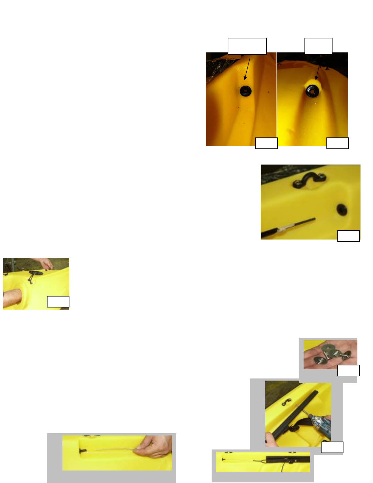
manuals.online logo
Brands
  1. Home
  2. •
  3. Brands
  4. •
  5. Ocean Kayak
  6. •
  7. Boat
  8. •
  9. Ocean Kayak Prowler Big Game User manual

Ocean Kayak Prowler Big Game User manual

1
1.2
1.4
1.3
INSTALLING THE PROWLER BIG GAME™ RUDDER
Parts Included:
Steering Parts: Foot Rail Parts: Rudder Parts: Retraction Parts:
4 Rubber 2 Rail Assemblies 4 10-32x ½” screws 1 Rudder Retraction
Grommets (includes steering Rudder Bracket Line (Deploy Line)
2 Lengths of cable) Rudder Blade 1 Bungee
Tubing 4 10-32x½” screws Rudder Body Kit: 1 Clam Cleat
2 Oval Copper 4 washers 1 Assembly of 4 10-32x1/2” screws
Crimps Screw/Nut/Washer/ 4 10-32 Nylok nuts
2 1” pieces black Bushing (large) 2 Strapeye
shrink tube 1 Assembly of 2 Blind Rivets
Screw/Nut/Washer/
Misc Roller Guide (small)
1 paper template Rudder Body
8 Riviets
1 Round, Black Plastic Disk
Tools Needed:
Drill 4” Hole saw Hot Glue Gun 3/8” Wrench
13/64” Drill Bit Lighter Soapy Water (as lubricant) Knife or Scissors
3/8” Drill Bit Crimper or Pliers #2 Phillips Head Screwdriver Tape
Rivet Gun Wire Cutter 7/16” Wrench Safety Goggles
Long Strip of Wire, 3 to 4 feet (ex: straightened coat hanger)
Please read the instructions thoroughly before installing the Prowler Big Game™ Rudder.
If you have questions, do not hesitate to contact Ocean Kayak (800-8-KAYAKS or
[email protected]) or your nearest Ocean Kayak dealer for more information.
1_Cutting Rear Access Hole:
1. Center the paper template on the
circular flat surface at the rear of the tank well.
Tape in place. Mark all nine holes with a pen.
Remove template. See 1.1.
2. Using 13/64” drill bit, drill all holes. See 1.2
3. Using 4” hole saw, cut a hole using the drilled center
hole as a guide. See 1.3 & 1.4.
1.1
2
2_Rudder Tubing:
1. There will be a total of 4 tubing holes through
which the steering lines will run. You will find
2 vertical notches at the rear of the foot well
ledge and 2 vertical notches at the stern of
the kayak. Using a 3/8” drill bit, drill straight
into the vertical surface of these notches.
Drill into the center of these notches, being
careful not to drill too high where the notches
narrow. See 2.1 & 2.2
2. Insert the 4 rubber grommets into each of the
drilled holes. Using scissors, cut the ends of the tubing at an angle to make inserting the
tubing easier.
3. Straighten a coat hanger (or use another length of straight
wire), and insert it through the tubing to keep it straight as you
are inserting it.
4. Spray the tubing with soapy water (or another lubricant) and
insert it into one of the footwell grommets. Continue pushing
the tubing through the grommet, keeping it in the space
between the tankwell and the outside wall of the kayak.
(Tilting the boat to the side that you are working on may help
keep the tubing in place.) See 2.3
5. Spray tubing with lubricant as needed.
6. Reach inside the stern access hole to pull the tubing through the hull and
guide it through the stern grommet. . Hold your fingers over the grommet
as you pull the tubing through so the grommet stays in place. Remove the
wire. See 2.4
7. Pull tubing taut. Rub the tubing immediately in front of the grommets with a
dry cloth to remove the lubricant and finish, creating a dull, sticky area.
Position the tubing so the dull part is at the grommets. This will prevent the
tubing from sliding through the grommets.
8. Pull tubing taut. Cut tubing 1” from grommets on both ends.
9. Repeat for other side.
3_Install Foot Rail Assemblies:
1. Place one rail assembly on the ledge above the foot well making sure the
pedal is toward the bow of the boat.
2. Note how the two pre-drilled holes in the track line up with
the brass screw inserts on the boat.
3. Using two ½” screws and washer sets, attach track to boat
using the inserts. Do not over-tighten! See 3.1 & 3.2
4. Repeat for other track.
Footwell Stern
2.22.1
2.3
2.4
3.2
3.1
3
4_Install Steering Lines:
1. Unwind and straighten steering cable.
2. Feed cable through tubing so all excess is out the stern grommet. See photo L.
3. Adjust the pedal on the track using the tri-glide, so that the cable loop is at the back edge
of the track when it is pulled straight. See 4.1 & 4.2
5_Install Rudder Body:
1. Attach the rudder bracket to the
transom using 4 machine screws (½”
long). See 5.1
2. Remove nut, washer, and 4” screw from
front of rudder body. Insert rudder body
between bracket mounting tabs. Put 4”
screw, washer, and nut back in place.
Using 7/16” wrench and screwdriver tighten self-locking nut until
screw is flush with bottom of nut. Do not over-tighten. The
rudder body should be able to swivel freely. See 5.2.
6_Install Rudder Blade:
1. Disassemble the larger screw/nut/washer/bushing.
2. Insert the bushing through the center hole of the rudder cam.
3. Insert the rudder blade into the rudder body, lining up the center
holes of the body and the cam.
4. Insert the screw through the bushing, and tighten washer and self-
locking nut with 7/16” wrench and screwdriver. Do not over-tighten.
Stop when the screw is flush with the nut. See 6.1.
7_Install Strap Eye and Clam Cleat:
1. See 7.1 & 7.2 for strap eye and clam cleat placement on
right side of boat where seat well and tank well meet
(where deck line was just removed). There will be four
“O” marking the spots where the rivets and screws will be
placed.
2. Using 13/64” drill bit, drill the two “O” where the strap eye
and cleat will go. Drill out the 2 “O” for the rope guide.
3. Attach the cleat and strap eye using a 10-32x1/2 screw, o-
ring, and nut. Align the cleat and strap eye in a straight line
and drill out the other holes. Attach as before.
4. Mount the rope guide strap eye using blind rivets.
6.1
Center Hole
Clam cleat strap eye
Rope guide
tri-glide
“O” marks
4.2
4.1
5.1 5.2
“O” marks
7.1
7.2
4
8_Install Rudder deploy/retract Line:
1. Feed the retraction line under the roller guide on the rudder body.
See 8.1
2. Keep the retraction line to the right side of the rudder blade. Bring it
under and then up and around the gray cam (on the rudder blade)
pulling enough rope to touch the clam cleat.
3. Thread the retraction line through the holes on the top of the rudder
blade. Starting on the right hand side, insert the retraction line from
right to left through the middle hole. Then insert
the line from left to right through the front hole.
Then insert the line a final time from right to left
through the rear hole. See 8.2
4. Thread the retraction line back under the roller
guide. See 8.3
5. Thread both lines through the rope guide strap
eye
9_Knotting deploy/retraction line and bungee together:
1. There will be two knots that will hold the bungee and retraction line together: one on the
retraction line (Top) and on the deploy (bottom). Each knot is made up of two knots
which are positioned side by
side. Photo 9.1 shows what
the finished attachment will
look like.
2. With rudder blade in up position, begin first knot by taking the retract line and looping
over the bungee line two times, from left to right in a crisscross pattern. See 9.2.
Then take the rope and pass it through the
loops, from left to right and tighten. The knot
should be 1” from the clamcleat.
3. Working to the left of the previous
knot, begin the second half of knot #1
by taking the bungee and looping it
over the retract line two times, from
right
to left
in a
crisscross pattern. See 9.3. Then take the bungee and
pass it through the loops, from right to left and tighten.
8.2
8.1
8.3
9.1
Retract
Deploy
9.2
9.3
5
10.3 10.4
4. Slide this knot over so it is snug up to the previous knot. Pull long ends of retraction line
and bungee to tighten. See 9.4.
5. Take the other end of the bungee and pass it through the
strap eye, from the top.
6. Move the rudder blade to the down position.
7. Take the deploy line and tie the same knot as before
about an inch from the clam cleat around the bungee.
See 9.5
8. Pull the
other end
of the
bungee to apply tension. Keeping the
tension, tie the free end of the bungee
around the deploy line as before. See 9.6
Pull the knots together. Refer to 9.4 Cut off
the excess rope
and bungee leaving
about an inch. Use
a lighter or other
heat source to melt
the ends of the
rope. Use hot glue to seal the ends of the bungee.
NOTE: When the rudder blade is in the up position, the top knot should be about one inch
behind the clam cleat. When the rudder blade is in the down position, the bottom knot
should be about one inch behind the clam cleat.
10_Attach Steering Lines:
1. Unscrew the nut and remove it plus the 2 washers from left
wing of the rudder body.
2. Take one of the pieces of black shrink tube and insert it
onto the cable that is on the left side. Followed by a copper
crimp. See 10.1
3. Take the end of the cable and re-insert it through the copper
crimp creating a loop. See 10.1
4. Place this loop around the screw on the wing.
5. Tighten loop using copper crimp until crimp is just in front of the
wing. See 10.2. Make sure rudder body is still properly aligned
and that the cable is pulled straight.
6. Hold crimp in place and remove the loop from
the screw.
7. Using the crimpers (or pliers), crimp in 3 places,
both ends and the middle, to secure the cable.
See 10.3 & 10.4
10.1
10.2
9.4
9.5
9.6
6
10.5
10.610.6
8. Cut the loose cable end, close to the copper crimp.
9. Slide the black shrink tube over the copper crimp and
the cut end of the cable. Using the lighter, heat the
shrink tube until it shrinks and molds over the crimp
and the cut end of the cable. Do not overheat! See
10.5
10.Put one washer back onto screw. Place cable loop
on the screw. Add the other washer and self-locking
nut, and tighten using 3/8” wrench and screwdriver.
Do not over-tighten. Stop when the screw is flush
with the nut. See 10.6.
11.Tighten the pedal strap, using the tri-glide, to take up
any loose cable, keeping the cable loop at the end of
the track.
12.Attach the other side the same way.
11_Sealing Rear Access Hole:
1. Do this step last! Before starting, make sure there is nothing left in the hole. A vacuum
can be used to suck up any small debris.
2. Silicone around the edge of the hole. See 11.1.
3. Insert four rivets into the four smaller holes of the black plastic disk.
4. Position disk over access hole, lining up holes and rivets. Then
insert additional four rivets. See photo 11.2.
5. Rivet into place, using wire cutter to remove tops of rivets. See 11.3
& 11.4
Washer
Cable
Washer
Nut
11.1
11.2 11.3
11.4
A

Other Ocean Kayak Boat manuals

Ocean Kayak Classic Big Game User manual

Ocean Kayak

Ocean Kayak Classic Big Game User manual

Ocean Kayak VENUS 11 User manual

Ocean Kayak

Ocean Kayak VENUS 11 User manual

Ocean Kayak SCUPPER PRO 14561 User manual

Ocean Kayak

Ocean Kayak SCUPPER PRO 14561 User manual

Ocean Kayak Nalu User manual

Ocean Kayak

Ocean Kayak Nalu User manual

Ocean Kayak Trident 11 User manual

Ocean Kayak

Ocean Kayak Trident 11 User manual

Ocean Kayak TORQUE Configuration guide

Ocean Kayak

Ocean Kayak TORQUE Configuration guide

Ocean Kayak TORQUE Configuration guide

Ocean Kayak

Ocean Kayak TORQUE Configuration guide

Ocean Kayak The Torque Configuration guide

Ocean Kayak

Ocean Kayak The Torque Configuration guide

Ocean Kayak Kayak User manual

Ocean Kayak

Ocean Kayak Kayak User manual

Ocean Kayak Scrambler 11 User manual

Ocean Kayak

Ocean Kayak Scrambler 11 User manual

Popular Boat manuals by other brands

Williams sportjet Owner's handbook

Williams

Williams sportjet Owner's handbook

Elan E4 owner's manual

Elan

Elan E4 owner's manual

Sport Boats Dolphin 8.8' Air Floor Owner's operating manual & safety information

Sport Boats

Sport Boats Dolphin 8.8' Air Floor Owner's operating manual & safety information

Trophy 1703CC owner's manual

Trophy

Trophy 1703CC owner's manual

Yamaha WaveRunner SuperJet 2015 owner's manual

Yamaha

Yamaha WaveRunner SuperJet 2015 owner's manual

KAYAKS2FISH NEXTGEN10 MK2 owner's manual

KAYAKS2FISH

KAYAKS2FISH NEXTGEN10 MK2 owner's manual

Windward Passage Boats operating manual

Windward Passage

Windward Passage Boats operating manual

Dehler 31 Owner's handbook

Dehler

Dehler 31 Owner's handbook

Pro-Line Boats Pro Line 19 Sport 2004 owner's manual

Pro-Line Boats

Pro-Line Boats Pro Line 19 Sport 2004 owner's manual

Crivit IAN 71536 Instructions for use

Crivit

Crivit IAN 71536 Instructions for use

Yamaha AR195 Owner's/operator's manual

Yamaha

Yamaha AR195 Owner's/operator's manual

Key West Boats 2015 176BR Quick guide and schematics

Key West Boats

Key West Boats 2015 176BR Quick guide and schematics

BENETEAU Oceanis 41.1 2017 Owners’ Notes

BENETEAU

BENETEAU Oceanis 41.1 2017 Owners’ Notes

Performance Catamarans Prindle 18-2 owner's manual

Performance Catamarans

Performance Catamarans Prindle 18-2 owner's manual

Zodiac MEDLINE 9 manual

Zodiac

Zodiac MEDLINE 9 manual

Speed Sails Enterprise Tuning guide

Speed Sails

Speed Sails Enterprise Tuning guide

Cutwater C-24 Coupe owner's manual

Cutwater

Cutwater C-24 Coupe owner's manual

Grady-White Boats Canyon 336 owner's manual

Grady-White Boats

Grady-White Boats Canyon 336 owner's manual

manuals.online logo
manuals.online logoBrands
  • About & Mission
  • Contact us
  • Privacy Policy
  • Terms and Conditions

Copyright 2025 Manuals.Online. All Rights Reserved.