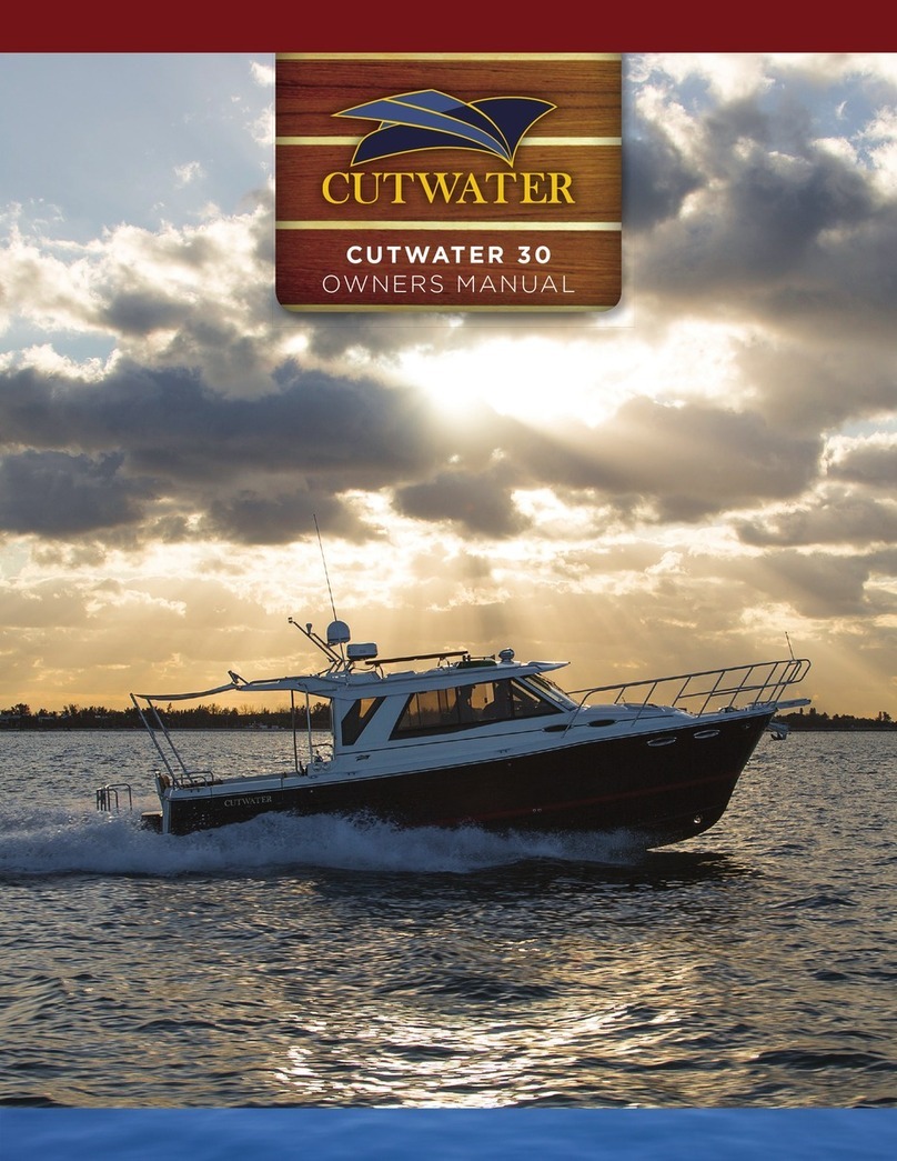
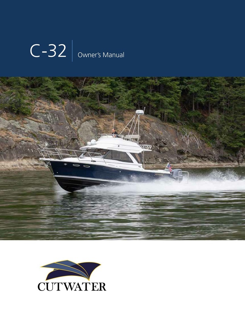
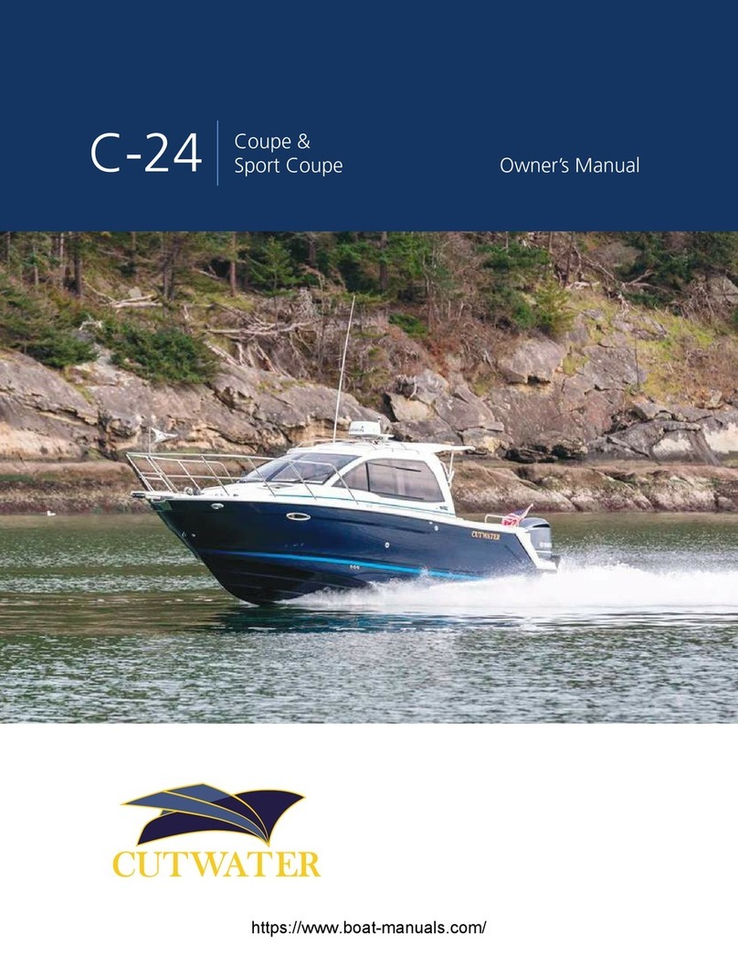
Cutwater C-24 Coupe User manual

C-24 Center Walkaround Owner’s Manual

TABLE OF CONTENTS
2
Table Of Contents ......................................................................................................................... 2
Congratulations ............................................................................................................................. 3
Safety .................................................................................................................................................. 3
Garbage Disposal & Oil Overboard Placards ................................................................... 4
Symbol Glossary ........................................................................................................................... 5
Specifications (Subject To Change Without Notice) .................................................. 6
Equipment Location .................................................................................................................... 7
Starboard Fittings ................................................................................................................. 7
Port Fittings ............................................................................................................................. 8
Stern Components ............................................................................................................... 9
Main Cabin And Cockpit Lights ...................................................................................... 10
Fuel System, Engine, Generator ..................................................................................... 11
Raw Water / Sea Strainer System ................................................................................ 12
Fresh Water Plumbing System ....................................................................................... 13
Bilge Pump System .............................................................................................................. 14
Waste System With Macerator Pump ......................................................................... 15
Battery Configuration ......................................................................................................... 16
Fuse Location & Values ...................................................................................................... 17
12V Helm Control Operation ............................................................................................ 18
Cutwater C-24 Wiring Schematic (Acc. 1) ................................................................ 19
Cutwater C-24 Wiring Schematic (Acc. 2) ............................................................... 20
Cutwater C-24 Wiring Schematic (Acc. 3) ............................................................... 21
Cutwater C-24 Wiring Schematic (P.D.P.) ................................................................. 22
Cutwater C-24 Working Deck ................................................................................................ 23
Care And Maintenance ............................................................................................................... 24
Example Of A Preparation For The Road Checklist ............................................ 24
Example Of A Spring Pre-Launch Checklist ............................................................ 25
Example Of Winter Storage Checklist ........................................................................ 26
Warning Label Locations .......................................................................................................... 27
Contacts ............................................................................................................................................. 28

3
CONGRATULATIONS
The Cutwater family has a passion for boating. We are committed to
continuous process improvement in all areas that aect our customer’s
satisfaction with our products and providing great customer service.
SAFETY
Safety is always a concern at Cutwater. Please read all manuals to ensure
that equipment is used in a safe manner. We highly recommend atten-
dance in a Coast Guard approved boating safety course. Such courses
are available from the Coast Guard directly or from boating organiza-
tions. Owners should have annual inspections to ensure that all safety
equipment is current.
Operating, servicing and maintaining
a recreational marine vessel can expose
you to chemicals including engine exhaust,
carbon monoxide, phthalates, and lead,
which are known to the State of California
to cause cancer and birth defects or other
reproductive harm. To minimize exposure,
avoid breathing exhaust, service your vessel
in a well-ventilated area and wear gloves or
wash your hands frequently when servicing
this vessel. For more information go to
www.P65warnings.ca.gov/marine.
Prop 65 Boat Owner’s
Manual Image
Notes on use of the above:
27 CCR § 25607.18
§ 25607.18. Recreational Vessel Exposure Warnings -
Method of Transmission. [Operative August 30, 2018]
(a) A warning for exposures that occur during the operation
or maintenance of a recreational vessel as defined in California
Harbor and Navigation Code Section 651(t) meets the
requirements of this subarticle if it complies with the content
requirements in Section 25607.19 and is provided as follows:
(1) The warning is printed in the owner's manual for the
specific recreational vessel, in no smaller than 12-point type
enclosed in a box printed or affixed to the inside or outside
of the front or back cover of the manual or on the first page
of the text, and;
(2) The warning is provided on a hang tag readily visible from
the helm of the vessel printed in no smaller than 12-point type.
MAXIMUM CAPACITIES
8PERSONS OR 1450 LBS.
2350 LBS, PERSONS, MOTOR AND GEAR
300 HORSEPOWER MOTOR MAX
THIS BOAT COMPLIES WITH U.S. COAST GUARD SAFETY
STANDARDS IN EFFECT ON THE DATE OF CERTIFICATION
MANUFACTURER: FLUID MOTION LLC
MODEL: CUTWATER 24
KENT, WA

HEADLINE
44
Required by the USCG in a language all passengers understand. These
are installed at the factory. If damaged or missing after use they should
be replaced. Text should cover approximately the following:
GARBAGE DISPOSAL
OIL OVERBOARD
GARBAGE DISPOSAL & OIL OVERBOARD PLACARDS
DISPOSAL OF ALL GARBAGE PROHIBITED
EXCEPT OTHERWISE SPECIFIED
THE ACT TO PREVENT POLLUTION FROM SHIPS (MARPOL ANNEX V) PLACES
LIMITATIONS ON THE DISCHARGE OF GARBAGE FROM VESSELS. IT IS ILLEGAL TO
DUMP PLASTIC TRASH ANYWHERE IN THE OCEAN OR NAVIGABLE WATERS OF THE
UNITED STATES. IT IS ALSO ILLEGAL TO DISCHARGE GARBAGE IN THE NAVIGABLE
WATERS OF THE UNITED STATES, INCLUDING THE GREAT LAKES. THE DISCHARGE
OF OTHER TYPES OF GARBAGE IS PERMITTED OUTSIDE OF SPECIFIC DISTANCES
OFFSHORE AS DETERMINED BY THE NATURE OF THAT GARBAGE.
VIOLATION MAY RESULT IN HEAVY PENALTIES
TYPE OF WASTE
PLASTICS - INCLUDES SYNTHETIC ROPES,
FISHING NETS, AND PLASTIC BAGS
FLOATING DUNNAGE, LINING AND
PACKING MATERIALS
FOOD WASTE, PAPER, RAGS, GLASS,
METAL, BOTTLES, CROCKERY, OR
SIMILAR REFUSE
COMMINUTED OR GROUND FOOD
WASTE, PAPER, RAGS, GLASS, ETC.
DISCHARGE PERMITTED
PROHIBITED IN ALL AREAS
PROHIBITED LESS THAN 25 MILES
FROM NEAREST LAND
PROHIBITED LESS THAN 12 MILES
FROM NEAREST LAND
PROHIBITED LESS THAN 3 MILES
FROM NEAREST LAND
DISCHARGE OF OIL PROHIBITED
THE FEDERAL WATER POLLUTION CONTROL ACT PROHIBITS THE DISCHARGE
OF OIL OR OILY WASTE INTO OR UPON THE NAVIGABLE WATERS OF THE
UNITED STATES, OR THE WATERS OF THE CONTIGUOUS ZONE, OR WHICH MAY
AFFECT NATURAL RESOURCES BELONGING TO, APPERTAINING TO, OR UNDER
THE EXCLUSIVE MANAGEMENT AUTHORITY OF THE UNITED STATES. IF SUCH
DISCHARGE CAUSES A FILM OR DISCOLORATION OF THE SURFACE OF THE WATER
OR CAUSES A SLUDGE OR EMULSION BENEATH THE SURFACE OF THE WATER,
VIOLATORS ARE SUBJECT TO SUBSTANTIAL CIVIL PENALTIES AND/OR CRIMINAL
SANCTIONS INCLUDING FINES AND IMPRISONMENT.

HEADLINE
5
SYMBOL GLOSSARY
5
STE
OPT
Attention! – Important Operating or Maintenance Instructions
Attention! – Electrical Shock Hazard
Fresh Water
Waste Tank
Fuel
Standard Equipment
Optional Equipment
Hints

HEADLINE
6
SPECIFICATIONS
6
(Subject to Change Without Notice)
C-24 Center Walkaround
Length rigged LOA (motor down) ................................................. 29’ 2” 8.9 m
Length rigged LOA (motor up) .......................................................31’ 9.5 m
Beam .............................................................................................................8’ 6” 2.6 m
Draft (motor down) ...............................................................................32” .8 m
Draft (motor up) ......................................................................................19” .5 m
Weight, dry ................................................................................................6,300 lbs 2,858 kg
Bridge clearance (no top) ..................................................................7’ 1” 2.2 m
Bridge clearance (w/ ht/bimini) ......................................................8’ 2” 2.5 m
Bridge clearance (w/ ht & radar) ....................................................9’ 0” 2.7 m
Height on factory trailer (no top) ...................................................9’ 4” 2.8 m
Height on factory trailer (w/ht/bimini) ........................................ 11’ 4” 3.5 m
Height on factory trailer (w/ht & radar) ......................................12’ 2” 3.7 m
Fuel capacity .............................................................................................116 U.S. Gal 439.1 L
Water capacity ......................................................................................... 26 U.S. Gal 98.4 L
Holding tank capacity ..........................................................................13 U.S. Gal 49.2 L

HEADLINE
7
EQUIPMENT LOCATION
7
STARBOARD FITTINGS
1 2 3 4 5 6 7 8 10 11 13 14 15 16 17 18 19 20 21 22
9 12
Keep all vents, drains and exhausts clear of any
obstructions to ensure proper performance of each
system.
STE
11
12
14
15
16
17
19
18
➎
➊
➓
➊Swim Step Drain
➋Fuel Fill
➌Aft Bilge
➍Forward Aft Bilge
➎Ski Pole
➏Waste Pumpout
➐Waste Tank Vent
➑Trailering Side Marker Light
➒Macerator Thru-Hull
➓VHF Antenna
Anchor Light
Radar
Water Fill
Water Tank Vent
Bow Thruster
Nav Light
Bow Eye
Windlass
Horn
Bow Pulpit with Beaching
Ladder & Anchor Roller
Anchor Locker Drain
Rocket Launchers
11
13
12
14
15
16
17
18
19
20
20
21
21
➑
➒
➐
➌➍
➋
➏13
22
22

HEADLINE
88
STE
PORT FITTINGS
1 2 3 4 5 6 8 9 10 11
7
Keep all vents, drains and exhausts clear of any obstructions to
ensure proper performance of each system.
➎
➌
➋
➊
➓
➊Bow Pulpit with Beaching
Ladder & Anchor Roller
➋Nav Light
➌Bow Eye
➍Bow Thruster
➎Head Sink Drain
➏Forward Bilge Drain
➐Radar
➑Anchor Light
➒Trailering Side Marker Light
➓VHF Antenna
Rocket Launchers
➍
➏
➑
➐
➒
11
11

➊Swim Platform Courtesy Lights
➋Fuel Fill
➌Cockpit Scupper Drains
➍ Underwater Lights
➎Drain Plug
➏Trailer Turn/Brake Lights
➐Rod Holders
➑Flagsta Mount
➒Towing Strapdown
➓Trim Tab Ram
Shower
Ski Pole
Swim Ladder
Zincs
Lower Unit Zinc
Motor Mount Zinc
9
STERN COMPONENTS
STE
1 2 3 4 5 6 7 8 9 10 11 12 13 15 16
14
➊➊
➋
➌➌
11
➑
➐➐
➓ ➓
11
12
13
➍
➏
➒
➏
➍
➒
➎
12
13
14
15
16
14
14
15
16

10
MAIN CABIN AND COCKPIT LIGHTS
Switch on
fixture
Blue LED ceiling, speaker &
navigation lights – switch on dash
Courtesy / LED lights
Underwater lights (opt.)

FUEL SYSTEM, ENGINE
11
STE
Yamaha 250
Yamaha 300, Kicker (9.9 Yamaha)
Fuel Tank
Kicker primer bulb
Main primer bulb
Fuel fill
Sender
Vent
Fuel filter / separator

12
RAW WATER / SEA STRAINER SYSTEM
STE
• Sea strainer for head and raw water wash down pump.
Raw Water Washdown
Pump (optional)
Marine Toilet
Head Raw Water
Thru-hull/Valve
Sea Strainer
Live Well
(optional)
Live Well
Valve (optional)

13
FRESH WATER PLUMBING SYSTEM
STE
26 Gallon Fresh Water Tank, 3.5 GPM Fresh Water Pump.
Disinfecting The Fresh Water System
Water fill
Water vent
Water Pump
with removable
strainer
Head
sink
Transom
shower
Transom
sink
H-23
7/14
© 2014 American Boat & Yacht Council, Inc.
6
APPENDIX - POTABLE WATER SYSTEMS
The information contained in this appendix provides supplementary data about disinfecting a potable water system.
A SUGGESTED METHOD OF DISINFECTION
Perform the following steps in the order indicated:
a. Flush entire system thoroughly by allowing potable water to flow through it;
b. Drain system completely;
c. Fill entire system with a chlorine solution having a strength of at least 100 parts per million, and allow to
stand for one (1) hour. Shorter periods will require greater concentrations of chlorine solution. See Table I
d. Drain chlorine solution from entire system;
e. Flush entire system thoroughly with potable water;
f. Fill system with potable water.
Table I shows how much disinfecting agent is required to make up various quantities of 100 parts per million chlorine
solution.
TABLE I – CHLORINE CONCENTRATIONS
Amount of chlorine compound required for 100 ppm solution
Solution
(Gallons)
Chlorinated Lime
25% (ounces)
High Test Calcium
Hypochlorite 70%
(ounces)
Liquid Sodium
Hypochlorite 1% (quarts)
5
0
.
3 0
.
1 0
.
2
10 0
.
6 0
.
2
0
.
4
1
5
0
.
9 0
.
3 0
.
6
2
0 1
.
2
0
.
4 0
.
8
30 1
.
8 0
.
6 1
.
2
5
0 3
.
0 1
.
0
2
.
0
100 6
.
0
2
.
0 4
.
0
NOTE: This table contains information taken from the Handbook on Sanitation of Vessel Water Points,
Public Health Service Publication No. 274 - Reprinted June 1963.
* * * * *
Origin and Development of ABYC H-23, Water Systems for Use on Boats
ABYC H-23, Installation of Potable Water Systems for Use on Boats was first published in 1970. Revised editions
were published in 1974, 1983, 1996, and 2008. In 2014 the title was revised to H-23, Water Systems for Use on
Boats. The 2014 version is the work of the Hull Piping Project Technical Committee.
* * * * *
ABYC technical board rules provide that all reports, including standards and technical information reports, are
advisory only. Their use is entirely voluntary. They represent, as of the date of publication, the consensus of
knowledgeable persons, currently active in the field of small craft, on performance objectives that contribute to small
boat safety.
The American Boat & Yacht Council assumes no responsibility whatsoever for the use of, or failure to use, standards
and technical information reports promulgated by it, their adaptation to any processes of a user, or any consequences
flowing therefrom.
Prospective users of the standards and technical information reports are responsible for protecting themselves
against liability for infringement of patents.
The American Boat and Yacht Council standards and technical information reports are guides to achieving a specific
level of design or performance, and are not intended to preclude attainment of desired results by other means.

14
BILGE PUMP SYSTEM
Forward bilge
pump (1100 GPH)
Aft bilge pump
(1100 GPH)
Thru-hulls
High Water Alarm
Thru-hull
Forward bilge pump
under access hatch (900 GPH)
High Water Switch
STE
The bilge pumps operate automatically by checking for water every 2.5 minutes
even with battery switches and breakers in the OFF position.
However, the bilge pumps will run continuously once their switches are placed in the
on position. Monitor the outflow accordingly. Do not run when dry.
• All manual bidge pump switches are located at the helm.
• V-berth switch is labeled “ACCY”.
12V 1100 GPH
12v 900 GPH

15
WASTE SYSTEM WITH MACERATOR PUMP
STE
13 Gallon Tank with standard pump out, and vent
Waste tank pump out stations are widely available.
Please follow the directions carefully for the pump out equipment you are using to
avoid damage to the waste system.
Boat owner is responsible for following all applicable laws when using the
macerator system to pump out into the surrounding waters.
Overboard shuto valve is accessed under the galley sink above the
pump area.
Macerator pump out
Holding Tank
Waste pumpout
Macerator out
Macerator
pump
Macerator
shut off
Toilet
Waste vent

STE
16
BATTERY CONFIGURATION
STE
2 House Batteries, 1 Engine Battery
1
12
3
3 bank battery charger
Ground/bonding bus
Solar controller (opt.)
30 Amp galvanic isolator (opt.)
Thruster battery switch
Thruster ANL fuse 200A
Solar controller panel (opt.)
STE
House, start, & battery parallel switches and breakers are located in the access
hatch beneath the stern sink.
1 Thruster Battery. Thruster battery, switch and ANL fuse are located in the forward
sink cabinet.
Once the EMERGENCY PARALLEL switch is placed in the on position the
power from the HOUSE batteries will be transferred to the ENGINE battery.
Use only for EMERGENCY starting of the engine.
If the house bank drops below 10.8v you must reset the charging relay by
switching on the parallel while the engine is running or while plugged into
shore power.
Battery Banks
1= House
2= Engine
3= Thruster
O
OFF
EMERG
PARALLEL
O
OFF
HOUSE
+ -
O
OFF
START
+ -
O
OFF
HOUSE
+ -
—
ON
HOUSE
+ -
ON
OFF
VOLTAGE SENSOR RELAY
O
OFF
EMERG
PARALLEL
O
OFF
HOUSE
+ -
O
OFF
START
+ -
O
OFF
HOUSE
+ -
—
ON
HOUSE
+ -
ON
OFF
VOLTAGE SENSOR RELAY
100 House 30 24/7

17
FUSE LOCATION & VALUESFUSE LOCATION & VALUES
STE
Dash fuse blocks are located behind a hinged access panel in the head.
Fuses are automotive blade type and all values shown below are in Amps.
SALTWATER PUMP
FUSE BLOCK #1
STEREO MEM
VHF
MAIN SCREEN
STBD PWR 1
STBD PWR 2
RFR POWER
FUSE BLOCK #2
12DC OUTLET
USB OUTLET
COCKPIT LIGHTS
PUCK LIGHT
DN RIG PORT (OPT)
A-BILGE FWD
FUSE BLOCK #3 - 24/7
A-BILGE MID
A-BILGE AFT
STEREO MEM
CO MONITOR
HIGH BILGE ALARM
DN RIG STBD (OPT)
FISHBOX
PORT PWR 1
PORT PWR 2

18
12V HELM CONTROL OPERATION
The bilge pumps operate automatically with electronic float switches regardless of
battery switch position. This should be tested weekly.
However, the aft, mid and forward pumps will run continuously once their switches
are placed in the on position. Monitor the outflow accordingly. Do not run when dry.
HORN NAV
ANC
CHRT
LTS
CTSY
LTS WIPER ACC 1
BLO-
WER
MID
BLG
AFT
BLG
FRESH
WTR
MAC
PUMP ACC 2
At Helm
At Helm
Resettable switch breakers
PORT
STARBOARD

C-24-CW/DC Accessories 1
ELECTRICAL SCHEMATIC
+12V
Helm Fuse Block #1
15A
30A RED 10
10A
Stereo
Stereo
Memory
To 24/7 Fuse
Block #3
15A
10A
RED 16
Stereo Deck - see MFR Schematic
RED 14 ORG 14 + -
YEL 16
-12V
GND
YEL 14
LF
15A
VHF RED 16
RF LR
VHF Radio - see MFR Schematic
Wash
Down
10A RED 10 GRN/BRN 16
WashDown
MYEL 16
RR
YEL 16
WHT/YEL16
Garmin Display - see MFR Schematic
RED/YEL 16 YEL 16
GRY/RED 16 Nav
Compass
Anchor
GRY/BLK 16
YEL 16
YEL 16
YEL 16
5A
CHART LT BLU/YEL 16 BLU/YEL 16 YEL 16
CRTSY LT BLU/WHT 16 BLU/WHT 16
YEL 16
5A
5A
Wiper Park
Wiper
5A RED 16
ORG/GRN 16
RED/GRN 16 MYEL 16
Horn
30A RED 10
Stbd Switch
Panel
ACC 1
Switch
RED 16
RED/YEL 14
10A
PUR/BRN 14 PUR/BRN 14
7.5A
RED/BRN 14 RED/BRN 14
7.5A
BRN/BLU 14 YEL 14
15A
Garmin
Nav/Inst
M
M
M
30A RED 10
Port Switch
Panel
BLOWER
30A RED 10
Port Switch
Panel
5A
MID BILGE
AFT BILGE
To Acc. 3 Schematic
To Acc. 3 Schematic
YEL 14
FRESH
WATER
RED/YEL 14
BRN/BLU 14 M
BRN 10 YEL 10
20A
MACE-
RATOR M
BRN 10
ACC 2
Switch
RED 16
5A
Stbd Switch
Panel
19
C-24 CW WIRING SCHEMATIC (ACC. 1)

C-24 CW WIRING SCHEMATIC (ACC. 2)
20
C-24-CW/DC Accessories 2
ELECTRICAL SCHEMATIC
+12V
Helm Fuse Block #2
-12V
GND
15A ORG/PUR 10 Refrigerator - see MFR Schematic YEL 10
Refrigerator
12V Outlet
HELM
15A RED 14 12V YEL 14
USB Outlet
HELM
5A RED/BLK 16 USB YEL 14
10A BLU/RED16
Cockpit Sw
Panel
GRY/BLU 16
BLU/BLK16 BLU/BLK16
YEL 16
5A
5A
Cockpit
Lights
GRY/BLU 16
YEL 16
U/W
Lights
5A BLU/BRN 16 YEL 16
Cabin LT
Down-
rigger
(Port)
Down-
rigger
(Stbd)
40A
40A
RED/WHT 10
RED/WHT 10
MYEL 10
Downrigger
Downrigger
MYEL 10
FISH
BOX
10A BRN 14 BRN 14 MYEL 16
FISHBOX
Breaker Speaker
SYMBOL KEY
Light Outlet
12V
Switch
DPST Horn
+ -
Switch
DPDT Float Switch
Unit
Description of unit
Switch
SPST
Switch
SPST
Momentary Level Sensor Fuse
M
Motor Prompt to
A B C
Other manuals for C-24 Coupe
1
Table of contents
Other Cutwater Boat manuals
Popular Boat manuals by other brands

Rondar Raceboats Limited
Rondar Raceboats Limited VIPER 640 owner's manual

Quicksilver
Quicksilver 675 Pilothouse owner's manual

Highfield
Highfield Ocean Master 350 owner's manual

Palfinger
Palfinger RSQ 450 Series Operation and maintenance manual

Dehler
Dehler 35 cws Owner's handbook

feelfree
feelfree Moken 12.5 owner's manual

Silver Marine
Silver Marine Phoenix 530 owner's manual

Grady-White Boats
Grady-White Boats Freedom 192 owner's manual

Pro-Line Boats
Pro-Line Boats 27 Walkaround owner's manual

Yamaha
Yamaha XL700 WaveRunner 2001 Owner's/operator's manual

poolstar
poolstar Coasto RUSSEL 1P user manual

Anderson Model
Anderson Model Pro 600 Assembly instructions