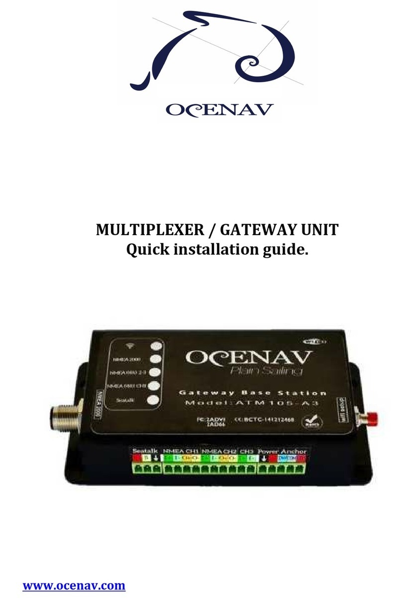
OCENAV ATM105A1N User manual

OCENAV ATM105A1N/2/3, ATM200
1
OCENAV ATM105A1N/2/3–MULTIPLEXER GATEWAYS and
ATM200- ATALOGGER (V2.xx)
Contents
1. General operation: ............................................................................. 2
1.1- Protocols and Input / Output channels: ...................................... 3
1.2- Data input filtering: ............................................................................. 4
1.3- Calculation of the “Perfor ance” data: ....................................... 6
1.4- Output data filtering: .......................................................................... 7
1.5- Data trans ission:............................................................................... 8
1.6- Base station for the re ote control: ............................................. 8
1.7- Alar s center: ....................................................................................... 9
1.8- Datalogger: (ATM200) .................................................................... 10
2. Before you install the device: ...................................................... 12
3. Installation: ....................................................................................... 15
4. Wifi, NMEA183 and NMEA2000 Configuration: .................... 17
5. Software updates:............................................................................ 19
6. Technical data: ................................................................................. 19

OCENAV ATM105A1N/2/3, ATM200
2
1. General operation:
The ATM105A1N / 2/3 and ATM200 are triple protocol gateways
and operate in real ti e following the following process:
1) Reception of the data sent by the navigation instru ents in
any protocol (NMEA0183, NMEA2000 and Seatalk ™) in the
physical input channels (NMEA0183_CH1 to CH3,
NMEA0183_WiFi, CANBUS and Seatalk ™ network).
2) Except for ATM105A1N, radio reception of re ote control
co ands for autopilot.
3) Filtering of this infor ation according to its nature and
supervision in order to establish priority orders,
identification of the type of pilot and to establish the validity
ti es for the data.
4) Fro the pri ary infor ation, execution of calculations to
generate "perfor ance" data, such as real and geographical
wind, drift intensity and direction, VMG, VMC, etc.
5) Alar s control and activation / deactivation.
6) Data filtering before being sent to avoid saturation and loops
on each output channel.
7) Generation of related sentences in all protocols and sending
to the output channels, to the pilot and to the re ote control
ATM105B.
Connectivity:
Up to 6 input channels: 1xSeatalk, wired 3xNMEA0183,
1xNMEA0183 WiFi and 1xNMEA2000. (ATM105A3 /
ATM200)
Up to 5 output channels: 1xSeatalk, wired 2xNMEA0183,
1xNMEA0183 WiFi and 1xNMEA2000. (ATM105A3 /
ATM200)

OCENAV ATM105A1N/2/3, ATM200
3
1.1- Protocols and Input / Output Channels:
1.1.1- Seatalk™: It is a bidirectional channel (input / output)
for ed by 3 wires: Red (+ 12v), Black (Ground, 0v) and
Yellow (Data). All Seatalk devices share the sa e data
line. It works with electric levels of 0 / 12v, with 0 being
the do inant value for collision detection. There is no
aster device or bus anager.
The speed is 4800 bits per second (baud) in
asynchronous 9-bit co unication. It uses blocks of
variable length binary data called datagra s.
More infor ation in:
http://www.tho asknauf.de/seatalk.ht
1.1.2- NMEA0183: It is a text type protocol (Sentences) and
can work on different physical channels: RS232, RS422,
WiFi and Ethernet. In the last two, encapsulation can be
found within TCP / IP or UDP packets.
There can only be one trans itting device on each RS232
/ RS422 channel, but up to 3-4 receivers can be
connected:
The Ocenav gateway units have up to 3 optocoupled
RS422 input channels (receivers) with speeds fro 4800
to 115200 baud, up to 2 output RS422 channels
(trans itters), and a WiFi UDP channel with
independent input / output ports.
The standard speed over RS422 is 4800 baud, reaching
38400 for co unications with AIS.
More infor ation in:

OCENAV ATM105A1N/2/3, ATM200
4
www.plaisance-pratique.co /IMG/pdf/NMEA0183-2.pdf
1.1.3- NMEA2000: Standard IEC61162-3) It is a protocol
derived fro J1939 used in the auto otive industry but
with essages fro arine instru entation.
Its electrical signals are co patible with the "Controller
Area Network" (CAN Bus), consisting of 5 wires: NET+,
NET-, +12v, Ground and Shield. It is a bidirectional bus.
The co unication speed is 250k bits per second.
With the exception of ATM105A2, all OCENAV centrals
have NMEA2000.
More infor ation at:
https://en.wikipedia.org/wiki/NMEA_2000
1.2- ata input filtering:
All OCENAV gateways carry out the following supervision
and control operations:
1.2.1- Bus Protocol. Establish ent of the protocols of
connection and identification with the rest of the
equip ent.
NMEA2000 Identification “Iso Address Clai ”: Bridge
device with initial address: 49 and auto atic change if
there is another device with the sa e address. “PGN
Request”: Request for “Iso Address”.
Seatalk Identification: Bridge Device “Bridge”.
NMEA0183 identification according to the type of
sentence: $ II for instru entation, $ GP for GPS, $ EC for
Electronic Chart or navigator, $ AI for AIS sentences.
1.2.2- GNSS and Navigation Priorities. The GPS/GNSS are
constantly onitored. If there is ore than one GPS in
the syste , when a failure of ore than 5 seconds of the

OCENAV ATM105A1N/2/3, ATM200
5
ain GPS, secondary is enabled auto atically., and data
flow is updated. The order of priority is established
based on the HDOP sent by each GPS / GNSS receiver
connected to the gateway, and the lowest value is taken.
The switching is auto atic.
Although it is not advisable to activate navigation
si ultaneously on ore than one device, the order of
priority for the Navigation data is as follows:
1) NMEA2000. (The highest priority)
2) Internal GPS (ATM200 odel).
3) NMEA0183, WiFi.
4) NMEA0183, channel 1.
5) NMEA0183, channel 2.
6) NMEA0183, channel 3.
7) NMEA0183 WiFi.
8) Seatalk. (The lowest priority).
1.2.3- Validity time control. The validity ti e of vital data for
navigation is controlled.
The ti e for GPS data is 15 seconds.
The ti e for the Navigation data is 5 sec.
After these ti es without valid data, the control panel
generates an alar signal.
1.2.4- ata Priority. So e data is prioritized based on its
accuracy. For exa ple, there are 3 Seatalk datagra s for
coordinates: 1 for latitude (0x50), 1 for longitude (0x51),
and 1 lat / Lon (0x58). In the first two, the precision is
1/100 of a inute and in the last, the precision is
1/1000. The syste will read the 1/1000 (0x58) and
ignore the other two.

OCENAV ATM105A1N/2/3, ATM200
6
The sa e is true for log speed, heading error (XTE), and
rudder angle data.
The ATM105A generates agnetic declination if it is not
receiving it fro a GPS device. The user can also force this
calculation by selecting “Generate Magnetic variation
(declination) in the setup.
1.3- Calculation of the "Performance" data:
- The device uses the Declination (internal or received by
any channel) and Deviation to co plete heading data and for
MAG <-> TRUE conversions.
- Translation of wind sentences between the two for ats
MWV and VWR.
- Transfor ation of position sentences: GLL-GGA, heading:
HDG-HDM-HDT and navigation to waypoint: RMB-BWC.
- NMEA0183 data is sent in all possible units: eters / feet /
fatho s, and knots / k h.
- Set and drift calculation if agnetic heading (HDG), speed
through water (STW), COG and SOG are available. The RMB
sentence is co pleted, calculating the VMG on the waypoint.
(NMEA0183 and N2K).
- Calculation of the true wind fro the apparent wind and
the GPS speed. (NMEA0183 and NMEA2000).
- Auto atic generation of STW fro the SOG, if the log
transducer is not connected. (In Seatalk and NMEA2000).
Useful for calculating true wind in Ray arine
instru entation.
- Calculation of the direction and intensity of the geographic
wind TWD, fro the apparent wind AWS, AWA, HDT, COG
and SOG.(Kit eteo needed).
- Calculation of the VMG value of wind (VMC) if it receives
data of speed and direction of the apparent wind and SOG.- --
- The data that nor ally present so e instability are

OCENAV ATM105A1N/2/3, ATM200
7
exponentially averaged to i prove precision and facilitate
reading. (HDG, STW, AWA, AWS, TWA, TWS, TWD, COG, SOG,
Depth ...)
- Optional extension with at ospheric pressure, cabin
te perature and relative hu idity transducers. The
ATM200 odel is originally equipped with a 9-axis
gyroco pass with autocalibration, internal GPS and
eteorological sensors.
1.4- Output data Filtering:
Unlike other existing gateways on the arket, the
ATM105A1N / 2/3 and ATM200 establish a rotating output
sequence that is opti al to avoid both overflow and to
ensure that all data is sent in a short space of ti e. ti e over
slow NMEA0183 channels. (no ore than 1 sec).
These Ocenav gateways li it the frequency of repetitive
type sentences (Heading or COG / SOG, for exa ple)
received fro NMEA2000 between 1 and 4 per second
depending on their priority, since it is a very fast bus
(250,000 bps).
There is no such li itation for security sentences (AIS /
Marpa).
Each channel has its data output filtered with its
corresponding input, eli inating redundancy. In this way,
the data traffic is reduced to the ini u possible, because
only those that are not available on that channel are sent. In
addition, dangerous data loops are eli inated.

OCENAV ATM105A1N/2/3, ATM200
8
1.5- ata transmission:
The data is trans itted in the three protocols towards the
different physical channels. Two exchanges can be linked to
expand and diversify the network:
1.5.1- Gateway via WiFi: The device can be configured as
Access Point (by default) or as a client. In such a way that
it can be connected to another WiFi present in the
installation, and even to another OCENAV central. This
allows to share navigation data wirelessly between 2
distant points of the boat in any of the other channels
and protocols, and / or to add ore equip ent to the
syste .
1.5.2- Seatalk, NMEA2000 or NMEA0183 links:
Two OCENAV gateways can be linked to each other
through any of their BUSES. Seatalk and NMEA2000 can
be used, although channel 2 of NMEA0183 configured to
115200 can also be used to increase speed. In the latter
case, galvanic isolation between the two centrals would
be achieved because they would be optocoupled.
This ethod also allows ore equip ent to be
connected to the syste with ini al wiring.
1.6- Base station for the remote control:
The ATM105A2 / A3 and ATM200 link with the ATM105B
re ote unit, supplying navigation data and generating the
co ands for the autopilot and the anchor windlass. It
Controls the backlight of Seatalk instru entation.
The autopilot detection is auto atic: STxxxx – S artpilot,
Evolution and Sinrad B&G si net autopilots.

OCENAV ATM105A1N/2/3, ATM200
9
1.7- Alarms center:
There is an optional alar odule configurable by the user
through a WEB for sent by the gateway. The available
alar s are:
- Maxi u apparent wind.
- Mini u depth.
- Low quality GPS data. GPS failure.
- Arrival at the waypoint.
- Pass the Waypoint. (perpendicular to the WPT).
- RADAR security ring: MARPA and AIS. User progra able
distances.
- Activation of the dragging alar when the descent of the
anchor is activated for ore than 4 seconds. Deactivation
when raising the anchor. Progra able distance.
- Weather alar . Maxi u variation of at ospheric
pressure per hour, progra able by the user. Pressure /
te perature transducer required.
The alar s are audible (internal and external buzzer with
light) and also visible and audible on the re ote control.
They are canceled by pressing any key on the re ote
control.

OCENAV ATM105A1N/2/3, ATM200
10
1.8- atalogger: (ATM200)
The ATM200 has a socket for icroSD cards. The user can
select the data to be recorded, its frequency and duration of
each data file, by editing the CONF200.txt file present on the
sa e icroSD card:
SAVE_FREQ=15 /
Sa ple interval (seconds)
FILE_TIME=10 / File
Capture Ti e (hours / file)
SAVE_NAV=NO /
Save Navigation Data: XTE, WPT BRG, VMG
SAVE_WIND=NO /
Save Relative and True Wind Data: speed and angle
SAVE_WATER=YES /
Save Depth, Te perature and Speed
SAVE_STEER=YES /
Save M.Heading, Rudder angle, Autopilot angle
SAVE_ATTIT=YES /
Save Rotation speed (deg/sec), Pitch and Roll
SAVE_METEO=NO /
Save Air te p(C), Pressure(Bar), Relative Hu idity(%)
SAVE_AIS=YES /
Save clossest target: MMSI, Distance, Ru b and Speed
SAVE_ENGINE1=NO /
Save RPM, Coolant pressure, te p, Gear, Trans Te p
SAVE_ENGINE2=NO /
Save RPM, Coolant pressure, te p, Gear, Trans Te p
The files created are of type .CSV co patible with Excel, and
their na es correspond to the UTC date and ti e of creation
for better identification.
SAVE_FREQ is the ti e between captures in seconds.
(Reco ended values: 10-15 seconds).
When the ti e of a file (FILE_TIME) runs out, another file
with a new na e is opened and recording continues until
the equip ent is turned off.
Each file will contain a nu ber of captures equal to
(FILE_TIME * 3600) / SAVE_FREQ. In the exa ple: 10 *
3600/15 = 2400 lines.
The syste filters the AIS data in such a way that only the
data of the closest “target” is recorded in the interval of each

OCENAV ATM105A1N/2/3, ATM200
11
capture within a radius of 0.5 iles and that exceeds the
speed of 0.5 knots.
Exa ple. The following block of data is part of a file created
to track approaching ships while in port. Only AIS and
ATTITUDE data recording has been activated:

OCENAV ATM105A1N/2/3, ATM200
12
2. Before you install the device:
It is very i portant that before installing, the cables and
connection points of the instru ents to be connected are
located, the feasibility of passing the necessary cables through
the ship is studied, and all this is clearly drawn in a diagra . In
this way it will be possible to deter ine where the ATM105A
will be ost convenient.
There is no single configuration for the installation, since the
co binations of equip ent that can be connected are infinite,
however, the connection capacity of the chosen ATM105A
gateway ust be considered, taking into account the following:
- All Ocenav Gateways have a Seatalk Bus and only require a
connection at any point in that network (Red / Yellow / Black).
- The ATM105A1N / A3 only require a single connection cable
to the NMEA200 Bus.- Channel 1 of NMEA0183 of the ATM105A,
is usually used to connect the PGS / plotter or ultifunction
screen (input and output), because its speed is usually fixed at
4800 baud.
- NMEA0183 channel 2 and 3 inputs can be low or high speed
NMEA (4800 or 38400 baud). You can also configure the
channel 2 output filter (*), so that this channel sends all the
available infor ation, or only sends the data not present in its
input.
- If you have an ATM105A2 or A3, it is reco ended to connect
NMEA0183 navigation instru ents on channel 2 (wind
equip ent or DSC radio), since they nor ally require
infor ation fro the rest of the instru entation such as log,
GPS, etc. for speed calculations and true wind angle, VMG, or
position if connecting a radio.

OCENAV ATM105A1N/2/3, ATM200
13
- The AIS receivers can connect to the NMEA2000 Bus or in the
channels IN3 (ATM105A2 / A3) - autobaud, or NMEA0183 IN2
(ATM105A1) changing the speed of NMEA0183 to 38400
(Config. WiFi).-AIS infor ation will be sent via WiFi and
optionally via NMEA2000 and NMEA0183 channel 2, configured
at 38400 baud or higher, since the low speed NMEA0183
outputs do not allow such data volu e. If the AIS is connected to
NMEA2000, the VDM sentences are also reverse translated fro
N2K to NMEA0183 (WiFi and Channel 2 to 38400) (*).
- The ATM105A2 and A3 versions have relay outputs for
controlling the anchor windlass fro the ATM105B re ote.
These outputs are connected at the sa e points on the relay box
as the deck footswitches.
- To drastically reduce cabling and eli inate data redundancy, it
is reco ended that all instru ents be interconnected through
the PBX. This also i proves co unication perfor ance.
Never install more than one gateway in the system attached
to same buses, if you have another converter, uninstall it.
(*) NMEA0183 output channel 2 is not available on the
ATM105A1N odel.

OCENAV ATM105A1N/2/3, ATM200
14
- It is possible to eli inate the existing NMEA0183 cable
between the GPS and an STxxxx or S artPilot S2 / S3 pilot,
since the ATM105 translates the sentences fro NMEA to
Seatalk and vice versa. This cable can be reconnected to the
pilot's Seatalk socket in order to bring Seatalk infor ation to
the ATM105A, without the need to run a new cable through the
boat:

OCENAV ATM105A1N/2/3, ATM200
15
3. Installation:
In order to ensure correct operation and avoid possible
breakdowns, it is recommended that the installation be
carried out by a specialized installer, otherwise, any
responsibility is declined.
- This device ust be screwed to a vertical base, with the
connections at the botto , in a place free of condensation, at a
ini u height of 1 above the floating level and outside of
etal enclosures or surrounded by cables.
- Power: The Power (+/-) socket will be connected to a voltage
source between 8 and 28 volts. It does not require an external
fuse, since the ATM105A is internally provided with an
electronic fuse with auto atic reset. Power connection is not
required if the equip ent is connected to NMEA2000.
- Seatalk: Connect the red, yellow and black cables of the bus to
the Seatalk socket of the equip ent, respecting the colors.
Due to its low consu ption, the ATM105A can be powered by
the Seatalk bus, connecting the (Power +) socket to the Seatalk
(+) socket.
- NMEA2000: Connect the gateway through a drop cable or
branch cable, or using a adaptor cable NMEA2000 to Si net or
SeatlkNG, never directly to the ain bus.
- ANCHOR: Connect the outputs (COM, UP and DW) to the
windlass relay box, in the sa e contacts of the anual buttons:
(COMMON, UP and DOWN). It is very i portant to check that
there is correspondence (raise / lower anchor) between the
anual or foot buttons and the buttons of the ATM105A re ote
control.

OCENAV ATM105A1N/2/3, ATM200
16
The connections between this device and the instru ents with
differential inputs / outputs (RS422) are ade directly: the
instru ent outputs (+ or A), (- or B) are connected to the
ATM105A inputs (+ or A with + , and - or B with -). In the sa e
way, the instru ent inputs with the ATM10A outputs:
Si se conecta un instru ento con salida unipolar (RS232) a una
entrada del ATM105A, la salida de ese instru ento se conectará
a la entrada NMEA+, y la entrada NMEA- se conectará a asa:

OCENAV ATM105A1N/2/3, ATM200
17
Very important: An instrument with unipolar input (RS232)
must be connected only to the NMEA0183 (O +) output of
the ATM105A, leaving the NMEA0183 (O-) output of the
ATM105A unconnected. Otherwise, said output (O-) could
be damaged:
4. Wifi, NMEA183 and NMEA2000 Configuration:
1) Press and hold the red button (Wifi setup) for about 15 seconds
during the start-up of the equip ent. Release the button when
you see the Seatalk LED turn purple.
2) If your S artphone or tablet has an internet connection through
a data network, te porarily deactivate it and activate only the
WiFi connection.
3) Connect to the OCENAVxxxxx WiFi network using the initial
password of the equip ent. These values (Network na e and
password) do not change to enter the configuration even if the
user has odified the for nor al use of the gateway.
4) Use an internet browser to access the ho e page
www.ocenav.co . Usually appears as a popup window. If you
have proble s with access, clear your browser history.
5) On the ho e page, press “Change configuration” to access the
configuration for :

OCENAV ATM105A1N/2/3, ATM200
18
The default para eters* are:
Device in Access Point ode (AP).
SSID (Access Point Na e): OCENAVxxxxx
Access Point Password: at 105xxx
Connetion ode: UDP broadcast / ulticast
UDP address: 45.0.20.1
UDP Port (device): 1433
UDP Port (host): 2433
Notes (*): All these values are odifiable by the user.At this point,
you will be able to change your WiFi network na e, password, IP
address, and the NMEA0183 data input and output UDP ports of the
wireless network.
So e obile applications use port 10110 as the standard for
NMEA0183 data. You can configure both the "device" and the "host"
port with this value.
If you are using Navionics Boating, you ust change port 1433 to
port 2000. In this case, all other apps that you use ust also change
to port 2000.
To connect two ATM105A units to each other, it is necessary to
configure one of the as a client, entering the sa e na e and
password of the gateway as the Access Point, so that that client base
can link with the ain base. In this case, it is reco ended to clear
the value of the "IP" field so that the ain base dyna ically assigns
the address of the client base (HDCP ode).
On this page, you can select different speed and data processing
options for NMEA0183 and NMEA2000 channels. See the WiFi
configuration anual for ore details.
https://ocenav.co /en/user- anual/

OCENAV ATM105A1N/2/3, ATM200
19
5. Software updates:
The ATM105A fir ware can be updated via WiFi fro a
S artphone, tablet or PC, without re oving it fro its location
and using a Web browser (Chro e for exa ple).
It is reco ended that this operation be carried out by an
authorized installer, or failing that, that the user register with
OCENAV by sending an e ail providing the serial nu ber and
installed version. OCENAV will not assu e any responsibility
otherwise.
In the download area of our website you can obtain the
ATM105update.zip file that contains the instructions and the
updated software (.bin).
IMPORTANT NOTE: This update is only possible fro version
1.30. If the equip ent has a previous version installed, it will be
necessary to send it to the after-sales service for its first update.
Please help us i prove: If you have any suggestions, please do
you will be able to collaborate in i proving or expanding the
characteristics of this device.
6. Technical data:
Power supply: 8-29V DC, internal rear able fuse.
Máxi u current: ATM105A1N: 1W (80 A at 12,5V)
ATM105A2/3: 1,2W (90 A at 12,5V)
ATM115: 1W (Without GNSS)
ATM115/200: 1,5W (120 A at 12,5v)
NMEA2000: LEN = 2. ATM200: LEN=3

OCENAV ATM105A1N/2/3, ATM200
20
Maxi u current through NMEA0183 inputs: 5 A
Maxi u current supplied by NMEA0183 outputs: 15 A
Maxi u current of ANCHOR outputs: 1A.
WIFI: 802.11 b / g / n protocol, power: 10, 15 and 20 dB.
Co plete transceiver (trans ission and reception) 100%
co patible with Seatalk, NMEA0183 and NMEA2000.
Radio for co unication with the ATM105B re ote control: 2.4
Ghz, + 20dB
NMEA0183 on reception: versions 2.x to 4.10, LRC check if
received. In trans ission: version 3.01 and 4.10, with LRC
CPU section:
ATM105A1N, 2 processors:
Host processor: ARM Cortex M3 at 72Mhz, WiFi processor:
Tensilica Xtensa LX106 80 MHz.
ATM105A2/A3, 3 processors:
Host Processor: ARM Cortex M3 at 72Mhz, Tensilica Xtensa LX106
80 MHz. and processor for radio Nrf24l01.
ATM115 gyro, Up to 4 processors:
Host Processor: ARM Cortex M3 at 72Mhz, Tensilica Xtensa LX106
80 MHz. and gyroco pass with ARM Cortex M0+ a 32Mhz. optional
GNSS NEO-M8N.
ATM200 datalogger,Up to 5 processors:
Host Processor ARM Cortex M4 at 144Mhz, Tensilica Xtensa LX106
80 MHz., Nrf24l01 and GPS NEO-M8N. Optional Gyroco pass with
ARM Cortex M0+ at 32Mhz.
Real ti e ultitasking operating syste FreeRTOS V10.0 and
FATFS (File Syste ) in the odel ATM200.
This manual suits for next models
2
Table of contents
Other OCENAV Multiplexer manuals