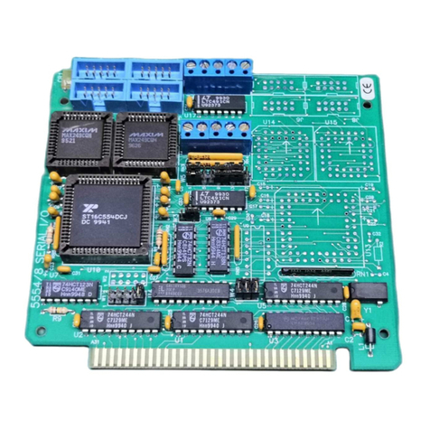
Octagon 5025A User manual

5025A
User’s Manual
Doc. #03999 Rev 1098
OCTAGON SYSTEMS CORPORATION®
6510 W. 91st Ave. Westminster, CO 80030
Tech. Support: 3034264521
StockCheck.com

COPYRIGHT
Copyright 1992–95, 1998—Octagon Systems Corporation. All
rights reserved. However, any part of this document may be
reproduced, provided that Octagon Systems Corporation is cited as
the source. The contents of this manual and the specifications
herein may change without notice.
TRADEMARKS
Micro PC, PC SmartLink, Octagon Systems Corporation®, the
Octagon logo and the Micro PC logo are trademarks of Octagon
Systems Corporation. QuickBASIC® is a registered trademark of
Microsoft Corporation. ROM-DOSis a trademark of Datalight.
SmartSocketand SmartWatchare trademarks of Dallas
Semiconductor.
NOTICE TO USER
The information contained in this manual is believed to be correct.
However, Octagon assumes no responsibility for any of the circuits
described herein, conveys no license under any patent or other
right, and makes no representations that the circuits are free from
patent infringement. Octagon makes no representation or war-
ranty that such applications will be suitable for the use specified
without further testing or modification.
Octagon Systems Corporation general policy does not recommend
the use of its products in life support applications where the
failure or malfunction of a component may directly threaten life or
injury. It is a Condition of Sale that the user of Octagon products
in life support applications assumes all the risk of such use and
indemnifies Octagon against all damage.
StockCheck.com

Using CMOS Circuitry – 1
IMPORTANT!
Please read before installing your product.
Octagon's products are designed to be high in performance while
consuming very little power. In order to maintain this advantage,
CMOS circuitry is used.
CMOS chips have specific needs and some special requirements
that the user must be aware of. Read the following to help avoid
damage to your card from the use of CMOS chips.
StockCheck.com

Using CMOS Circuitry – 2
Using CMOS Circuitry in Industrial Control
Industrial computers originally used LSTTL circuits. Because
many PC components are used in laptop computers, IC manufac-
turers are exclusively using CMOS technology. Both TTL and
CMOS have failure mechanisms, but they are different. This
section describes some of the common failures which are common
to all manufacturers of CMOS equipment. However, much of the
information has been put in the context of the Micro PC.
Octagon has developed a reliable database of customer-induced,
field failures. The average MTBF of Micro PC cards exceeds
11 years, yet there are failures. Most failures have been identified
as customer-induced, but there is a small percentage that cannot
be identified. As expected, virtually all the failures occur when
bringing up the first system. On subsequent systems, the failure
rate drops dramatically.
■Approximately 20% of the returned cards are problem-free.
These cards, typically, have the wrong jumper settings or the
customer has problems with the software. This causes
frustration for the customer and incurs a testing charge from
Octagon.
■Of the remaining 80% of the cards, 90% of these cards fail due
to customer misuse and accident. Customers often cannot
pinpoint the cause of the misuse.
■Therefore, 72% of the returned cards are damaged through
some type of misuse. Of the remaining 8%, Octagon is unable
to determine the cause of the failure and repairs these cards at
no charge if they are under warranty.
The most common failures on CPU cards are over voltage of the
power supply, static discharge, and damage to the serial and
parallel ports. On expansion cards, the most common failures are
static discharge, over voltage of inputs, over current of outputs,
and misuse of the CMOS circuitry with regards to power supply
sequencing. In the case of the video cards, the most common
failure is to miswire the card to the flat panel display. Miswiring
can damage both the card and an expensive display.
■Multiple component failures - The chance of a random
component failure is very rare since the average MTBF of an
Octagon card is greater than 11 years. In a 7 year study,
StockCheck.com

Using CMOS Circuitry – 3
Octagon has never found a single case where multiple IC
failures were not caused by misuse or accident. It is very
probable that multiple component failures indicate that they
were user-induced.
■Testing “dead” cards - For a card that is “completely
nonfunctional”, there is a simple test to determine accidental
over voltage, reverse voltage or other “forced” current
situations. Unplug the card from the bus and remove all
cables. Using an ordinary digital ohmmeter on the 2,000 ohm
scale, measure the resistance between power and ground.
Record this number. Reverse the ohmmeter leads and
measure the resistance again. If the ratio of the resistances is
2:1 or greater, fault conditions most likely have occurred. A
common cause is miswiring the power supply.
■Improper power causes catastrophic failure - If a card
has had reverse polarity or high voltage applied, replacing a
failed component is not an adequate fix. Other components
probably have been partially damaged or a failure mechanism
has been induced. Therefore, a failure will probably occur in
the future. For such cards, Octagon highly recommends that
these cards be replaced.
■Other over-voltage symptoms - In over-voltage situations,
the programmable logic devices, EPROMs and CPU chips,
usually fail in this order. The failed device may be hot to the
touch. It is usually the case that only one IC will be
overheated at a time.
■Power sequencing - The major failure of I/O chips is caused
by the external application of input voltage while the Micro PC
power is off. If you apply 5V to the input of a TTL chip with
the power off, nothing will happen. Applying a 5V input to a
CMOS card will cause the current to flow through the input
and out the 5V power pin. This current attempts to power up
the card. Most inputs are rated at 25 mA maximum. When
this is exceeded, the chip may be damaged.
■Failure on power-up - Even when there is not enough
current to destroy an input described above, the chip may be
destroyed when the power to the card is applied. This is due
to the fact that the input current biases the IC so that it acts
as a forward biased diode on power-up. This type of failure is
typical on serial interface chips.
StockCheck.com

Using CMOS Circuitry – 4
■Serial and parallel - Customers sometimes connect the serial
and printer devices to the Micro PC while the power is off.
This can cause the failure mentioned in the above section,
Failure upon power-up. Even if they are connected with the
Micro PC on, there can be another failure mechanism. Some
serial and printer devices do not share the same power (AC)
grounding. The leakage can cause the serial or parallel signals
to be 20-40V above the Micro PC ground, thus, damaging the
ports as they are plugged in. This would not be a problem if
the ground pin is connected first, but there is no guarantee of
this. Damage to the printer port chip will cause the serial
ports to fail as they share the same chip.
■Hot insertion - Plugging cards into the card cage with the
power on will usually not cause a problem. (Octagon urges
that you do not do this!) However, the card may be dam-
aged if the right sequence of pins contacts as the card is
pushed into the socket. This usually damages bus driver chips
and they may become hot when the power is applied. This is
one of the most common failures of expansion cards.
■Using desktop PC power supplies - Occasionally, a cus-
tomer will use a regular desktop PC power supply when
bringing up a system. Most of these are rated at 5V at 20A or
more. Switching supplies usually require a 20% load to
operate properly. This means 4A or more. Since a typical
Micro PC system takes less than 2A, the supply does not
regulate properly. Customers have reported that the output
can drift up to 7V and/or with 7-8V voltage spikes. Unless a
scope is connected, you may not see these transients.
■Terminated backplanes - Some customers try to use Micro
PC cards in backplanes that have resistor/capacitor termina-
tion networks. CMOS cards cannot be used with termination
networks. Generally, the cards will function erratically or the
bus drivers may fail due to excessive output currents.
■Excessive signal lead lengths - Another source of failure
that was identified years ago at Octagon was excessive lead
lengths on digital inputs. Long leads act as an antenna to pick
up noise. They can also act as unterminated transmission
lines. When 5V is switch onto a line, it creates a transient
waveform. Octagon has seen submicrosecond pulses of 8V or
more. The solution is to place a capacitor, for example 0.1 µF,
across the switch contact. This will also eliminate radio
frequency and other high frequency pickup.
StockCheck.com

iii
TABLE OF CONTENTS
PREFACE.........................................................................1
Conventions Used in This Manual .................................................... 1
Symbols and Terminology .................................................................. 2
Technical Support ............................................................................... 4
CHAPTER 1: OVERVIEW ............................................... 5
Description .......................................................................................... 5
Major Features .................................................................................... 5
Where to go from here: ....................................................................... 8
CHAPTER 2: QUICK START........................................11
Hardware Installation ...................................................................... 11
Panel Mounting the 5025A........................................................ 11
Using a Micro PC Card Cage .................................................... 13
Establishing Communications with the 5025A .............................. 16
Transferring Files between 5025A & Your PC ............................... 18
Downloading Files to the 5025A ............................................... 18
CHAPTER 3: RAMS AND EPROMS ............................21
SSD1................................................................................................... 21
To Install an EPROM ................................................................ 21
SSD2................................................................................................... 22
To Install an EPROM ................................................................ 22
To Install Static RAMs .............................................................. 23
To Install Battery Backup for SSD2 ........................................ 23
CHAPTER 4: SETUP ....................................................25
Description ........................................................................................ 25
Running SETUP ................................................................................ 26
SETUP Example ............................................................................... 30
CHAPTER 5: SAVE & RUN PROGRAMS....................31
Save and Run Your Programs on the 5025A .................................. 31
Saving Program and Support Files ................................................. 31
Autoexecuting Your Program ........................................................... 34
Overriding Program Autoexecution from SSD1 ............................. 34
StockCheck.com

iv
Running SETUP Again.............................................................. 35
Removing Jumper W3[3–4] ....................................................... 35
CHAPTER 6: SERIAL PORTS......................................37
Description ........................................................................................ 37
COM1 as Console I/O........................................................................ 38
COM1 as RS-232 I/O......................................................................... 39
COM2 as RS-422/485 I/O.................................................................. 39
Operating Precautions............................................................... 41
Transmitter Control .................................................................. 42
Termination Network ................................................................ 42
Disabling Interrupts ......................................................................... 43
Using QuickBASIC to Communicate via COM1 ............................ 43
Systems with a Video Card ....................................................... 43
Systems without a Video Card ................................................. 43
Using Turbo C ............................................................................ 45
CHAPTER 7: WATCHDOG TIMER...............................47
Description ........................................................................................ 47
CHAPTER 8: LPT1 PRINTER PORT............................49
Description ........................................................................................ 49
Printer................................................................................................ 50
Display ............................................................................................... 50
Keypad ............................................................................................... 51
Digital I/O Lines................................................................................ 51
CHAPTER 9: SERIAL EEPROM ..................................53
Description ........................................................................................ 53
Reading the Serial EEPROM ........................................................... 53
Writing to the Serial EEPROM ....................................................... 53
CHAPTER 10: VIDEO AND KEYBOARD....................55
Description ........................................................................................ 55
Using a Video Monitor and Keyboard ............................................. 55
Saving a Program to the 5025A ................................................ 56
StockCheck.com

v
Transferring Files to the 5025A ............................................... 57
Transferring Files from the 5025A........................................... 58
CHAPTER 11: EXTERNAL DRIVES ............................59
Description ........................................................................................ 59
Floppy Disk Drives ........................................................................... 59
Hard Disk Drive................................................................................ 60
CHAPTER 12: USING YOUR OWN DOS/OS ..............63
Description ........................................................................................ 63
Getting Started ................................................................................. 63
Selecting Boot, Memory, and Drive Options................................... 64
Booting the 5025A from a Floppy/Hard Disk Drive................ 64
Booting from SSD1 with/without a Floppy Drive ................... 65
CHAPTER 13: USER-DEFINED JUMPER ...................67
CHAPTER 14: CPU POWER MANAGEMENT.............69
Description ........................................................................................ 69
SLEEP.COM ...................................................................................... 69
SLOW.COM ....................................................................................... 70
Implementation ................................................................................. 70
Advanced Power Management TSR ................................................ 70
CHAPTER 15: TROUBLESHOOTING...........................71
Technical Assistance......................................................................... 73
CHAPTER 16: TECHNICAL DATA...............................75
Technical Specifications ................................................................... 75
Interrupts .......................................................................................... 79
Jumper Settings ................................................................................ 79
Connector Pinouts ............................................................................. 83
PC Bus Pinouts.................................................................................. 85
StockCheck.com

vi
APPENDIX A ..................................................................87
Introduction ....................................................................................... 87
COM1CON.COM............................................................................... 88
DISKSAVE.EXE................................................................................ 89
DISKSEND.EXE ............................................................................... 92
FAST.COM ........................................................................................ 94
LPT1CON.COM ................................................................................ 95
MEMDRIVE.SYS .............................................................................. 96
RESET.COM...................................................................................... 99
SETUP.COM ................................................................................... 100
SLEEP.COM.................................................................................... 102
SLOW.COM ..................................................................................... 103
TRANSFER.EXE............................................................................. 104
APPENDIX B ................................................................107
Programming Standard EPROMs ................................................. 107
Custom Communication Cable....................................................... 107
Power Supply................................................................................... 108
Uploading Files from the 5025A .................................................... 108
Assigning Drive Designators.......................................................... 109
Example: ................................................................................... 110
Extended Memory ........................................................................... 110
Interrupts ........................................................................................ 112
Using Microsoft Windows 3.1 ........................................................ 113
WARRANTY
StockCheck.com

Preface – 1
PREFACE
This manual provides all the information required to install,
configure, and operate the 5025A Micro PC Control Card. It is
part of Octagon’s Micro PC user manual series. To receive the
Micro PC User Manual Binder, please return the reply card
included with your Control Card.
By using this manual, you will be able to:
• Interface the 5025A Control Card to your PC and the Micro PC
expansion cards.
• Set up communications between the 5025A card and a PC.
• Gain an understanding of the operation and various options
allowed in the 5025A Control Card.
CONVENTIONS USED IN THIS MANUAL
1. Information which appears on your screen (output from your
system, commands or data that you key in) is shown in a
different type face.
Octagon 5025A-486-25MHz-2MB BIOS Vers x.xx
Copyright (c) 1992-1994 Octagon Systems Corp. (TM)
All Rights Reserved.
2. Italicized refers to information that is specific to your particu-
lar system or program, e.g.,
Enter filename
means enter the name of your file.
3. Warnings always appear in this format:
The warning message appears here.
4. Paired angle brackets are used to indicate a specific key on
your keyboard, e.g., <ESC> means the escape key; <CTRL>
means the control key; <F1> means the F1 function key.
5. All addresses are given in hexadecimal.
WARNING:
StockCheck.com

Preface – 2
SYMBOLS AND TERMINOLOGY
Throughout this manual, the following symbols and terminology
are used:
W[ – ] Denotes a jumper block and the pins to
connect.
Autoexecution Automatic execution of a program on power–
up or reset.
BIOS drive The solid–state disk which contains the
system BIOS and ROM–DOS.
Console Port Video card or COM1 where BIOS and DOS
messages appear and keyboard input is
available.
Control Card Contains the CPU, memory, and operating
system and controls the operation of all the
extension cards.
DRAM Dynamic Random Access Memory devices.
DRAMs provide volatile memory with
unlimited read and write cycles.
Expansion Card The expansion cards add I/O functions to the
Micro PC system, such as analog input/
output, digital input/output, motion control,
display, and so on.
Flash memory Electrically erasable EPROM which allows
approximately 10,000 writes.
Memory device The type of static RAM, DRAM, flash memory
or EPROM specified for either volatile or
nonvolatile memory.
PC SmartLINK A serial communications software package
designed by Octagon for use with the 5025A
Control Card. Refers to all versions of PC
SmartLINK.
StockCheck.com

Preface – 3
ROM Read Only Memory devices. ROMs provide
nonvolatile memory, have a limited number of
write cycles, and include EPROMs,
EEPROMs, and flash memory.
ROM–DOS DOS operating system included in Micro PC
ROM.
Solid–State Disk A simulated disk using a high speed solid–
(SSD) state memory device, for example flash
memory, EEPROM, or static RAM.
Static RAM Static Random Access Memory device. Static
RAMs provide volatile memory with unlim-
ited read and write cycles. They may be used
with a battery back–up module.
TTL Compatible Transistor transistor logic compatible; 0–5V
logic levels.
Virtual Drive A disk created in DOS or extended memory
which emulates an actual disk. Provides
temporary storage for files. When power to
the computer is turned off the virtual drive
disappears.
XMODEM A communications protocol which allows
transfer of files between two computers.
XON/XOFF A communications protocol for asynchronous
connections. The receiver can pace the sender
by sending the XOFF and XON characters to
stop and continue the data flow.
H The suffix “H” denotes a hexadecimal num-
ber. A decimal number has no prefix or
suffix. For example, 1000H and 4096 are
equivalent.
StockCheck.com

Preface – 4
TECHNICAL SUPPORT
If you have a question about the 5025A Control Card and cannot
find the answer in this manual, call Technical Support. They will
be ready to give you the assistance you need.
When you call, please have the following at hand:
Your 5025A Control Card User’s Manual
A description of your problem.
The direct line to Technical Support is 303–426–4521.
StockCheck.com

Overview – 5
CHAPTER 1 OVERVIEW
DESCRIPTION
The 5025A PC Control Card is designed for use with Octagon’s
Micro PC system. This system uses small computer cards –
4.5 in. x 4.9 in. Its small size, wide temperature range (–40°C to
+85°C) and rugged CMOS construction, make it ideal for high
performance, embedded control applications. It has COM1 and
COM2 serial ports, LPT1 parallel port, a keyboard and speaker
port, calendar/clock, watchdog timer, up to 8 MB of DRAM, DOS in
ROM, coprocessor socket, and three solid–state disks. The 5V
operation simplifies installation. You program the card either
through the serial port from your PC, or by adding a keyboard,
monitor and floppy drive.
Three versions are available: the 5025A-386-25MHz, which has a
80386SX CPU; the high performance 5025A-486-25MHz, which has
twice the performance of the 5025A-386-25MHz (it uses the code
efficient 80486SLC CPU from Cyrix or Texas Instruments); and the
5025A-486-50MHz, which has a 50 MHz 80486SLC2 (internal clock
doubler) with internal cache memory. The 5025A-486-50MHz
internal CPU processing occurs at 50 MHz while local bus process-
ing occurs at 25 MHz. This allows the 5025A-486-50MHz to run
about 80 percent faster than the 5025A-486-25MHz. Bus master-
ing is not supported on the 5025A.
MAJOR FEATURES
ROM–DOS Operating System
The 5025A is an “instant DOS” system. The card includes 6.22
compatible DOS in a solid–state disk. If you wish to use your own
operating system, you may install it in SSD1 with your application.
The system boots and operates the same way as your desktop PC.
During run time it requires only about 64K of RAM space if ROM
DOS is loaded low, or 20K if ROM DOS is loaded high.
Watchdog Timer
The watchdog timer is used to reset the system if the program
stops unexpectedly. The watchdog is enabled under software
control. The timeout is jumper selectable for 150 mS, 600 mS or
1.2 seconds.
Battery Backup and Calendar/Clock Option
The 5025A has a built–in, AT style calendar/clock. An external
3.6V AT clock battery plugs into the card, which powers the clock
during power–down.
StockCheck.com

Overview – 6
Solid–State Disk Options
SSD0 contains the BIOS and DOS 6.22 in the BIOS drive ROM.
SSD1 is used for storage of the applications program. SSD1
accepts either 12V flash memory, 5V flash memory, or standard
EPROMs. (See the list of SSD1 options immediately below.) The
flash memory programmer is built–in allowing reprogramming
through a serial port. SSD1 is described in further detail in the
RAMs and EPROMs chapter.
SSD1 options include:
128K 12V flash
256K 12V flash
128K 5V flash
512K 5V flash
512K EPROM
1 MB EPROM
SSD2 is used primarily for logging process data. SSD2 accepts
static RAMs, 5V flash memory, or standard EPROMs. (See the list
of SSD2 options immediately below.) The static RAM can be
battery–backed with a DS–1213DM battery backup module or the
external 3.6V AT clock battery. SSD2 is described in further detail
in the RAMs and EPROMs chapter.
SSD2 options include:
128K SRAM
512K SRAM
128K 5V flash
512K 5V flash
512K EPROM
1 MB EPROM
Speaker and Keyboard Port
The speaker and keyboard lines are brought out to a 10–pin
connector via a CMA–10 cable. The Octagon PSKI–1 interface
provides a PC compatible connector for the keyboard and provides
screw terminals for the speaker. Any AT compatible keyboard may
be used. A keyboard and monitor are not required for operation.
The keyboard and monitor can be substituted for a terminal or PC.
StockCheck.com

Overview – 7
Mounting
There are three ways to mount the 5025A:
1. Plug it directly into a Micro PC card cage;
2. Use the optional PC mounting bracket and plug it into any
passive backplane;
3. Panel mount it using the four mounting holes. A screw
terminal connector is used to supply the 5V power.
COM1 and COM2 Serial Ports
The serial ports use a high performance 16C550 communications
controller, which is Intel 8250 compatible. The baud rates are
programmable from 150 to 115K baud. Both ports have a RS–232
interface. RS–232 voltages are generated on–card. COM2 is also
jumperable as RS–422 and RS–485 for multidrop operation.
LPT1 Parallel Port
The parallel printer port can be used to support a number of
devices:
1. PC compatible printer
2. 17 digital I/O lines
3. Matrix keypad
4. Multiline displays
5. Octagon's MPC-16PC Opto I/O Rack
This port has a 20–pin connector. When used only for digital I/O, a
CMA–20 cable connects the port to the STB–20 terminal board for
connection to field wiring. This port will also interface with
Octagon displays and keypads. For LCD displays, use the LCD–
IFB interface board and the DP–IFB interface board for the DP
series (vacuum fluorescent) displays. Both interface boards have
keypad connectors. A CMA–20 cable is required.
Setup stored in EEPROM
The 5025A stores its setup information in nonvolatile EEPROM; as
a result it is immune to battery or power failure. The user can also
store additional information in the EEPROM: Up to 1792 bytes
(that is, 896 words) are available.
80C387SX Math Coprocessor Option
The optional 80C387SX coprocessor (Cyrix CX83S87–25 or Intel
BOX387SX–25) dramatically increases the throughput of numeri-
cal computations in mathematics–intensive operations, thus
removing this activity from the CPU.
StockCheck.com

Overview – 8
Hardware Reset
You can reset the system without turning off the power using the
hardware reset button or the RESET command. It also provides a
more complete reset than the <CTL> <ALT> <DEL> method.
Expansion Cards Available
The 5025A takes one card slot in a Micro PC card cage. Micro PC
expansion cards (e.g., the 5805 Solid–State Disk Card, 5800A
Floppy/Hard Disk Card, etc.) can be used by simply plugging the
expansion card into the backplane of the card cage. Up to seven
expansion cards can be used with the 5025A Control Card.
Differences between the 5025 and the 5025A
The 5025A is an enhanced version of the 5025. Various features of
the 5025 were improved upon to create the 5025A. See the table
below for a list of differences between these products.
Differences Between the 5025 and the 5025A
Features 5025 5025A
Max. DRAM 4 MB 8 MB
SSD0 ROM size 128K 512K
SSD1 - max EPROM 1 MB 1 MB
SSD2 - max flash 256K 512K
SSD2 - max SRAM 1.5 MB 512K
SSD2 - max flash 0K 512K
SSD2 - max EPROM 0K 1 MB
SETUP EEPROM 128 bytes 2048 bytes
DOS version 5.0 6.22
Where to go from here:
Before you can begin developing your application program for the
5025A, we recommend you read Chapters 2–4. These chapters give
instructions for hardware installation, downloading and saving
your program, and autoexecuting your application.
StockCheck.com

Overview – 9
Chapter 2 Covers the basics of setting up
Quick Start a 5025A system. This chapter
describes how to install the 5025A
into the card cage, how to establish a
serial communications link with your
PC and how to download files to the
5025A.
Chapter 3 Configuring and installing static
RAMs & EPROMs RAMs and EPROMs. Installing the
battery backup and calendar/clock
module.
Chapter 4 Running the SETUP configura-
SETUP tion program.
Chapter 5 How to save your program files
Save & Run Programs and autoexecute them from the
5025A.
Chapter 6 Using COM1 and COM2. Setting
Serial Ports COM1 as the main console I/O for
serial communications with your PC.
Chapter 7 Enabling the watchdog timer and
Watchdog Timer configuring the timeouts.
Chapter 8 Using the LPT1 parallel port for a
LPT1 Printer Port printer, digital I/O, display or
keypad.
Chapter 9 How to read and write to the serial
Serial EEPROM EEPROM.
StockCheck.com

Overview – 10
Chapter 10 Configuring the 5025A with video
Video and Keyboard and a keyboard.
Chapter 11 Configuring the 5025A with a floppy
External Drives drive or hard drive.
Chapter 12 Configuring the 5025A with a version
Using Your Own DOS/OS of DOS/OS other than ROM-DOS.
Chapter 13 Configuring the user-defined jumper.
User-Defined Jumper
Chapter 14 Using the SLEEP.COM and
CPU Power SLOW.COM as power management
Management utilities.
Chapter 15 Problems encountered when using
Troubleshooting the 5025A.
Chapter 16 Technical specifications, jumper
Technical Data configurations and connector pinouts.
Appendix A Description and operation of
Software Utilities software utility programs and device
drivers.
Appendix B Using non–Octagon cables, program-
ming EPROMs, uploading files from
the 5025A and assigning drive
designators.
StockCheck.com
Table of contents
Other Octagon Controllers manuals
Popular Controllers manuals by other brands

Twinkly
Twinkly PRO Instruction guide

SOMFY
SOMFY TaHomaPad io Installer manual

Marathon Power
Marathon Power TRTC Series Installation, operation and maintenance manual

Regin
Regin RVAZ4L1-24A Instruction

Danfoss
Danfoss ECL Comfort 310 Mounting guide

Cooper Lighting
Cooper Lighting WaveLinx LVPM-12-100-64-2E quick start guide