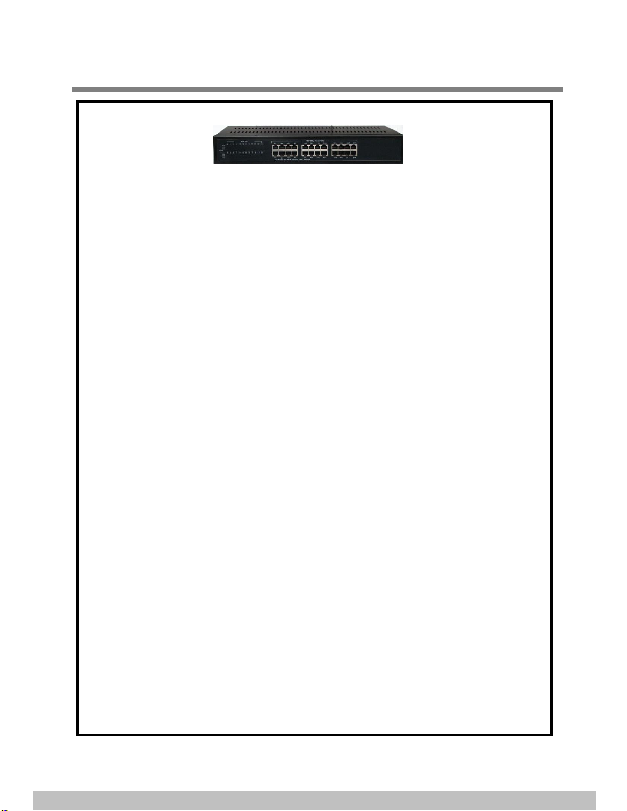
OEM SST-MT-PSW24 User manual

24-Port 10/100M Ethernet PoE Switch-AT Rev 1.0 04/10/2012 Page 1 / 8
IMPORTANT
This users guide contains information on the limitations regarding product use and function and
information on the limitations as to liability of the manufacturer. Read the entire guide carefully
•FCC Warning:
This device has been tested and found to comply with the regulations for Class B digital equipment.Pursuant to Part 15
of FCC Rules. These limits are designed to provide reasonable protection against harmful interference when the
equipment is operated in a commercial environment. This equipment generates, uses, and can radiate radio
frequency energy and, if not installed and used in accordance with users guide, may cause harmful interference to
radio communications. Operation of this devices in a residential area is likely to cause harmful interference, in which
case the user will be required to correct the interference at his/her own expense.
•CE Mark Warning:
This is a Class B product. In a domestic environment, this product may cause radio interference, in which case the user
may be required to take adequate measures.
•UL Warning:
1> Elevated Operating Ambient Temperature- If installed in a closed or multi-unit rack assembly, the operating ambient
temperature of the rack environment may be greater then room ambient. Therefore, Consideration should be given to
installing the equipment in an environment compatible with manufacturer’s maximum rated ambient temperature
2> Reduced Air flow-installation of equipment in a rack should be such that the amount of air flow required for safe
operation of the equipment is not compromised.
3> Mechanical Loading- mounting of the equipment in the rack should be such as that a hazardous
Conditions is not achieved due to uneven mechanical loading.
•Introduction …………………………………………………..
•Power Over Ethernet (PoE) & Features ……..…………..
•Unpacking and Installation ……… .………………………..
•System Requirement……. .………………………………..
•Hardware Installation… …………. …………….……….…..
•Front /Rear Panel /LED….…………………………………
•Connecting Ethernet Cable………………………………….
•Technical Specification……………………………………....
•Troubleshooting ………...……………..……..……………...
Page 2
Page 2
Page 3
Page 3
Page 4
Page 6
Page 7
Page 8
Page 5
Quick Installation Guide
24-Port 10/100M Ethernet PoE Switch (af Version 15.4W)
Table of Contents

1. Introduction
The 24-Ports10/100M Ethernet PoE Switch combines a high efficiency 24-ports 10/100Mbps Ethernet switch and a
standard 802.3af 24-ports Power over Ethernet (PoE) capability. The 24-Ports 10/100M Ethernet PoE Switch
incorporates an internal 48VDC power supply. Each of the PoE Ethernet ports can support 15.4 Watts of power as
well as 10/100M data transmission over the Inter- connecting Ethernet interface such as Cat 5/ 5e /6 cables.
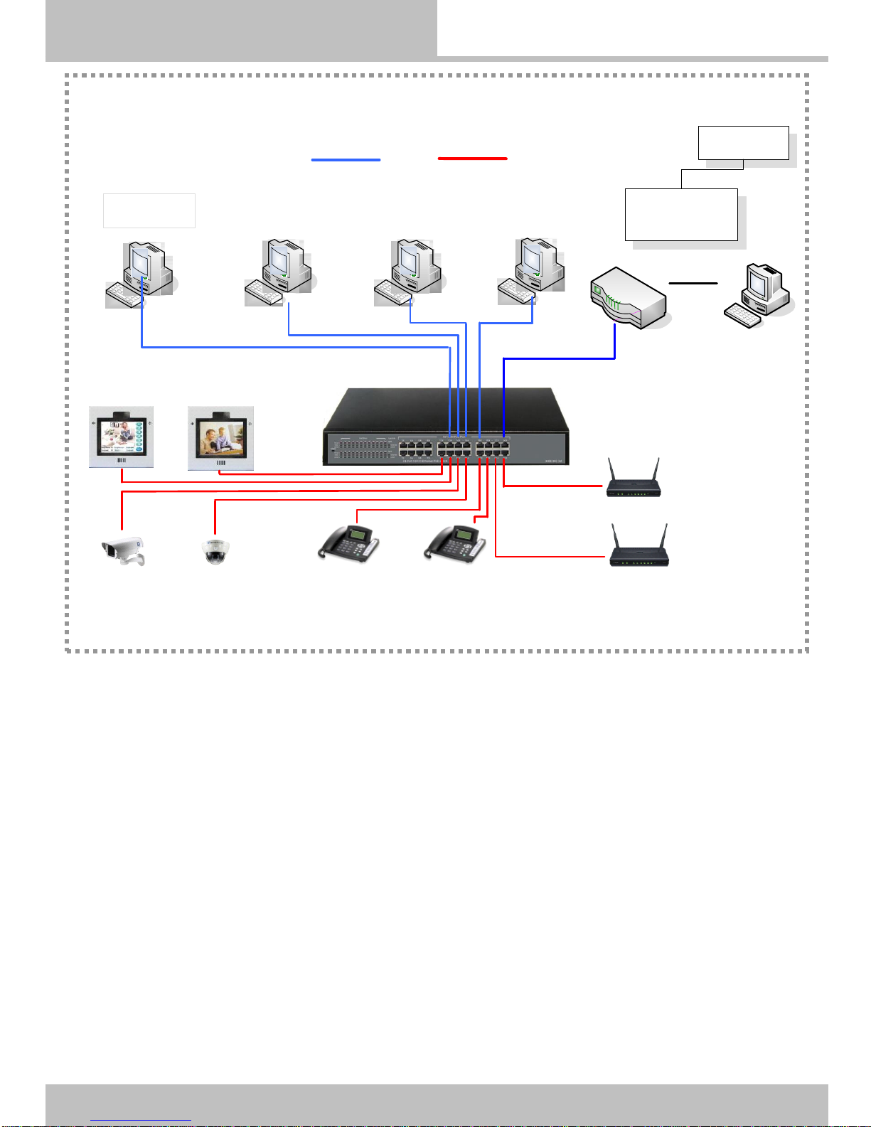
The 24-Ports 10/100M Ethernet PoE Switch is a Power Source Equipment (PSE) and fully compatible with Powered
Devices (PD) that comply with the IEEE 802.3af PoE standard. The 24-Ports 10/100M Ethernet PoE Switch PoE
Switch enables users to attach IEEE802.3af compliant devices such as wireless Access Points (APS), VOIP phone,
IP camera, printer and Network Attached Storage (NAS) directly to the 24-ports 10/100 Ethernet PoE Switch without
requiring additional power on the network. The unit is designed for home and small business users in mind and is ideal
for installations where AC power is not available or no cost-effective.
No configuration is required and installation is quick and easy. Support for Auto –MDI / MDI-X on all of the ports
eliminate the need for crossover connection to another switch or HUB. Auto - Negotiation on each port senses the
link speed of a network device ( either 10 or 100) and intelligently adjusts for compatibility and optimal performance.
* 1-Year Limited Warranty for switch and 1-Year Limited Warranty for the power adaptor are available
* This device is designed for indoor use. Do not use outdoors.
* included are the installation manual.
24-Port 10/100M Ethernet PoE Switch Rev 1.0 04/10/2012 Page 2 / 8
•Power Over Ethernet (PoE):
Power over Ethernet (PoE) integrates 48V power and data onto one single cable, eliminating the need to have
AC power available at all equipment locations. Power and Data are integrated onto the same cable, supporting
category 5/5e up to 100 Meters. PoE provides power to PoE compatible devices, such as VOIP telephones,
wireless LAN access points, and IP security cameras.
PoE device are ready in the market, saving up to 50% of overall installation cost by eliminating the need to install
separate electrical wiring and power outlets.
•Features:
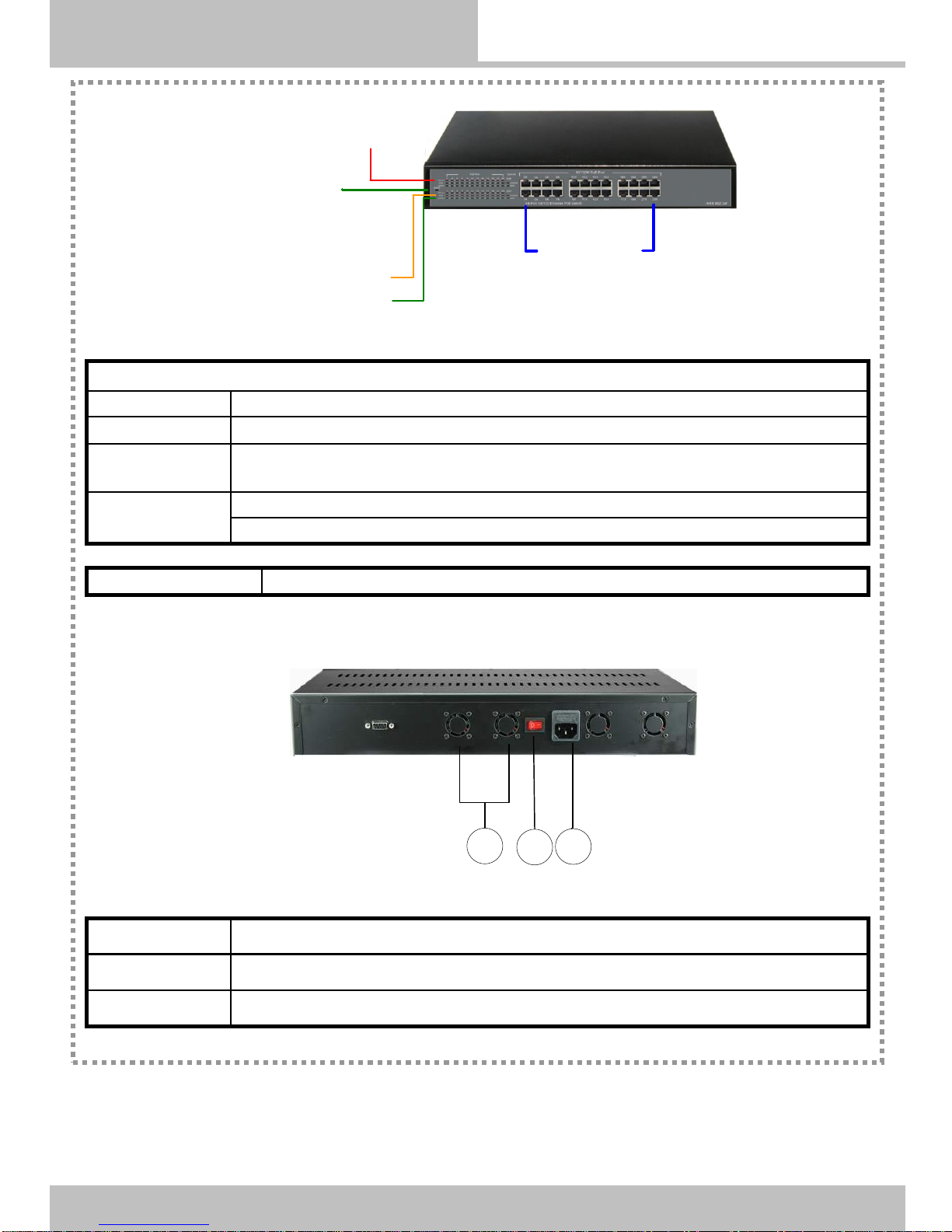
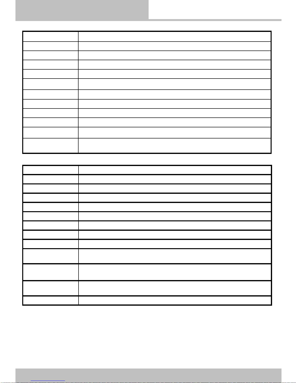
24 x 10/100Mbps Auto-negotiation Fast Ethernet RJ-45 ports with 24-Ports PoE function ( port 1 ~ port 24).
Compliant with IEEE 802.3af(24-Port 10/100M Ethernet PoE Switch).
Supports PoE power up to 340W for all PoE ports.
Supports PoE IEEE802.3af compliant Powered Device (PD)
Each port supports auto MDI/MDIX, so there is no need to use cross-over cables.
Full/half duplex transfer mode for each port.
Wire speed reception and transmission.
Up to 4K unicast address entities per device. Self-learning, and table aging.
64KBytes packet buffer.
2. Power over Ethernet (PoE) & Features

3. Unpacking and Installation
24-Port 10/100M Ethernet PoE Switch/AT Rev 1.0 05/30/2011 Page
Open the received cartons of the 24-ports 10/100 Ethernet PoE Switch and carefully
unpack its contents. The cartons should Included following
items:
One 24-Ports 10/100M Ethernet PoE Switch.
One AC power cord.
Four rubber feet with adhesive backing.
Mounting kit (two brackets and screws)
Quick Installation Guide.
If any item is found missing or damaged,
please contact your local reseller for replacement.
24-Port 10/100M Ethernet PoE Switch Rev 1.0 04/10/2012 Page 3 / 8
•Installation:
The installation of the 24-ports 10/100 Ethernet PoE Switch requires the following steps:
A computer with a 10/100Base-T network adapter installed.
The surface must support at least 6.0Kg (13.2 lbs) for the switch.
The power outlet should be within 1.5 meters (5 feet) of the switch.
Visually inspect the AC power cord and make sure that is fully secured to the power outlet.
Make sure that there is proper heat dissipation from and adequate ventilation around the
switch. Do not place heavy objects on the switch.
4. System Requirements

5. Hardware Installation
A: Connect theAC Power Cord to the 24-Ports 10/100M Ethernet PoE Switch and then to
a power outlet.
24-Port 10/100M Ethernet PoE Switch Rev 1.0 04/10/2012 Page 4 / 8
AC Power Cord
AC power
Outlet
B: Connect a CAT-5, CAT-5e or CAT-6 RJ-45 network cable from the computer to an
available Ethernet port on the 24-Ports 10/100M Ethernet PoE Switch.
C: Installing 24-Ports 10/100M Ethernet PoE Switch on a Desktop:
When installing the 24-Ports 10/100M Ethernet PoE Switch on a desktop or shelf, the
rubber feet Included with the 24-Ports 10/100M Ethernet PoE Switch should first be attached.
Attach these cushioning feet on the bottom at each corner of the device.
D: Installing the 24-Ports 10/100M Ethernet PoE Switch on a 19” Rack:
Fasten the mounting brackets to 24-Ports 10/100M Ethernet PoE Switch using the screws
provided. With the brackets attached securely, you can mount 24-Ports 10/100M Ethernet
PoE Switch series in a standard rack as shown on the following page.

24-Port 10/100M Ethernet PoE Switch Rev 1.0 04/10/2012 Page 5 / 8
Front Panel
6. Front Panel/LED/PoE Network
Rear Panel
1 AC Power Input Outlet: Input 100V~240VAC 2.0A 50-60Hz
2 Power Switch
3 Fan Window
●: Light ☼: Blinking Slowly O: Inactive *: Blinking Fast
Power LED LED on: Power ON / LED off: Power off.
10/100M (1-24) ●: Link for 100Mbps, ☼: Link for 10Mbps.
Act / Link(1-24) ●: Link in full duplex mode and no activity *: Activity ongoing
☼: Link in half duplex mode and no activity O : Link down
PoE (1 to 24) LED on: The PoE power device (PD) is connected and the port is supplying power successfully
LED off: no PoE power device (PD) connected
LED Display
Interface Port
Port 1 -24 PoE 10/100MBase-T Ethernet PoE Port 1 –Port 24. 8P8C RJ-45.
Power LED
PoE ACT LED
Act / Link LED
10/100M LED
10/100M PoE Port
1
2
3

Connecting Ethernet Cables
6. Connecting Ethernet Cables
24-Port 10/100M Ethernet PoE Switch Rev 1.0 04/10/2012 Page 6 / 8
PoE Ethernet Network Diagram
24 Port 10/100M
Ethernet PoE Switch
Data PoE : Data + 48VDC
INTERNET
Broadband Router
100M Cat5/5e/6 cable
PoE Device
PoE VoIP Phone PoE Device
PoE Wireless Access point
PoE Device
PoE IP Camera
PoE Device
PoE Touch Screen
Workstation Workstation

7. Technical Specifications
24-Port 10/100M Ethernet PoE Switch Rev 1.0 04/10/2012 Page 7 / 8
Standard IEEE 802.3 10BASE-T Ethernet
IEEE 802.3u 100BASE-TX Fast Ethernet
IEEE 802.3x Full Duplex Flow Control
IEEE 802.3af Power over Ethernet
Protocol CSMA/CD
Data Transfer Rate Ethernet: 10Mbps (half-duplex), 20Mbps (full-duplex)
Fast Ethernet: 100Mbps (half-duplex), 200Mbps (full-duplex)
Network Cables 10BASE-T: 2-pair UTP Cat 3, 4, 5 up to 100 meters.
100BASE-Tx: 2-pair UTP Cat 5, 5e up to 100 meters.
Number of Ports 24 x 10/100Mbps auto-MDIX RJ-45 ports with 24 PoE enabled ports.
PoE power on RJ-45 Power +: ping 3 & ping 6 : Power –” ping 1 & ping 2
AC to DC power
supply Input: 110V ~ 240VAC, 50Hz ~ 60Hz. Output: 48VDC / 7.3A
Power Consumption 8.0 watts ( max with no PD device connected)
340 watts (23 PoE ports 15.4W/port)
Temperature Operation: 0℃~ 40 ℃or 32℉~ 104 ℉
Storage Temperature: -10℃~ 70 ℃or 14℉~ 158 ℉
Humidity Relative Humidity: 5% - 95%
Dimensions 430mm W x 256mm D x 66.4mm H
EMI FCC Class B, CE Mark Class B
Safety 110VAC to 240VAC power supply UL listed.
RAM buffer 64K bytes per device
Filtering Address
Table 1K entries per device
Packet Filtering
Forwarding Rate 10Mbps Ethernet: 14,880/pps
10Mbps Ethernet: 148,800/pps
MAC address
Learning Automatic update
Transmission Method Store –and –Forward

8. Troubleshooting
24-Port 10/100M Ethernet PoE Switch/AT Rev 1.0 04/10/2012 Page 8 / 8
1> After connecting the Switch to a power outlet, the LEDs do not turn on.
Check the connection of the power cord to the 24-Ports 10/100M Ethernet PoE Switch
and the power outlet.
Check that the power outlet is receiving power.
2> When I connect a computer to the Switch's port, the Link/ACT LED turns on, but
the 100Mbps LED remains off.
When the 100Mbps LED is off, the computer's connection speed is 10Mbps.
3> After I connect my PCs to the Switch, I am unable to share files.
1. Check the LEDs on the Switch. Make sure the Link/ACT LED is on.
2. Check the network cable. The minimum length of the cable is 1.5 meters and the
maximum length of the cable is 100 meters.
3. Disable any software firewall program.
4. Verify that you have file sharing enabled. Please contact your Operating System
support for more information.
4> After I connect my PCs to the Switch, I can only get onto the Internet from one
computer.
The Switch is not designed to share Internet between multiple computers. You need to
get an Internet route.
5> Where is the uplink port located on the Switch?
Since all the ports on the Switch are Auto-MDIX, any of the ports can be used as an
uplink port. If you still encounter problems or have any questions regarding the PoE
switch please contact local Technical Support Department.
Table of contents
Other OEM Switch manuals
Popular Switch manuals by other brands

Altusen
Altusen KM0032 quick start guide

Kindermann
Kindermann MultiSwitch 41 4K60 Mounting and operating instructions

Aurora
Aurora IPX series user guide

3Com
3Com Switches owner's manual

SMC Networks
SMC Networks EZ Networking SMC-EZ108FDT Specification sheet

3One data
3One data IES206 Series Quick installation guide