Oerlikon Fairfield Torque-Hub C014C5 Series User manual

1
Torque-Hub®Planetary Final Drive
C014C5 Series Service Manual
Rev 01/11/13

2
While every precaution has been taken in the preparation of this document, Fairfield Manufacturing Co. Inc. assumes no
liability with respect to the use of the documentation described herein, or for any act or omission of Fairfield Manufacturing
Co. Inc. concerning this documentation. Torque-Hub®is a registered trademark of Fairfield Manufacturing Co. Inc.
Features and specifications are subject to change without notice.

3
Planetary Final Drive Service Manual
Content
Introduction 4
Brake Test 5
Roll and Leak Test 9
Tightening and Torquing Bolts 11
Lubrication Information 12
Disassembly Instructions Main Disassembly 16
Cover Disassembly 19
Input Carrier Disassembly 20
Input Brake Disassembly 21
Input Coupling Disassembly 23
Housing-Spindle Disassembly 24
Output Planet Gear Disassembly 26
Housing Disassembly 27
Assembly Instructions Cover Subassembly 29
Input Carrier Subassembly 30
Output Planet Gear Subassembly 32
Input Coupling Subassembly 33
Spindle Brake Subassembly 34
Housing Subassembly 36
Housing-Spindle Subassembly 37
Main Assembly 39
Assembly Drawing 41
Parts List 42
Assembly Tools 44
General Information Contact Information 51

4
Planetary Final Drive Service Manual
Introduction
This manual is a step-by-step guide to the disassembly and
assembly of the C014C5 Torque-Hub®units. It is designed for the
customer or mechanic who is repairing this particular Torque-Hub®
model.
Users of this manual should note that each part mentioned is
followed by an identification number enclosed in parentheses.
These part numbers may be referred to in the Parts List and
Assembly Drawing sections of this manual.
Specialized tools used to assemble this unit are noted in the
assembly procedures and diagrammed in the Assembly Tools
section.
Users should familiarize themselves with the procedures for roll and
leak testing, as well as bolt tightening and torquing found on the
following three pages before starting any repairs.
Standard safety practices should be followed during the
disassembly and assembly procedures described. Safety glasses
and safety shoes should be worn, and heavy, heat resistant gloves
should be used when handling heated components. Be especially
alert when you see the word CAUTION. This indicates that a
particular operation could cause personal injury if not performed
properly or if certain safety procedures are not followed. The word
NOTE is used to bring attention to certain procedures or helpful
hints that will aid in the disassembly and assembly process.

5
Planetary Final Drive Service Manual
Brake Test
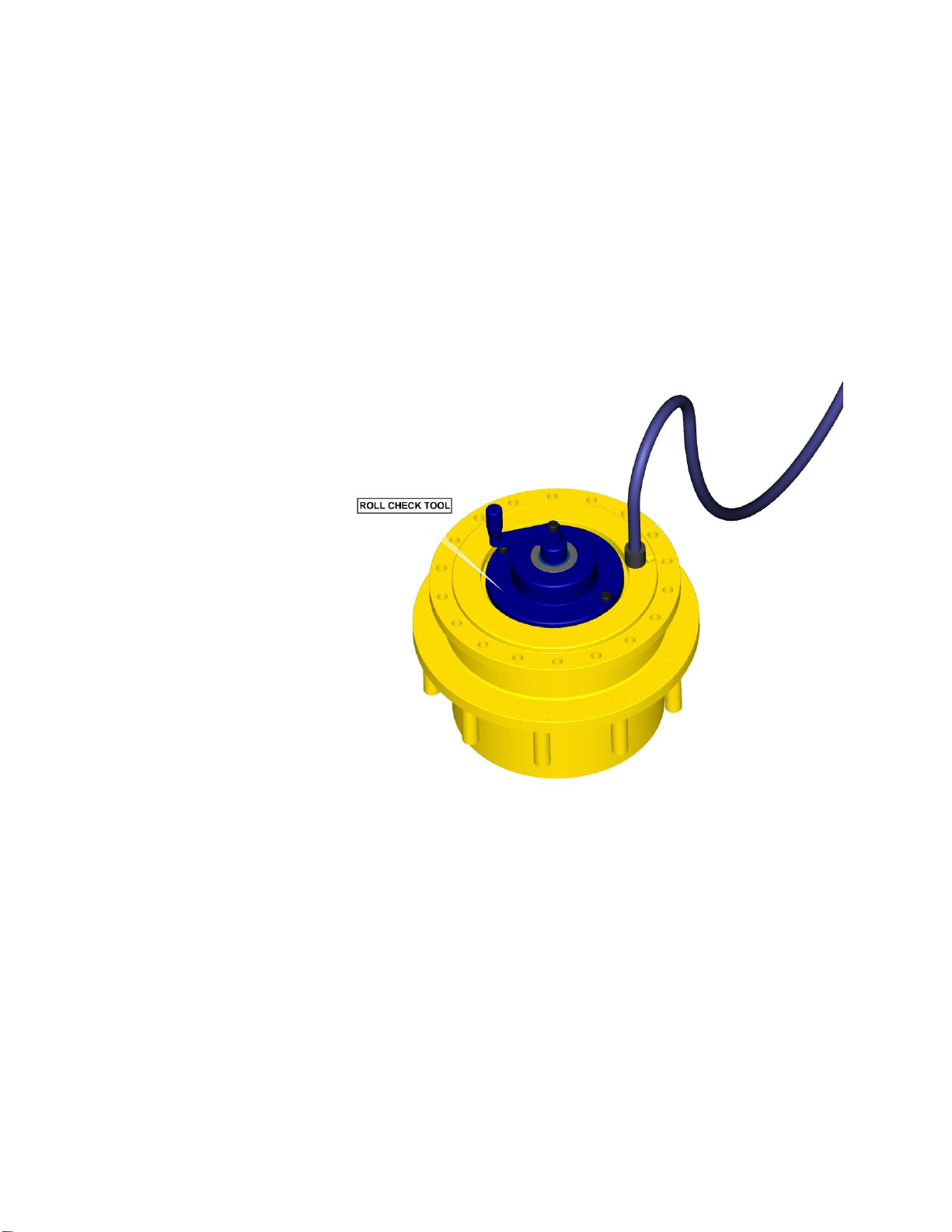
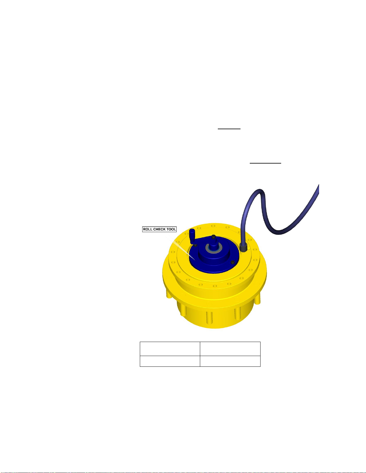
The Brake Test To perform a brake check, use a M12x1.5 metric fitting. Install a
hydraulic hand pump with pressure gauge into brake port in spindle
(1A) using metric thread fitting.
Place ROLL TEST Tool (refer to table on page 9) into input
coupling.
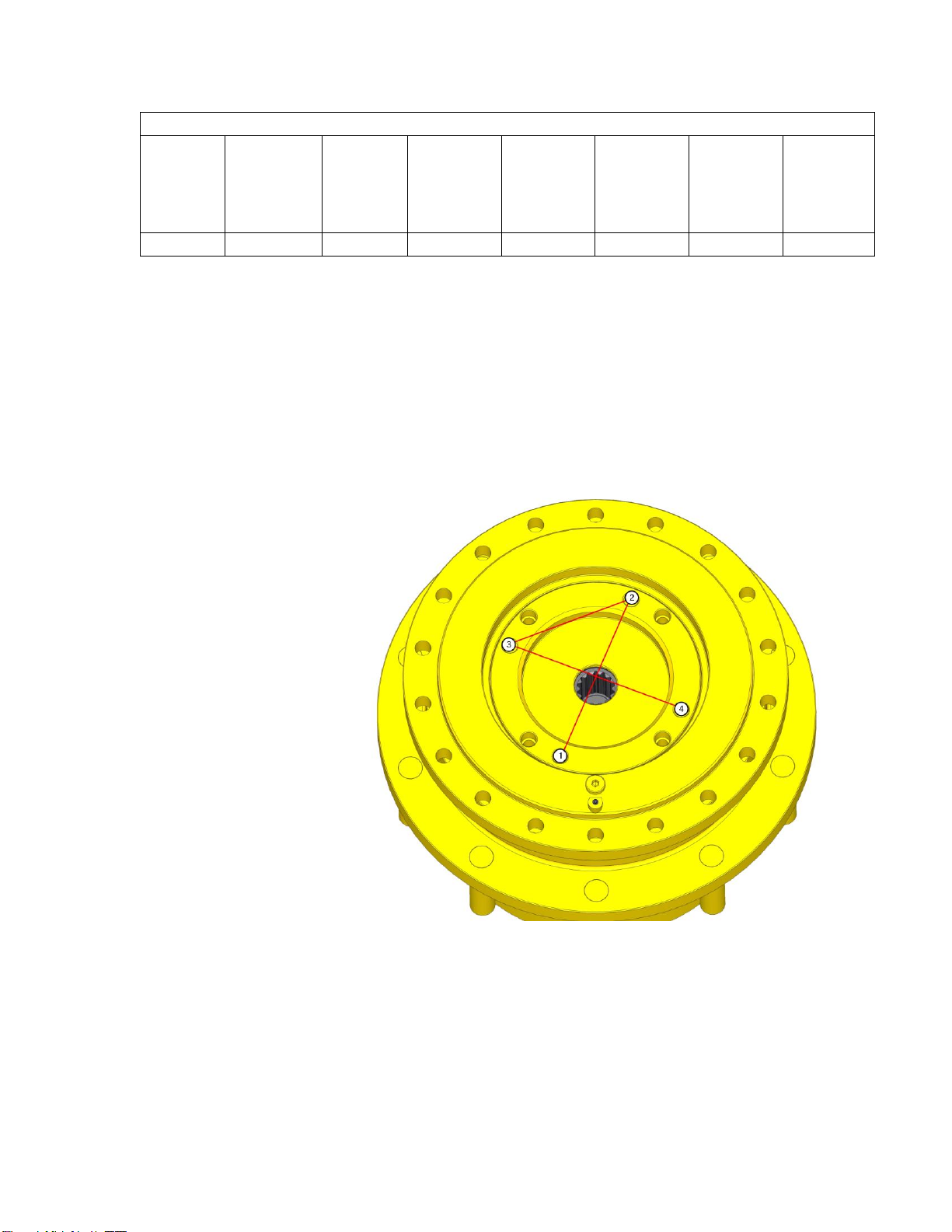
Apply 25 in-lbs torque. While trying to rotate tool, pump the handle
on the hydraulic hand pump and increase the pressure until the
brake releases. The brake is released when you are able to rotate
the tool.
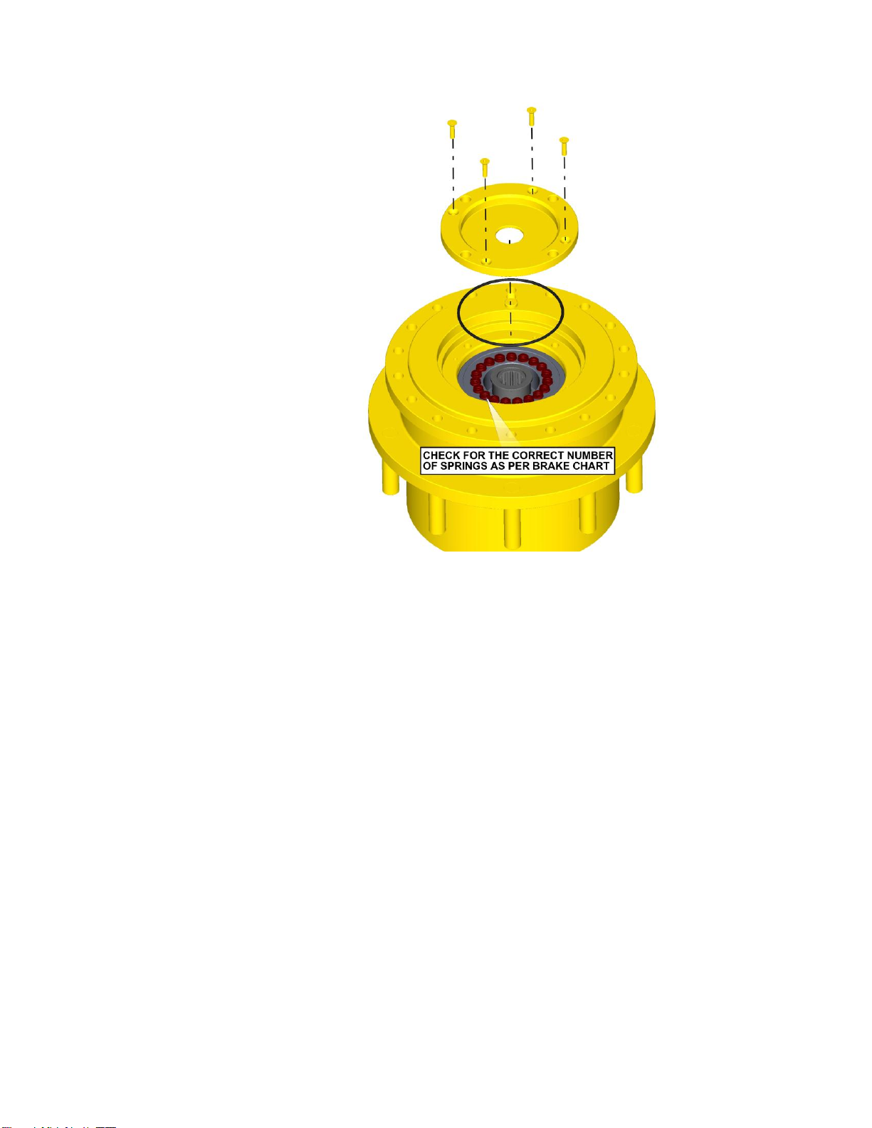
Record the release pressure. If the brake does not release within
limits shown in the brake chart on page 6, check to see if it has the
proper number of springs using the SPRING CHECKING
PROCEDURE. Increase to maximum pressure (refer to brake chart
on page 6) and hold at that pressure for one minute. If the brake
does not leak or lose pressure, the unit has passed the brake test. If
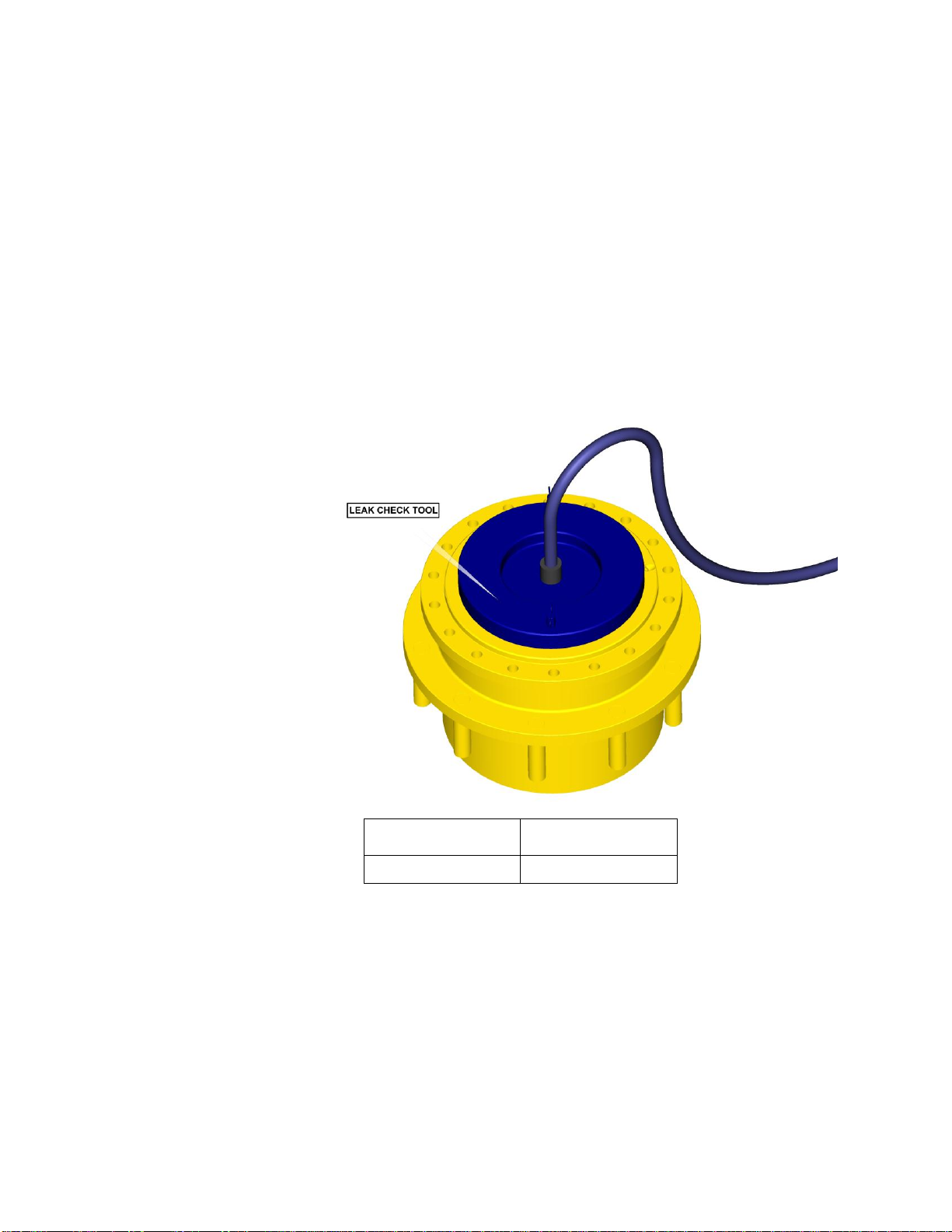
the brake loses pressure, attempt to repair the leak using the leak
repair procedure at end of this procedure.
While brake is still released, roll check the unit for one revolution of
the output member by rotating the tool. Bleed off pressure slowly
while rotating the ROLL TEST Tool.
Record the pressure at which the brake locks up. Using a clean rag,
wipe off excess fluid from around the brake port and install the pipe
plug.
Continued on Next Page

6
BRAKE CHART
8th DIGIT
IN
MODEL
CODE
(INPUT
BRAKE)
BRAKE
PART
NUMBER
NUMBER
OF
SPRINGS
RELEASE
PRESSURE
MIN (psi)
RELEASE
PRESSURE
MAX (psi)
FULL
RELEASE
PRESSURE
(psi)
MAXIMUM
PRESSURE
(psi)
BRAKE
TORQUE
(in-lbs)
D
902471
19
181
231
266
1500
5054
SPRING CHECKING PROCEDURE:
UnInstall four bolts from the Adaptor Mounting in steps using an ‘X’
pattern to ensure that brake piston remains straight while being
releasing compressed load out of brake cavity of spindle
Carefully remove the Adaptor Mounting from the end of the input
brake and count the number of springs in brake. If number of
springs matches the number in the BRAKE CHART, go to the next
step. If the number of springs does not match the number in the
BRAKE CHART above, install the correct number of springs.
Continued on Next Page

7
Install the Adaptor Mount Plate using four flat hex bolts. Install four
bolts into holes in Adaptor Mount as equally spaced as possible.
Tighten bolts in steps using an ‘X’ pattern to ensure that brake
piston remains straight while being compressed into brake cavity of
spindle.
NOTE: CARE SHOULD BE TAKEN WHILE INSTALLING OR
UNINSTALLING THE FOR FLAT HEX BOLTS ON ADAPTOR
MONT AS THEY ARE SUBJECT TO SPRING PRESSURE
Re-test the input brake. If release and/or lockup pressures still do
not match the brake chart, contact the Oerlikon Fairfield service
department.
BRAKE LEAK REPAIR PROCEDURE:
UnInstall four bolts from the Adaptor Mounting in steps using an ‘X’
pattern to ensure that brake piston remains straight while being
releasing compressed load out of brake cavity of spindle
Carefully remove the Adaptor Mounting from the end of the input
brake, remove the Brake Piston from the Spindle.
Continued on Next Page

8
Check O-rings, Backup Rings, and brake cavity in Spindle for
damage. If no damage is found, reinstall the Input Brake according
to the Input Brake Installation Procedure in the assembly
instructions chapter and perform pressure test again. If brake still
leaks, contact the Oerlikon Fairfield service department.
Reference: Sample Model C014C5_ X _ _ _ _ _ _ _ The ‘X’ is the
brake option (Model Code). Consult Oerlikon Fairfield for other
brake options.
NOTE: Failure to perform this test may result in damaged or
ineffective brake parts.

9
Planetary Final Drive Service Manual
Roll and Leak Test
Torque-Hub®units should always be roll and leak tested before
disassembly (if possible) and after assembly to make sure the unit’s
gears, bearings and seals are working properly. The following
information briefly outlines what to look for when performing these
tests.
The Roll Test The purpose of the roll test is to determine if the unit’s gears are
rotating consistently, easily and properly. It should be able to rotate
the gears in the unit applying constant force to the roll checker. If
more drag is felt in the gears only at certain points, then the gears
are not rolling consistently and easily and should be examined for
improper installation or defects. Some gear packages roll with more
difficulty than others. Do not be concerned if the gears in the unit
seem to roll hard as long as they roll with consistency. Rotate the
gearbox both clockwise and counterclockwise the same number of
turns as the ratio of the unit. The gearbox ratio is the same number
as the last three numbers on the ID tag.
Model Code
Roll Test Tool
C014C5xx4xxxxxx
T198122

10
The Leak Test The purpose of a leak test is to make sure the unit is airtight.
To perform a leak test, use the leak test fixture from the table on
page 10. If the tool is not available, the gearbox must be sealed to
perform the test. This can be accomplished by assembling the
sealed input device onto the gearbox at the input end and replace
one of the oil plugs with an air chuck. DO NOT EXCEED 10 PSI
PRESSURE DURING THE LEAK TEST. Higher pressure will create
a false sealing effect in assemblies with lip-seals. The unit has a
leak if the pressure gauge reading on your leak check fitting starts
to fall after the gearbox has been pressurized and allowed to
equalize. Leaks will most likely occur at the pipe plugs, the main
seal or wherever o-rings or gaskets are located. The exact location
of a leak can usually be detected by brushing a soap and water
solution around the main seal and where the o-rings or gaskets
meet on the exterior of the unit and then checking for air bubbles. If
a leak is detected in a seal, o-ring or gasket, the part must be
replaced and the unit rechecked. Leak test at 10 psi for 20 minutes.
Model Code
Leak Test Tool
C014C5xx4xxxxxx
T205708

11
Planetary Final Drive Service Manual
Tightening and Torquing Bolts
If an air impact wrench is used to tighten bolts, extreme care should
be taken to ensure the bolts are not tightened beyond their specified
torque. The following steps describe how to tighten and torque bolts
or socket head cap screws in a bolt circle.
1. Tighten (but do not torque) bolt “A” until snug.
2. Go to the opposite side of the bolt circle and tighten bolt “B” until
equally snug.
3. Crisscross around the bolt circle and tighten the remaining bolts.
4. Use a torque wrench to apply the specified torque to bolt “A.”
5. Using the same sequence, crisscross around the bolt circle and
apply an equal torque to the remaining bolts.

12
Planetary Final Drive Service Manual
Lubrication Information
General Properties The lubricant used in most Torque-Hub®drives should be
petroleum-based gear fluid containing anti-oxidation, anti-foaming
and extreme pressure additives. The lubricant should have a
minimum viscosity index of 95 cst and maintain a minimum viscosity
of 40 cst under normal operating conditions. Some applications
require special considerations; consult the machine manufacturer
and Oerlikon Fairfield for more additional information.
The table below lists the recommended viscosities for various
ambient operating temperatures. These recommendations are
based on temperature rise of 50° to 100°F at normal operating
conditions.
Continued on Next Page
Differential Planetary Simple Planetary
Ambient
Temperature
ISO Index
AGMA
Lubricant
Number
ISO Index
AGMA
Lubricant
Number
-40° to -5° F(1)
VG100
3EP
VG100
3EP
-5°to 40° F
VG150
4EP
VG100
3EP
40° to105° F
VG220/VG320
5EP/6EP
VG150/VG220
4EP/5EP
105° to 150° F(2)
VG460
7EP
VG320
6EP
Footnotes
1. For operation in this ambient temperature range, synthetic oil is recommended with a pour point of
10°F lower than the minimum ambient temperature.
2. For operation in this ambient temperature range, synthetic oil is recommended for proper lubricant
life at elevated temperatures.

13
Maintenance Oil amounts for each series of Torque-Hub®drives are indicated in
the appropriate series literature. An initial oil change should be
made after the first 50 hours of operation. Subsequent oil changes
should be made at 1,000 hour intervals or annually, whichever
comes first.
Oil temperatures should be not higher than 160° to 180°F for
continuous operation, and no higher than 200°F for intermittent
operation. For special applications, high horsepower, high speeds
or wide temperature changes, please consult Oerlikon Fairfield.
Oil Fill Level When the Torque-Hub®unit is mounted horizontally, unless
otherwise specified, the gearbox should be filled half-full of oil.
Consult the appropriate series literature for approximate fill
volumes. Vertically mounted Torque-Hub®units may require special
lubrication procedures. Please contact Oerlikon Fairfield for
vertically mounted applications.

14
THIS PAGE
INTENTIONALLY
LEFT BLANK

15
DISASSEMBLY

16
Planetary Final Drive Service Manual
Main Disassembly
1. Perform a roll check and a leak check prior to disassembling the unit.
2. Remove the two magnetic Pipe Plugs (16 & 25) and drain the oil out of the gearbox.
NOTE: Record the condition and volume of the oil.
3. Remove the Retaining Ring (4) from the Housing.
4. Lift the Cover Subassembly off of the unit.
Continued on Next Page

17
5. Remove the Input Sun Gear (6) if applicable.
6. Remove the Input Shaft (9) from Hub-Spindle Subassembly.
7. Lift out the Input Carrier Subassembly from Hub-Spindle Subassembly.
CAUTION: Safety glasses must be worn during these next steps.
8. UnInstall four bolts (14) from the Adaptor Mounting (12) in steps using an ‘X’ pattern to
ensure that brake piston remains straight while being releasing compressed load out of
brake cavity of spindle
9. Remove the Adaptor Mounting (12) from Hub-Spindle Subassembly
10. Remove the O-ring (10B) from Adaptor Mounting (12).
11. Remove the Input Coupling Subassembly from the Hub-Spindle Subassembly.
12. Remove the Input Brake Subassembly out of Hub-Spindle Subassembly (Refer page 21 for
detailed Input Brake Disassembly).
This concludes the Main Disassembly.

18
THIS PAGE
INTENTIONALLY
LEFT BLANK

19
Planetary Final Drive Service Manual
Cover Disassembly
1. Remove the O-Ring (5) from groove in the Cover (2) and discard O-Ring.
2. Remove Thrust Washers (3) from pocket in the Cover (2).
This concludes the Cover Disassembly.

20
Planetary Final Drive Service Manual
Input Carrier Disassembly
1. Drive the Planet Shaft (8D) out of the carrier pin holes; forcing the Roll Pin (8E) to sheer off.
2. Hold on to the Planet Gear (8F) and push the Planet Shaft (8D) out of the Carrier (8A). The
Thrust Washers (8B) will slide off the shaft as it is removed.
3. Using a hammer and punch, drive the Roll Pin (8E) out of the Planet Shaft (8D) and Carrier
(8A).
4. Remove the Needle Bearings (8C) from the inside of the Planet Gear (8F).
5. Repeat steps 1-4 for the remaining two Planet Gears (8F).
CAUTION: Safety glasses must be worn during these next steps.
6. Carefully remove the Retaining Ring (15) from groove in the Output Sun Gear (7).
7. Remove the Output Sun Gear (7) out of Carrier (8E).
This concludes the Input Carrier Disassembly.
Table of contents
Other Oerlikon Fairfield DC Drive manuals
Popular DC Drive manuals by other brands

Festo
Festo DFPI ND2P-E-NB3 Series operating instructions

Pfeiffer Vacuum
Pfeiffer Vacuum TCP 350 PN operating instructions

sauter
sauter AXM 117 F202 Fitting instructions

YASKAWA
YASKAWA CANopen SI-S3 installation manual

Rexnord
Rexnord Falk CT Series Operation and maintenance

Siemens
Siemens 6SL3766-1CA00-0AA0 Supplementary sheet / description