Ofcine Gullo8
DECLARATION OF COMPLIANCE
This appliance is manufactured by OFFICINE GULLO S.r.l
Headquarters and factory
Via Della Torricella 29, Antella, Bagno a Ripoli
50012 Florence - Italy
Tel. +39 055 65 60 3324
+39 055 62 18 07
ofcinegullo.com | info@ofcinegullo.com
The manufacturer declares that the appliances are compliant with the prescriptions of the EEC norm 2009/142
for the gas part and with norm 2006/95/CE, 2004/108/CE for the electric part. The installation must be done
observing the norms in force particularly concerning room ventilation and discharging gas emissions.
N.B.: The manufacturer declines any responsibility for direct or indirect damage caused by improper or incorrect
installation, alterations, maintenance or use of the appliance, as in all the other cases considered in the items of our
sales conditions.
GAS TECHNICAL DATA TABLE
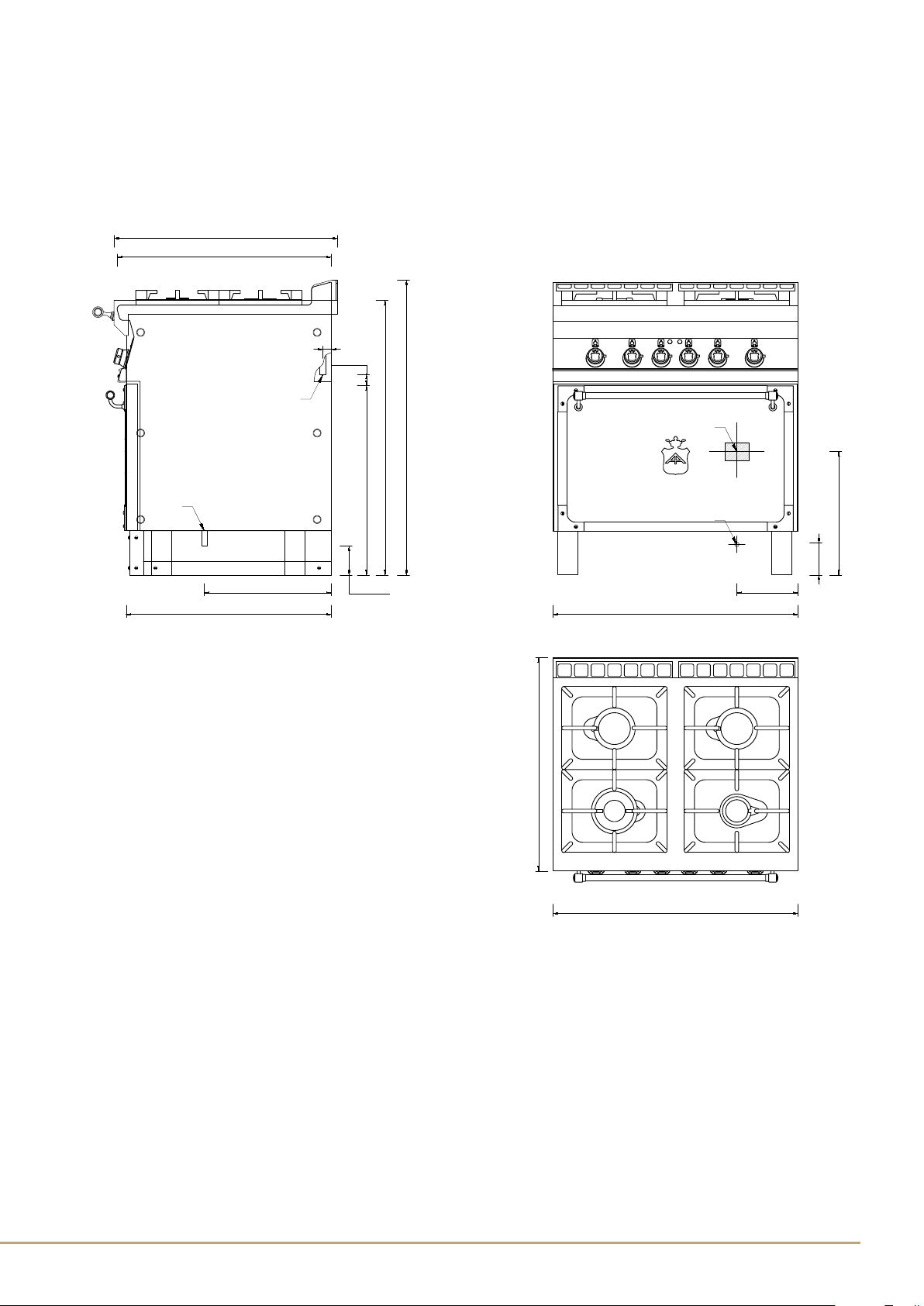
MODEL Dimensions
cm
NOMINAL BURNER CAPACITY
kW
TOT. NOM.
CAPACITY
kW Gas coupling
ISO 7-1
Burner
3,5 kW
Burner
5,5 kW
Burner
7,5 kW Gas
GEFS8P 80x70x90h 1 2 1 22 R3/4GM
ELECTRIC TECHNICAL DATA TABLE
MODEL Dimensions
cm Power Supply
Tot.
power
(KW)
Max.
absorb
A
Power
supply
cable mm²
GEFS8P 80x70x90h 400V~3N 50/60 Hz 5,32 8,06 5x1,5
GEFS8P 80x70x90h 230V 50/60 Hz 5,32 13,35 4x1,5
9
Ofcine Gullo
INSTALLATION
• The operations for installing, conversions for use with other types of gas and starting up must be done only
by qualied personnel whose qualications comply with the norms in force.
• Gas installations, the electrical connections and the rooms in which the appliances are installed must comply
with the norms in force in the Country in which the installation is carried out; above all, the appliance must
be installed in a well ventilated room, preferably under an extractor hood, so as to ensure the complete
extraction of gas emissions which are formed during combustion. The air necessary for combustion is
2m3/h per kW of power installed.
Attention: In accordance with international rules, when connecting the appliance, an automatic device enabling the
disconnection of all contacts from the mains, must be installed above it; this device must have a contacts opening
of at least 3 mm.
CHECKING FOR ADEQUATE VENTILATION
Make sure that the air intake into the room where the appliance is installed is sufcient for an adequate change of air, as
specied by regulations in effect.
The appliances installed in buildings open to the public must satisfy the following requirements.
Installation rules
The installation and maintenance of the appliance must be done according to the correct procedures and regulation
texts in use, particularly:
• safety standards for the prevention of re and panic.
Connection and installation of appliance, ventilation and exhaust removal systems, shall be done according to the
Manufacturer’s instructions and by qualied technicians and according to the regulations in effect. The electric wiring shall
conform to the regulations in effect.
All re prevention codes shall be observed.
a) General indications (Rules valid for GB only)
- For all appliances:
Gas safety Regulations, 1984; Health and safety at Work Act, 1974 Codes of Practice, BS 8173, 1982, The Building
Regulations 1985; The Building Standards Regulations, 1981, the IEE Regulations and the by-laws of the local Water
Undertaking.
The local gas Region or LPG supplier and the local authority and the relevant recommendation of the British Standards
(latest editions) concerned.
The installation, transformation and repair of appliances for professional kitchens as well as removal due to malfunction,
and the supply of gas, may be made only by means of a maintenance contract stipulated with an authorized sales ofce
and in observance of technical regulations.
The appliance can be installed by itself or in a series side by side with appliances produced by us.
There must be a minimum distance of at least 10 cm between the appliance and the sides of the nearby cabinets made
of inammable material.
Take suitable measures to guarantee thermal insulation of the inammable sides, such as, for example, the installation of
protection against radiation.
The appliances must be installed in a suitable manner, observing the safety standards.
The small feet are adjustable to level the appliance.