OfiTE 120-60 User manual

Model 20 Constant Speed Blender
120-60: For Cement, 115 Volt
120-60-1: For Cement, 230 Volt
120-60-F: For Fracturing Fluids, 115 Volt
120-60-1-F: For Fracturing Fluids, 230 Volt
Instruction Manual
Updated 11/16/2015
Ver. 5.0
OFI Testing Equipment, Inc.
11302 Steeplecrest Dr. · Houston, Texas · 77065 · U.S.A.
Tele: 832.320.7300 · Fax: 713.880.9886 · www.ote.com
©Copyright OFITE 2015

OFITE, 11302 Steeplecrest Dr., Houston, TX 77065 USA / Tel: 832-320-7300 / Fax: 713-880-9886 / www.ote.com 1
Intro..................................................................................................2
Description......................................................................................2
Specications .................................................................................3
Components ...................................................................................3
Installation.......................................................................................7
Operation.........................................................................................8
Manual Mode ..............................................................................8
Variable Mode .............................................................................9
Auto Mode...................................................................................9
Timer .........................................................................................10
Speed Controller .......................................................................10
PID Parameters ........................................................................ 11
Warranty and Return Policy ........................................................12
Table of
Contents

OFITE, 11302 Steeplecrest Dr., Houston, TX 77065 USA / Tel: 832-320-7300 / Fax: 713-880-9886 / www.ote.com 2
OFITE’s Model 20 Constant Speed Blender was designed to prepare well
cements for testing according to the guidelines stated within API Specication
10. Research has demonstrated that the properties of well cements are
highly dependent upon mixing procedures. In addition, studies have indicated
that when constant speed blenders/mixers are used, data obtained from
thickening time tests has greater reproducibility and generally correlates
better with data obtained from other laboratories. The Model 20 was designed
to provide a means of consistently preparing cement slurries for testing
purposes and can be utilized to mix cements according to the procedures
stated by the API.
The proper amount of mix water is carefully weighed and poured into the
mixing container of the blender. The rotational speed is set to 4,000 RPM
and allowed to stabilize at this speed. The “TIMER” switch is pressed and
the cement is immediately added to the mix water. The cement should be
uniformly added to the water in less than 15 seconds. After 15 seconds the
rotational speed is automatically increased to 12,000 RPM and the slurry is
mixed an additional 35 seconds. A microprocessor is utilized to maintain the
rotational speed within the recommendations established by the API and is
independent of uctuations in line voltage and the viscosity of the cement
slurry.
The 120-60-F Constant Speed Blender is intended for testing Fracturing
Fluids. The rotational speeds are set to 500 and 1,000 RPM respectively.
Intro
Description

OFITE, 11302 Steeplecrest Dr., Houston, TX 77065 USA / Tel: 832-320-7300 / Fax: 713-880-9886 / www.ote.com 3
Components #122-074 Fuse, 4 Amp, 5 mm × 20 mm (230 Volt Only)
#122-074-1 Fuse, 5 Amp, 5 mm × 20 mm (230 Volt Only)
#122-075 Fuse, 7 Amp, 5 mm × 20 mm (115 Volt Only)
#122-077 Fuse, 10 Amp, 5 mm × 20 mm (115 Volt Only)
#122-200 Hardened Blade Assemblies
#122-202 Container, Stainless Steel
#122-203 Container Lid
#122-204 Bottom Gasket
#122-209 Waring Blender®230 V with Exciter Gear and Pickup Cable
#122-210 Waring Blender®115 V with Exciter Gear and Pickup Cable
#152-34 Container, Glass (For Fracturing Fluids)
#164-42 Male Connector for Power Cable (230 Volt Only)
Optional:
#120-61 Spare Parts Kit, 115 Volt
#122-075 Fuse, 7 Amp, 5 mm × 20 mm (115 Volt Only), Qty: 4
#122-077 Fuse, 10 Amp, 5 mm × 20 mm (115 Volt Only), Qty: 4
#122-200 Blending Assembly / Square Drive, 1 qt., Qty: 12
#122-202 Stainless Steel Container, 1 qt.
#122-203 Container Lid, 1 qt.
#122-204 Bottom Gasket, Qty: 6
#120-61-1 Spare Parts Kit, 230 Volt
#122-074 Fuse, 4 Amp, 5 mm × 20 mm, Qty: 4
#122-074-1 Fuse, 5 Amp, 5 mm × 20 mm, Qty: 4
#122-200 Blending Assembly / Square Drive, 1 qt., Qty: 12
#122-202 Stainless Steel Container, 1 qt.
#122-203 Container Lid, 1 qt.
#122-204 Bottom Gasket, Qty: 6
- Hardened stainless steel mixing blades
- Stainless steel 1-liter mixing container
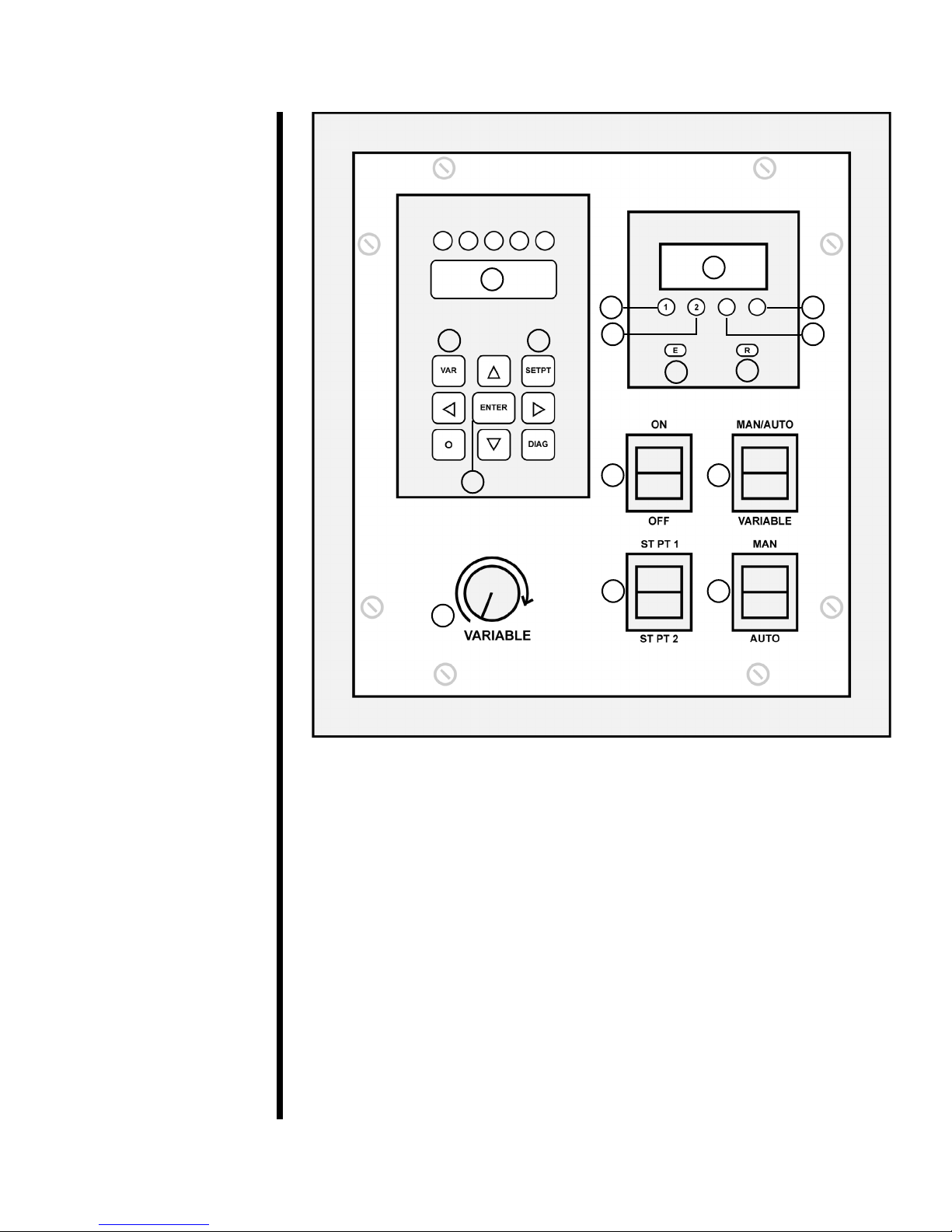
- Two preset mixing speeds and variable speed
- Maximum Speed for Cement Testing (120-60 / 120-60-1): 16,000 RPM
- Maximum Speed for Fracturing Fluid Testing (120-60-F / 120-60-1-F):
5,000 RPM
- Rotational speed is maintained at setpoint with microprocessor
- Timing relays automatically control mixing times at required RPM
- Digital instrumentation provides excellent readability
- Crated Size: 45" × 32" × 12" (114 × 81 × 31 cm)
- Crated Weight: Approximately 75 pounds (34.1 kg)
Specications

OFITE, 11302 Steeplecrest Dr., Houston, TX 77065 USA / Tel: 832-320-7300 / Fax: 713-880-9886 / www.ote.com 4
1
2
3
4 6
5
78
9 10
11 12 13
14 15
16
1. Rotational Speed Display (RPM)
This display shows the speed of the blade. On models for cement
testing (120-60 / 120-60-1), multiply the value displayed here by 10
to determine the actual RPM of the blade.
2. Timer Display (Seconds)
3. Edit Setpoint 1 / Increase Setpoint Digit
Press this button to change the timer value of Setpoint 1. When
editing a setpoint value, this button increases the rst digit of the
value by 1.

OFITE, 11302 Steeplecrest Dr., Houston, TX 77065 USA / Tel: 832-320-7300 / Fax: 713-880-9886 / www.ote.com 5
4. Edit Setpoint 2 / Increase Setpoint Digit
Press this button to change the timer value of Setpoint 2. When
editing a setpoint value, this button increases the second digit of
the value by 1.
5. Increase Setpoint Digit
This button increases the fourth digit of the setpoint value by 1.
6. Increase Setpoint Digit
This button increases the third digit of the setpoint value by 1.
7. Enter Button
Press this button to store the Setpoint value in memory.
8. Timer Reset
Press this button to reset the timer to zero.
9. Keypad: VAR
This button accesses the PID Parameter Control Menu.
10.Keypad: SETPT
Press this button to change the rotational speed of Setpoint 1 or
Setpoint 2.
11. Keypad: ENTER
Press this button to store the Setpoint value in memory.
12.Two-Way Switch: ON - OFF
This switch provides power to the unit.
13.Two-Way Switch: MAN/AUTO - Variable
This switch determines the operating mode of the unit. If it is set to
MAN/AUTO, the MAN - AUTO switch (15) becomes active. If it is
set to VARIABLE, the unit will be in Variable Mode.

OFITE, 11302 Steeplecrest Dr., Houston, TX 77065 USA / Tel: 832-320-7300 / Fax: 713-880-9886 / www.ote.com 6
14.Three-Way Switch: ST PT 1 / ST PT 2
This switch remains inactive unless the MAN/AUTO - Variable
switch (13) is set to MAN/AUTO and the MAN - AUTO switch (15)
is set to MAN. It toggles the rotational speed between Setpoint 1
and Setpoint 2. If it is in the center position, the unit will not rotate.
For testing Cement (part numbers 120-60 and 120-60-1), Setpoint 1
is 4,000 RPM and Setpoint 2 is 12,000 RPM. For testing Fracturing
Fluids, Setpoint 1 is 500 and Setpoint 2 is 1,000 RPM.
15.Three-Way Switch: MAN - AUTO
This switch remains inactive unless the MAN/AUTO - Variable
switch (13) is set to MAN/AUTO. It toggles the operating mode
between Manual Mode and Auto Mode. If it is in the center position,
the unit will not rotate.
16.Potentiometer
This knob remains inactive unless the MAN/AUTO - Variable
switch (13) is set to Variable. It provides greater control over the
rotational speed of the unit.

OFITE, 11302 Steeplecrest Dr., Houston, TX 77065 USA / Tel: 832-320-7300 / Fax: 713-880-9886 / www.ote.com 7
Installation 1. Carefully remove the unit from the packing box and place it on a counter
safely away from sinks and other possible hazards.
2. Place the blending assembly on the base of the unit.
3. Plug the power supply cord into the port underneath the cabinet housing
labeled “BLENDER”.
4. Plug the transducer cable into the center port and fasten in place with the
two clamps and screws provided. Do not over tighten.
5. Finally, plug the power supply cord into a suitable AC power supply.

OFITE, 11302 Steeplecrest Dr., Houston, TX 77065 USA / Tel: 832-320-7300 / Fax: 713-880-9886 / www.ote.com 8
Operation The blending assembly has two speeds, “HI” and “LO”. The Constant Speed
Blender will not operate unless the blending assembly is set to “HI”. Before
operation, press the “HI” button on the blending assembly.
The unit has three operating modes: Manual, Variable, and Auto. The MAN/
AUTO - Variable switch (13) and the MAN/AUTO switch (15) set the mode.
1. To set the unit to Manual Mode, set the MAN/AUTO - Variable switch (13)
to MAN/AUTO and the MAN - AUTO switch (15) to MAN.
2. To set the unit to Auto Mode, set the MAN/AUTO - Variable switch (13) to
MAN/AUTO and the MAN - AUTO switch (15) to AUTO.
3. To set the unit to Variable Mode, set the MAN/AUTO - Variable switch
(13) to Variable.
Before turning the unit on, be sure to set the MAN/AUTO switch (15)
and the ST PT 1 / ST PT 2 switch (14) to the center position and turn
the Potentiometer (16) fully counter-clockwise.
1. Place the mix water into the mixing cup and place the lid on top of the
container.
2. The MAN/AUTO - Variable switch (13) should be in the MAN/AUTO
position. The MAN/AUTO switch (15) should be in the MAN position.
3. Place the ST PT 1 / ST PT 2 switch (14) to the ST PT 1 position to start
the unit.
When you initially start the unit, the rotational speed may exceed the
setpoint, but will stabilize within a few seconds.
4. After stabilization, you have 15 seconds to add the cement to the mix
water and cover the container with the lid. Reset the timer to zero by
pressing the Reset Button (8).
5. After 15 seconds, increase the rotational speed by setting the ST PT 1 /
ST PT 2 switch (14) to ST PT 2.
6. After mixing the cement an additional 35 seconds, stop the blender by
setting the ST PT 1 / ST PT 2 switch (14) to the center position.
7. Return the MAN/AUTO switch (15) to the center position.
8. After mixing is complete, clean the blending cup and lid as soon as
possible to prevent any cement from building up on the container.
Operation
Manual Mode

OFITE, 11302 Steeplecrest Dr., Houston, TX 77065 USA / Tel: 832-320-7300 / Fax: 713-880-9886 / www.ote.com 9
Operation
Variable Mode
1. Place the mix water into the mixing cup and place the lid on top of the
container. Ensure that the potentiometer control knob is in the fully
counter-clockwise position.
2. Make certain that the ST PT 1 / ST PT 2 switch (14) is in the center
position. Place the MAN/AUTO - VARIABLE (13) switch in the Variable
position.
3. Increase the rotational speed of the blender by turning the control
Potentiometer (16) clockwise.
4. Reset the timer to zero by pressing the reset button (8).
5. After mixing is complete, clean the blending cup and lid as soon as
possible to prevent any cement from building up on the container.
1. Place the mix water into the mixing cup and place the lid on top of the
container.
2. Make certain that the ST PT 1 / ST PT 2 switch (14) is in the center
position. Place the MAN/AUTO - VARIABLE switch (13) to the MAN/
AUTO position. Place the MANUAL/AUTO switch (15) switch to the
AUTO position.
Once the switch is placed into the AUTO position, the blender
should start to accelerate. If the blender does not accelerate, reset
the timer by pressing the reset button (8).
When you initially start the unit, the rotational speed may exceed the
setpoint, but will stabilize within a few seconds.
3. After stabilization, reset the timer to zero again and immediately begin
adding the cement. You have 15 seconds to add the cement to the mix
water and place the lid on the container.
After 15 seconds the timer will automatically increase the rotational
speed to Setpoint 2. Ensure that the cement is added to the mix
water and that the lid is placed on the container in less than 15
seconds.
4. After mixing the cement at Setpoint 2 for 35 seconds the timer will
automatically stop the blender.
5. After mixing is complete, clean the blending cup and lid as soon as
possible to prevent any cement from building up on the container.
Operation
Auto Mode

OFITE, 11302 Steeplecrest Dr., Houston, TX 77065 USA / Tel: 832-320-7300 / Fax: 713-880-9886 / www.ote.com 10
Operation
Timer
The timer is continuously on whenever power is applied to the unit. The unit
will measure elapsed time to its maximum value and then stop at setpoint 2.
By default, setpoint 1 is set to 15 seconds and setpoint 2 is set to 50 seconds.
These values conform to the guidelines established in API Specication 10.
To change these values, do the following:
1. Press “1” (3) or “2” (4) to change setpoint 1 or setpoint 2 respectively.
2. The display will show the current setpoint value. The four buttons beneath
the display (3 – 6) each increase a separate digit of the setpoint value.
The digits will scroll from 0 to 9 and then return to 0.
3. When you reach the correct setpoint value, press the enter button (7) to
store it in the timer's memory.
The Constant Speed Blender has two setpoints that are set at the factory.
For Cementing testing, Setpoint 1 and Setpoint 2 are set to 4,000 and 12,000
RPM respectively. For Fracturing Fluid testing, they are set to 500 and 1,000
RPM.
To change these values, do the following:
1. Press “SETPT” (10) to activate the speed control menu.
2. Use the arrow keys to scroll to either “SETPOINT 1” or “SETPOINT 2”.
3. Press “ENTER” (11).
4. Key in the numeric value (rotational Speed) of the new setpoint with the
keypad.
5. Press “ENTER” (11) to store the new value into the controller’s memory.
Operation
Speed Controller

OFITE, 11302 Steeplecrest Dr., Houston, TX 77065 USA / Tel: 832-320-7300 / Fax: 713-880-9886 / www.ote.com 11
For optimum performance, it may be necessary to change the PID
parameters within the controller. To tune the controller, do the following:
1. Operate the unit in Manual Mode with a typical uid within the container.
Toggle between ST PT 1 and ST PT 2 and watch for over or undershoot.
If there is signicant overshoot access “VARIABLE 9” and reduce the
value by 4.
To access “VARIABLE 9” press the “VAR” (9) key, press “9”, and then
press “ENTER” (11). Key in the new value and press “ENTER” (11) to
store it into memory.
If there is no overshoot or undershoot, but the response was slow,
increase the value of “Variable 9” by 4.
Repeat the above procedure, changing the value of “VARIABLE 9” until
there is minimal overshoot and the ramp is smooth. Note that to ne tune
the controller, the value can be incremented in steps of 1 or 2 and not
necessarily a value of 4.
Variable 10 may be accessed and changed in the same manner.
2. Run the controller at ST PT 2. Increase “VARIABLE 10” by 4 and watch
for any oscillations around the setpoint. If no oscillations occur increase
“Variable 10” by 4 until oscillations begin.
3. After the onset of oscillations, reduce “VARIABLE 10” by 4.
4. Repeat steps 2 and 3 until minimal over and undershoot occur.
This is a trial and error process. After each change, record the setting and its
result. Variable 9 and 10 are initially set to 10 and 8 respectively.
Operation
PID Parameters

OFITE, 11302 Steeplecrest Dr., Houston, TX 77065 USA / Tel: 832-320-7300 / Fax: 713-880-9886 / www.ote.com 12
Warranty and
Return Policy
Warranty:
OFI Testing Equipment, Inc. (OFITE) warrants that the products shall be free from liens and defects in
title, and shall conform in all respects to the terms of the sales order and the specications applicable
to the products. All products shall be furnished subject to OFITE’s standard manufacturing variations
and practices. Unless the warranty period is otherwise extended in writing, the following warranty shall
apply: if, at any time prior to twelve (12) months from the date of invoice, the products, or any part
thereof, do not conform to these warranties or to the specications applicable thereto, and OFITE is
so notied in writing upon discovery, OFITE shall promptly repair or replace the defective products.
Notwithstanding the foregoing, OFITE’s warranty obligations shall not extend to any use by the buyer
of the products in conditions more severe than OFITE’s recommendations, nor to any defects which
were visually observable by the buyer but which are not promptly brought to OFITE’s attention.
In the event that the buyer has purchased installation and commissioning services on
applicable products, the above warranty shall extend for an additional period of twelve
(12) months from the date of the original warranty expiration for such products.
In the event that OFITE is requested to provide customized research and development for the buyer,
OFITE shall use its best efforts but makes no guarantees to the buyer that any products will be provided.
OFITE makes no other warranties or guarantees to the buyer, either express or implied,
and the warranties provided in this clause shall be exclusive of any other warranties
including ANY IMPLIED OR STATUTORY WARRANTIES OF FITNESS FOR PURPOSE,
MERCHANTABILITY, AND OTHER STATUTORY REMEDIES WHICH ARE WAIVED.
This limited warranty does not cover any losses or damages that occur as a result of:
• Improper installation or maintenance of the products
• Misuse
• Neglect
• Adjustment by non-authorized sources
• Improper environment
• Excessive or inadequate heating or air conditioning or electrical
power failures, surges, or other irregularities
• Equipment, products, or material not manufactured by OFITE
• Firmware or hardware that have been modied or altered by a third party
• Consumable parts (bearings, accessories, etc.)
Returns and Repairs:
Items being returned must be carefully packaged to prevent damage in
shipment and insured against pos
sible damage or loss. OFITE will not be
responsible for equipment damaged due to insufcient packaging.
Any non-defective items returned to OFITE within ninety (90) days of invoice are subject to a
15% restocking fee. Items returned must be received by OFITE in original condition for it to
be accepted. Reagents and special order items will not be accepted for return or refund.
OFITE employs experienced personnel to service and repair equipment manufactured by us, as
well as other companies. To help expedite the repair process, please include a repair form with all
equipment sent to OFITE for repair. Be sure to include your name, company name, phone number,
email address, detailed description of work to be done, purchase order number, and a shipping address
for returning the equipment. All repairs performed as “repair as needed” are subject to the ninety (90)
day limited warranty. All “Certied Repairs” are subject to the twelve (12) month limited warranty.
Returns and potential warranty repairs require a Return Material Authorization (RMA)
number. An RMA form is available from your sales or service representative.
Please ship all equipment (with the RMA number for returns or warranty repairs) to the following address:
OFI Testing Equipment, Inc.
Attn: Repair Department
11302 Steeplecrest Dr.
Houston, TX 77065
USA
OFITE also offers competitive service contracts for repairing and/or maintaining your lab
equipment, in
cluding equipment from other manufacturers. For more information about
our technical support and repair services, please contact techservice@ote.com.
This manual suits for next models
3
Table of contents