OfiTE 120-75 User manual

Atmospheric Consistometer
#120-75 (115V)
#120-75-1 (220V)
Instruction Manual
Updated 3/6/2023
Ver. 8
OFI Testing Equipment, Inc.
11302 Steeplecrest Dr. · Houston, Texas · 77065 · U.S.A.
Tele: 832.320.7300 · Fax: 713.880.9886 · www.ote.com
©Copyright OFITE 2015

OFITE, 11302 Steeplecrest Dr., Houston, TX 77065 USA / Tel: 832-320-7300 / Fax: 713-880-9886 / www.ote.com 1
Intro..................................................................................................2
Description......................................................................................2
Features...........................................................................................2
Requirements .................................................................................2
Components ...................................................................................3
Setup................................................................................................5
Loading the Test Cells ...................................................................6
On-Screen Display .........................................................................7
Operation.........................................................................................8
Calibration.......................................................................................9
Torque Head ...............................................................................9
Temperature..............................................................................10
Motor Speed .............................................................................10
Timer.........................................................................................10
Test Setup ..................................................................................... 11
Maintenance..................................................................................13
Warranty and Return Policy ........................................................15
Table of
Contents

OFITE, 11302 Steeplecrest Dr., Houston, TX 77065 USA / Tel: 832-320-7300 / Fax: 713-880-9886 / www.ote.com 2
The Model 60 Atmospheric Consistometer is designed to condition cement
slurries as specied within API Specication 10. Determination of rheological
properties and examination of free water content require that the cement
slurry be conditioned prior to testing. The OFITE Model 60 was specically
developed to perform these duties.
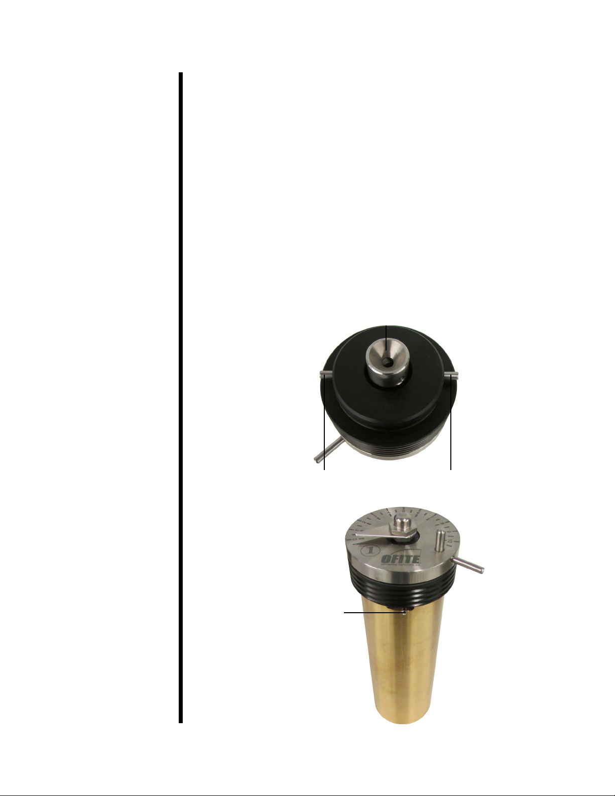
A cement slurry is prepared according to the procedure outlined in the
API Specication 10 and then placed in the slurry containers of the
Model 60 Atmospheric Consistometer. The slurry is stirred at 150 RPM
by an API-designed paddle assembly. The temperature is controlled by
a microprocessor, which displays the process temperature via a digital
indicator. Consistency, measured in Bearden Units of Consistency, is
determined by measuring the deection of a calibrated spring. The spring is
connected to a pointer that rotates on a scale (numbered 1 through 10) on
the slurry container lid. This deection is created by the amount of torque that
the cement slurry exerts on the paddle, which is a function of the consistency
of the cement. The API denes 100 Bc as 2,080 g-cm of torque and each
number on the lid is a multiple of 10 (1 equals 10 Bc, 5 equals 50 Bc, and 10
equals 100 Bc).
- Redesigned frame and bearings reduces noise during operation
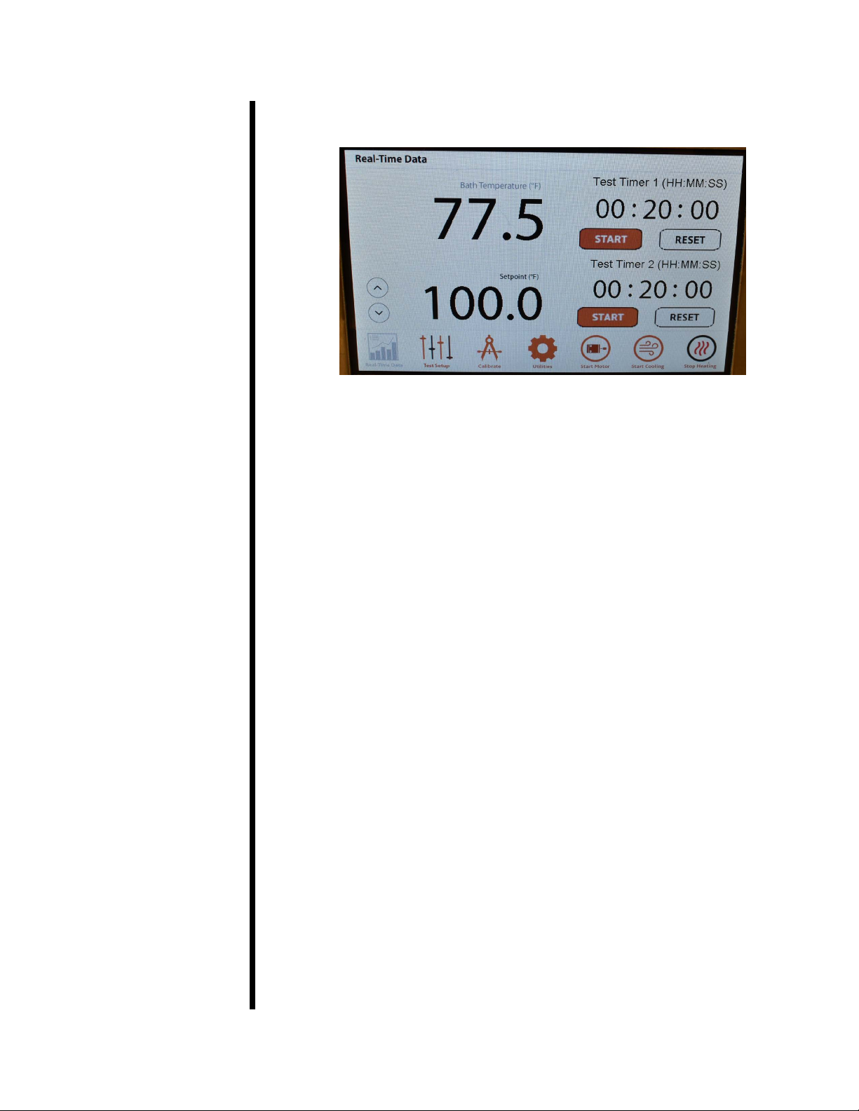
- Dual countdown timers that provide audible and visual notication for
each container
- Program and control temperature with multiple proles on the touch-
screen display
- Process temperature displayed on the touch screen
- Cooling coil for low temperature conditioning (optional chiller available)
- Maximum operating temperature of 200°F
- Unit is operated at atmospheric pressure
- Heat transfer uid is continuously circulated
- Heater wattage is 1,500
- Slurry container rotational speed is 150 RPM
- Dual container design
- Stainless steel temperature bath
- Deadweight calibration unit
- Size: 14.5" × 15.5" × 24.5" (37 × 39 × 62 cm)
- Weight: 95 lb (43.1 kg)
- Crated Size: 32" × 21" × 32" (81 × 53 × 81 cm)
- Crated Weight: 200 lb (90.7 kg)
- Water Supply for Cooling
- Water Drain
- 220 Volt, 50/60 Hz, 2.2 KVA Power Source
- 120 Volt, 50/60 Hz, 4.4 KVA Power Source
Intro
Description
Features
Requirements

OFITE, 11302 Steeplecrest Dr., Houston, TX 77065 USA / Tel: 832-320-7300 / Fax: 713-880-9886 / www.ote.com 3
Components #120-001 Mineral Oil, 1 Gallon, Qty: 3
#120-75-8 Motor Timing Pulley
#120-75-9 Weight Hanger
#120-75-10 Slotted Weight Set
#120-75-16 Calibration Stand
#120-75-17 Drive Housing
#120-75-18 Potentiometer Assembly
#120-75-19 Paddle Assembly
#120-80-6 Motor
#120-511 Slurry Cup Shear Pin
#121-001 Container O-rings
#121-002 Retaining Ring
#121-007-3 Main Bearing
#121-008 Thermocouple
#121-009 Timing Belt
#121-013 Slurry Container
#121-014 Container Bottom
#172-24 Solid State Relay
#174-14 Motor Controller
For 115 VAC Only:
#120-75-2 Water Solenoid Valve
#121-010 Heater
#122-074-1 Fuse, 5 Amp, 5 mm × 20 mm
#122-078 Fuse, 15 Amp, 5 mm × 20 mm
#152-37-3 AC Power Cord
For 230 VAC Only:
#120-75-3 Water Solenoid Valve
#121-010-1 Heater
#122-073-1 Fuse, 3 Amp, 5 mm × 20 mm
#122-075 Fuse, 7 Amp, 5 mm × 20 mm
#220-15A-EURO AC Power Cord

OFITE, 11302 Steeplecrest Dr., Houston, TX 77065 USA / Tel: 832-320-7300 / Fax: 713-880-9886 / www.ote.com 4
Optional:
#120-76 Spare Parts for #120-75:
#120-001 Mineral Oil, 1 Gallon, Qty: 3
#120-75-19 Paddle Assembly, Qty: 2
#120-511 Slurry Cup Shear Pin, Qty: 10
#121-001 Container O-rings, Qty: 8
#121-002 Retaining Ring, Qty: 2
#120-004 Calibration Spring, Qty: 2
#121-005 Cap Nut
#121-008 Thermocouple
#121-009 Timing Belt, Qty: 2
#121-010 Heater
#121-013 Slurry Container
#121-014 Container Bottom, Qty: 2
#122-074-1 Fuse, 5 Amp, 5 mm × 20 mm, Qty 6
#122-078 Fuse, 15 Amp, 5 mm × 20 mm, Qty: 3
#120-76-1 Spare Parts for #120-75-1:
#120-001 Mineral Oil, 1 Gallon, Qty: 3
#120-75-19 Paddle Assembly, Qty: 2
#120-511 Slurry Cup Shear Pin, Qty: 10
#121-001 Container O-rings, Qty: 8
#121-002 Retaining Ring, Qty: 2
#120-004 Calibration Spring, Qty: 2
#121-005 Cap Nut
#121-008 Thermocouple
#121-009 Timing Belt, Qty: 2
#121-010-1 Heater
#121-013 Slurry Container
#121-014 Container Bottom, Qty: 2
#122-073-1 Fuse, 3 Amp, 5 mm × 20 mm, Qty: 6
#122-077 Fuse, 10 Amp, 5 mm × 20 mm, Qty: 3
#152-55 Bath/Circulator, Refrigerated and Heated, 115 VAC, 60 Hz
#152-55-1 Bath/Circulator, Refrigerated and Heated, 230 VAC, 50 Hz

OFITE, 11302 Steeplecrest Dr., Houston, TX 77065 USA / Tel: 832-320-7300 / Fax: 713-880-9886 / www.ote.com 5
Setup
Potentiometer
Speed Control
Tank Drain
Coolant Drain
Coolant Supply
1. Carefully remove the unit from the crate and place it close to a water
supply and drain.
Coolant Supply and Coolant Drain lines are ¼" tube connections and the
Coolant Supply port should be connected to a 40 PSI (275.8 kPa) water
source. The Coolant Drain is the port located on the right of the lower
back instrument panel.
2. Fill the bath with approximately 2 gallons of mineral oil to submerge the
test cells at least half way. The oil must cover the thermocouple inside the
bath.
Do not overll the bath.
3. Connect the unit to a grounded and fused 10-amp electrical supply.
4. The rotational speed of the unit may need to be adjusted periodically.
a. Turn on the electrical power and start the motor.
b. Measure the rotational speed of the rotators with a hand held
tachometer. The rotational speed should be 150 rpm ± 15.
c. If adjustment is required, loosen the three screws on the back panel
of the unit and open the door. Directly to the right of the motor is the
motor speed potentiometer.
d. To increase the rotational speed, turn the potentiometer speed control
clockwise. Turn it counterclockwise to reduce the speed.

OFITE, 11302 Steeplecrest Dr., Houston, TX 77065 USA / Tel: 832-320-7300 / Fax: 713-880-9886 / www.ote.com 6
Loading the
Test Cells
1. Prepare the cement slurry and pour it into the slurry container as specied
in API Specication 10.
2. Insert the paddle into the test cell. Make sure the point on the end of the
paddle is inserted into the hole in the bottom of the test cell.
3. Place the lid on the test cell by sliding the torque shaft over the end of the
paddle. Turn the lid clockwise until the pin in the torque shaft engages
with the slot in the paddle shaft.
4. Continue turning the lid to lock it in place on top of the test cell.
5. Lower the test cell into the bath and lock it in place with the locking pins.
Torque Shaft
Locking Pin Locking Pin
Locking Pin

OFITE, 11302 Steeplecrest Dr., Houston, TX 77065 USA / Tel: 832-320-7300 / Fax: 713-880-9886 / www.ote.com 7
The on-screen display controls the temperature, motor, and timer for the At-
mospheric Consistometer. At the bottom of the screen is a series of buttons.
The Real-Time Data button returns you to the main screen, which shows the
Bath Temperature, Temperature Setpoint, and the two timers.
The Test Setup button takes you to the Test Setup screen where you can
create advanced temperature proles. See page 11 for more information.
The Calibrate button takes you to the Calibration screen where you can cali-
brate the various instruments in the Consistometer. See page 9 for more
information.
The Utilities button takes you to the Utilities screen where you can set the
temperature units (°F or °C).
The Start Motor button starts the motor. Press the Stop Motor button to stop
the motor.
The Start Cooling button opens the cooling valve and allows cooling water
to circulate through the bath. Press Stop Cooling to close the valve and stop
the ow of water.
The Start Heating button turns on the heater. Press the Stop Heating button
to turn the heater o.
On-Screen
Display

OFITE, 11302 Steeplecrest Dr., Houston, TX 77065 USA / Tel: 832-320-7300 / Fax: 713-880-9886 / www.ote.com 8
Operation The OFITE Atmospheric Consistometer performs two functions. It can be
used to condition a cement slurry or to perform a thickening time test as
detailed in API Specication 10.
1. Turn the “Power” switch on.
2. On the display, touch the temperature setpoint and enter the test
temperature or use the up and down arrows to set the test temperature.
3. Load one or both test cells. Refer to “Setup - Loading the Test Cells” on
page 6 for details.
It is very important that you begin the test within one minute of
mixing the cement slurry.
4. Touch the “Start Motor” button to start the motor.
5. Touch the “Start Heating” button to start the heater.
6. On the “Test Timer 1” or “Test Timer 2” touch the hours, minutes, or
seconds and enter the appropriate value to set the timer. When the timer
counts down to zero, an alarm will sound.
7. Touch the “Start” button to start the timer.
8. When the test or conditioning is complete, touch the “Stop Motor”, “Stop
Heating”, and “Start Cooling” buttons.
9. When the slurry containers are cool enough to handle, remove them from
the unit and pour the cement slurry into the container for the intended
test. Thoroughly clean the containers with soap and water. Be sure to
remove any residual cement.

OFITE, 11302 Steeplecrest Dr., Houston, TX 77065 USA / Tel: 832-320-7300 / Fax: 713-880-9886 / www.ote.com 9
Calibration
Torque Head
Calibrating the torque head provides a reference point for interpreting test
results. The calibration kit provided uses dead weight to simulate resistance
on the torque head. To calibrate, three dierent weights are applied and
the corresponding torque head readings are recorded. During operation,
compare the torque head reading to those recorded during calibration to
determine the amount of resistance being put on the torque head.
Before calibrating the torque head, test the container paddle for excessive
friction by running the sample container without any cement slurry in it. If
the paddle is bent and rubbing on the side of the slurry container or if the
bearings are damaged, excessive friction will show on the dial (refer to the
maintenance section on page 13 for more information). Correct any defects
before calibrating the torque head.
Calibration instructions are described in API-RP-10-B. Your instrument is
equipped with an instrument-mounted calibration unit.
1. Place the torque head onto the calibration stand.
2. Place the calibration ring around the torque head.
3. Wrap the deadweight calibration cord counterclockwise around the
calibration ring and over the roller.
4. Place 400 g on the weight hanger and attach it to the calibration cord.
Calibration Ring
Torque Head
Calibration Cord
Hanger and Weight
When adding weights, remember that the hook weighs 50 grams.
Therefore, to test the potentiometer at 200 g, you only need to add
150 g to the hook.

OFITE, 11302 Steeplecrest Dr., Houston, TX 77065 USA / Tel: 832-320-7300 / Fax: 713-880-9886 / www.ote.com 10
5. Pull the weight down several times to obtain an average reading.
6. Repeat this process with 50 g and 200 g. Record each weight and
the corresponding reading. These values will help you interpret the
potentiometer readings.
1. Place one slurry container in the Consistometer and leave the other one
out.
2. Place a reference thermometer in the open hole as close as possible to
the thermocouple.
3. Heat the Consistometer to at least three dierent temperatures from
ambient to 190°F (88°C) to verify it is in calibration.
1. Remove the slurry containers.
2. Place a strip of reective tape on the rotor.
3. Start the motor and use a laser tachometer to measure the speed of the
rotor.
4. If the rotational speed is not 150 rpm ± 15, refer to page 5 to adjust
the speed.
The timer should be accurate to within one second per 12 minutes. To verify
the timer, start the timer at the same time as a certied timer and compare
the two readings after 12 minutes.
Calibration
Motor Speed
Calibration
Temperature
Calibration
Timer

OFITE, 11302 Steeplecrest Dr., Houston, TX 77065 USA / Tel: 832-320-7300 / Fax: 713-880-9886 / www.ote.com 11
The Atmospheric Consistometer can be programmed with dierent tempera-
ture proles.
1. Touch the “Test Setup” button.
2. Choose a prole and touch the “Edit” button.
3. To change the name of the prole, touch the prole name above the step
list. A keyboard will appear. Type the prole name and touch “Enter”.
Test Setup

OFITE, 11302 Steeplecrest Dr., Houston, TX 77065 USA / Tel: 832-320-7300 / Fax: 713-880-9886 / www.ote.com 12
4. Touch “Type” to choose between Step and Dwell:
• Step: Change the temperature of the bath as fast as possible.
• Dwell: Hold the current temperature for a specied period of time.
5. Touch “Prole” to go back.
6. Touch “Load” to load the test prole into memory.
7. Touch “Start Test” to run the temperature prole. The display will return to
the “Real-Time Data” screen.
The timers on the “Real-Time Data” screen will be disabled while a test is
running.
8. To stop the test, touch “Test Setup” and then “Stop Test”.

OFITE, 11302 Steeplecrest Dr., Houston, TX 77065 USA / Tel: 832-320-7300 / Fax: 713-880-9886 / www.ote.com 13
Maintenance 1. The belt and bearings that drive the rotators should be inspected
annually. Disassemble the unit to access the bearings and belt:
a. Disconnect the unit from all electrical power.
b. Unscrew and remove the back protective cover plate.
c. Loosen the screws on the motor mount and push the motor forward.
d. Remove the belt from the motor timing sprocket.
e. Remove the drive belot out of the motor pulley by loosening the four
set screws on the motor plate.
f. Remove the three small screws on the upper cover at the edges of
the frame. Then, set it on blocks or on a bucket to prevent damage to
the agitator shaft.
g. Pull out the rotator and examine the main bearings for damage and
wear. Annually clean the bearings by lightly spraying them with WD-
40. If they do not turn freely and smoothly, replace them with new
bearings.
h. Inspect the belt for damage or wear. If necessary, replace it with a
new belt.
i. Re-assemble the unit, pushing the belt through the bath slot.
j. Pull the motor back only enough to prevent belt slippage. Allow
approximately ¾" to 1" slack in the timing belt to prevent excessive
side load to the bearings.
Bearing Agitator Shaft Rotor
Belt

OFITE, 11302 Steeplecrest Dr., Houston, TX 77065 USA / Tel: 832-320-7300 / Fax: 713-880-9886 / www.ote.com 14
2. The bath should be checked and cleaned annually.
a. Access the bath housing as described in steps a through f on the
previous page.
b. Visually inspect the mineral oil in the bath. If it contains any foreign
material, pour out the entire contents and rell with clean mineral oil.
3. Slurry containers and paddles should be kept as clean as possible. The
lid should be thoroughly cleaned and any build up of cement should be
removed.
4. The unit has four fuses, located on the front panel beneath the four power
switches. If any of the switches stop working, check the corresponding
fuse. To remove a fuse, twist and pull the knob. After replacing the fuse,
reinsert it into the slot and twist it to secure it in place.
5. To replace the main bearings:
a. Remove all of the set screws in the front and rear side of the drive
housing.
b. Push the bearing up and out from below.

OFITE, 11302 Steeplecrest Dr., Houston, TX 77065 USA / Tel: 832-320-7300 / Fax: 713-880-9886 / www.ote.com 15
Warranty and
Return Policy
Warranty:
OFI Testing Equipment, Inc. (OFITE) warrants that the products shall be free from liens and defects in
title, and shall conform in all respects to the terms of the sales order and the specications applicable to
the products. All products shall be furnished subject to OFITE’s standard manufacturing variations and
practices. Unless the warranty period is otherwise extended in writing, the following warranty shall apply:
if, at any time prior to twelve (12) months from the date of invoice, the products, or any part thereof, do
not conform to these warranties or to the specications applicable thereto, and OFITE is so notied in
writing upon discovery, OFITE shall promptly repair or replace the defective products. Notwithstanding
the foregoing, OFITE’s warranty obligations shall not extend to any use by the buyer of the products in
conditions more severe than OFITE’s recommendations, nor to any defects which were visually observable
by the buyer but which are not promptly brought to OFITE’s attention.
In the event that the buyer has purchased installation and commissioning services on applicable products,
the above warranty shall extend for an additional period of twelve (12) months from the date of the original
warranty expiration for such products.
In the event that OFITE is requested to provide customized research and development for the buyer,
OFITE shall use its best eorts but makes no guarantees to the buyer that any products will be provided.
OFITE makes no other warranties or guarantees to the buyer, either express or implied, and the warranties
provided in this clause shall be exclusive of any other warranties including ANY IMPLIED OR STATUTORY
WARRANTIES OF FITNESS FOR PURPOSE, MERCHANTABILITY, AND OTHER STATUTORY
REMEDIES WHICH ARE WAIVED.
This limited warranty does not cover any losses or damages that occur as a result of:
• Improper installation or maintenance of the products
• Misuse
• Neglect
• Adjustment by non-authorized sources
• Improper environment
• Excessive or inadequate heating or air conditioning or electrical power failures, surges, or other
irregularities
• Equipment, products, or material not manufactured by OFITE
• Firmware or hardware that have been modied or altered by a third party
• Consumable parts (bearings, accessories, etc.)
Returns and Repairs:
Items being returned must be carefully packaged to prevent damage in shipment and insured against
possible damage or loss. OFITE will not be responsible for equipment damaged due to insucient
packaging.
Any non-defective items returned to OFITE within ninety (90) days of invoice are subject to a 15%
restocking fee. Items returned must be received by OFITE in original condition for it to be accepted.
Reagents and special order items will not be accepted for return or refund.
OFITE employs experienced personnel to service and repair equipment manufactured by us, as well as
other companies. To help expedite the repair process, please include a repair form with all equipment
sent to OFITE for repair. Be sure to include your name, company name, phone number, email address,
detailed description of work to be done, purchase order number, and a shipping address for returning the
equipment. All repairs performed as “repair as needed” are subject to the ninety (90) day limited warranty.
All “Certied Repairs” are subject to the twelve (12) month limited warranty.
Returns and potential warranty repairs require a Return Material Authorization (RMA) number. An RMA
form is available from your sales or service representative.
Please ship all equipment (with the RMA number for returns or warranty repairs) to the following address:
OFI Testing Equipment, Inc.
Attn: Repair Department
11302 Steeplecrest Dr.
Houston, TX 77065
USA
OFITE also oers competitive service contracts for repairing and/or maintaining your lab equipment,
including equipment from other manufacturers. For more information about our technical support and
repair services, please contact techservice@ote.com.
This manual suits for next models
1
Table of contents
Other OfiTE Measuring Instrument manuals