1
2
3
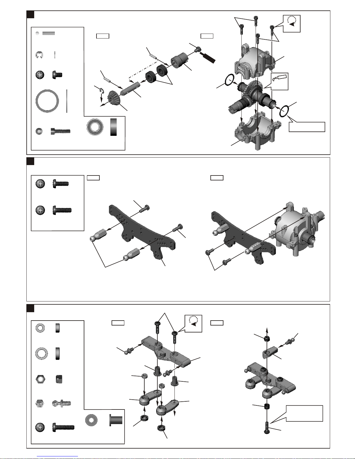
ASSEMBLY OF THE FRONT AND REAR BALL DIFF.
CHECKING BALL DIFF.
ASSEMBLY OF THE FRONT AND REAR BALL DIFF.
Step 2
37450
10x15mm Ball Bearing
37132
2.6x6x1mm Washer
.....x4
.....x4
.....x4
37137
9.6x11x0.8mm Ring
Builds two differentials for front and rear
35958
35958
5x8mm Ball Bearing
.....x4
37132
Screw2.6x25mm
.....x2
Apply
Grease
Apply
Grease
35958
37120
37110
37110
37145
40060
37132
37132
40060
2.6mm Nylon Nut
.....x2
Stabilize with
hex wrench or
screw driver.
Flat Head Screw Driver
Flat Head Screw Driver
* Turn to check.
phillips screw
driver
37450
37450
Step 1
Step 2Step 1
37137
37145
37148
38288
Step 1 Step 2 Step 3
37132
Parallel two Flat Head screw drives to the cap joint as show,
and rotate the differential gear to check if it slip.
If the differential gear slips, make a adjustments with a
phillips screw driver.
Use a phillips screw driver to tighten or loosen the ball
differential. Please note that the diff washer may be
damaged if the screw is over tightened or if diff gear slips
easily.
In the condition that the differential gear doesn't
slip, turn one of the cap joint and see if the other
cap joint turns in opposite direction.
Repeat step 2 several times until the gear turn
smoothly and without slip.
Builds two differentials for
front and rear.
(12 Pcs)