Ofs LC Fiber Optic Jumper Connectors User manual

Assembly Instructions for LC™
Fiber Optic Jumper Connectors
Epoxy Method for Singlemode and Multimode LC Simplex
and Duplex Jumper Connectors Used on Simplex and Duplex
1.6-mm MiniCordJumper Cords
640-252-054
Internal No.: 848 181 608
Issue 4
December 2001


Copyright 2001 OFSFitel
All Rights Reserved
Printed in U.S.A.
Table of Contents
1. General ................................................................................................................................. 1
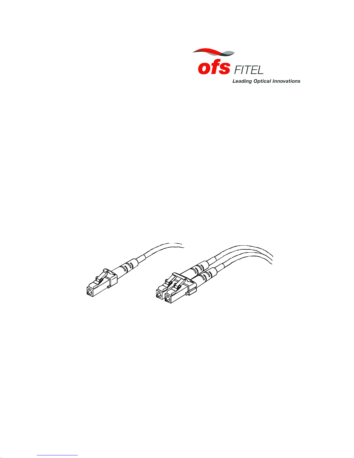
1.1 LC™Jumper Connectors................................................................................................. 1
1.2 Epoxy Consumables......................................................................................................... 1
1.3 Epoxy Tool and Upgrade Kits........................................................................................... 1
1.4 Ordering Information........................................................................................................ 2
2. Safety Precautions................................................................................................................. 2
3. Oven Preparation .................................................................................................................. 2
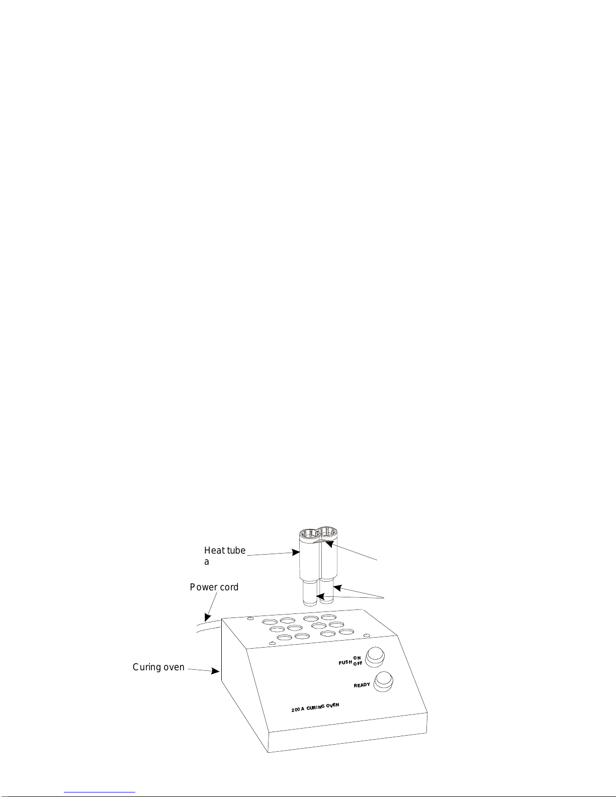
3.1 Set Up Curing Oven.........................................................................................................2
4. Cord Preparation ................................................................................................................... 3
4.1 Assemble Connector Components.................................................................................... 3
4.1.1 Simplex Applications on a Simplex Cord.................................................................... 3
4.1.2 Singlemode Simplex Applications on a Duplex Cord.................................................. 3
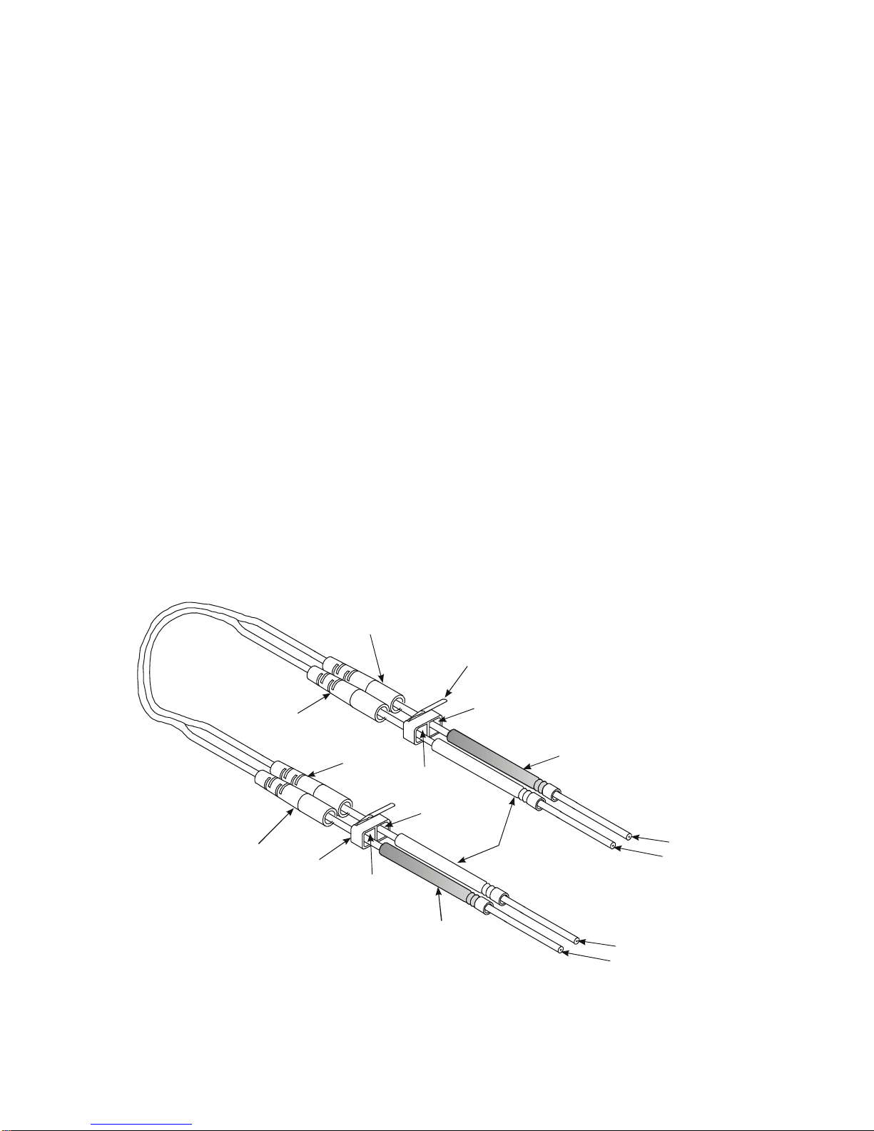
4.1.3a Duplex Applications on a Duplex Cord (with Regular Duplex Yoke).......................... 4
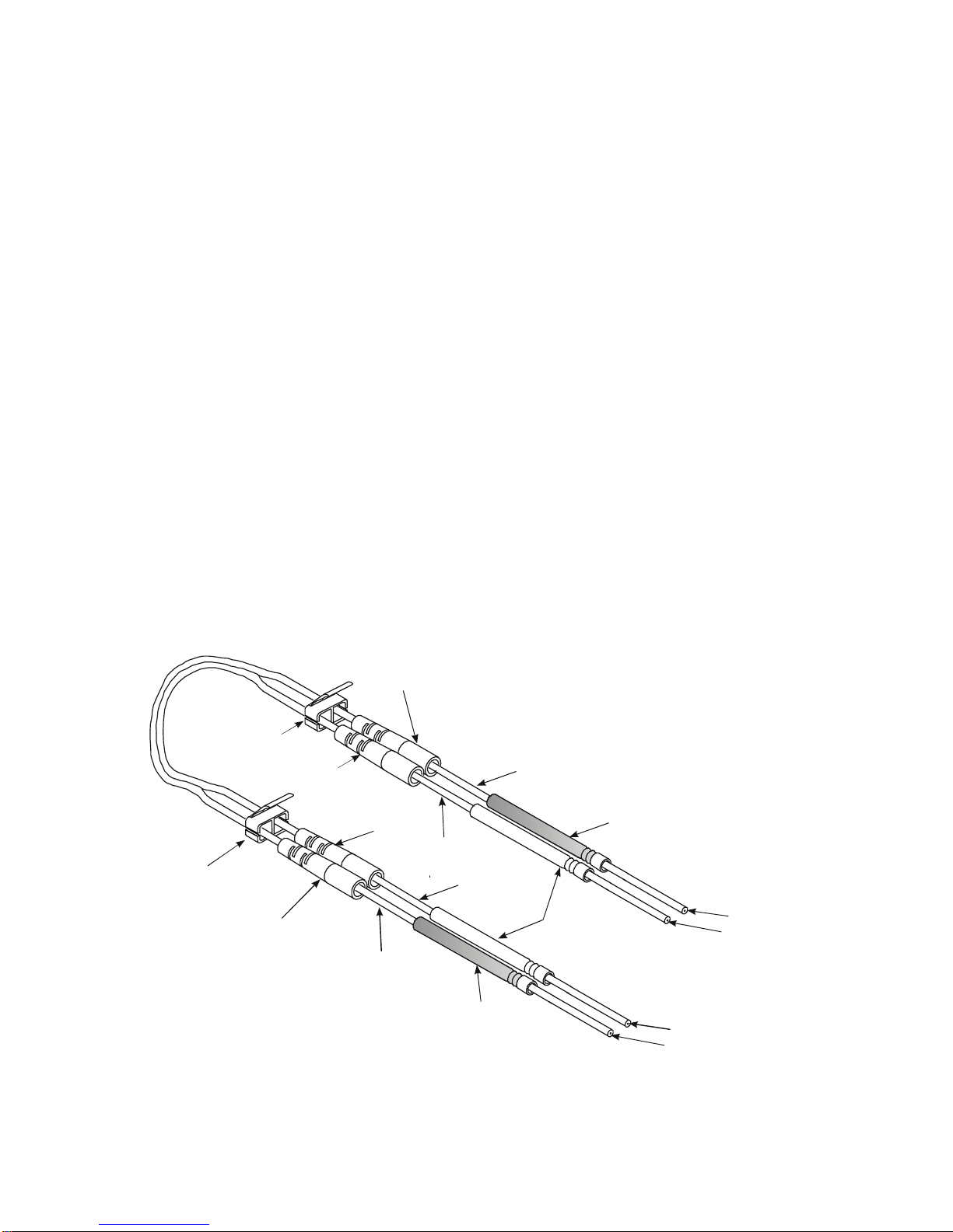
4.1.3b Duplex Applications on a Duplex Cord (with Replaceable Duplex Yoke)................... 5
4.2 Remove Outer Jacket and Trim Strengthening Yarn......................................................... 6
4.3 Remove Buffer and Fiber Coating.................................................................................... 7
4.4 Clean Stripped Fiber ........................................................................................................ 8
5. Epoxy Preparation................................................................................................................. 9
6. Connector Installation.......................................................................................................... 10
6.1 Prepare the Connector ................................................................................................... 10
6.2 Apply Epoxy................................................................................................................... 10
6.3 Insert Fiber..................................................................................................................... 11
6.4 Install Crimp Sleeve....................................................................................................... 12
6.5 Cure Connector Assemblies........................................................................................... 13
6.6 Cool Connector Assemblies............................................................................................ 13
6.7 Score the Fiber............................................................................................................... 13
6.8 Polish Fiber EndMultimode and Singlemode................................................................ 14
6.9 Repair Polishing Only...................................................................................................... 16
6.10 Final Assembly.............................................................................................................. 16
6.10.1 Simplex Connectors............................................................................................... 16
6.10.2a Duplex Connectors (with Regular Duplex Yoke) ................................................... 16
6.10.2b Duplex Connectors (with Replaceable Duplex Yoke)............................................ 17
7. Fiber Inspection and Ferrule Endface Geometry.................................................................. 18
7.1 Fiber Inspection............................................................................................................... 18
7.2 Ferrule Endface Geometry.............................................................................................. 19
8. Cleaning Instructions ........................................................................................................... 20
8.1 LC Connector................................................................................................................. 20
8.2 Adapter .......................................................................................................................... 20
9. Tuning Instructions .............................................................................................................. 21
9.1 General Information ....................................................................................................... 21
9.1.1 Tuning Index Tool.................................................................................................... 21
9.1.2 Tuning Wrench........................................................................................................ 21
9.1.3 Singlemode Offset Tuning Jumper........................................................................... 22
9.1.4 Hardcase with Foam Insert....................................................................................... 22
9.1.5 Instruction Sheet...................................................................................................... 22
9.2 Safety Information.......................................................................................................... 22
9.3 Tuning Procedure........................................................................................................... 23
10. Mount Adapter................................................................................................................... 27
11. Ordering Information.......................................................................................................... 28
12. Assistance Information....................................................................................................... 31


- -
- 1 -
1. General
1.1 LC™Jumper Connectors
The LC Fiber Optic Simplex and Duplex Jumper Connectors can be used to terminate simplex
and duplex 1.6-mm MiniCordjumper cords. It is intended for use in Central Offices, Local Area
Networks (LANs), and in patch cords for Premises Distribution Systems such as SYSTIMAX®
Structured Cabling Systems. The connector can also be used in computer backplane
connections, computer peripheral interconnections, device terminations, and other applications
where quality, small-size, high-density, low-loss, and a low-cost infrastructure are required.
Note: In addition to the simplex and duplex LC jumper connectors for 1.6-mm MiniCord
jumper cords, a Behind-The-Wall (BTW) connector is offered for 0.9-mm buffered fiber.
Installation of the BTW connector is not covered in this customer information product
(CIP). The BTW connector can be used to terminate Outside Plant (OSP) cables as well
as building cables.
When installed on typical fiber, the following performance should be obtained:
Multimode
Insertion loss (avg.) = 0.1 dB
Return loss ≥30 dB
Singlemode
Insertion loss (avg.) = 0.2 dB
Return loss ≥50 dB
1.2 Epoxy Consumables
Kit Type (Note) Kit Number Comcode Kit Includes
Multimode D-182983 108 340 811 Polishing paper, epoxy, and other materials
required to assemble 200 multimode connectors.
Singlemode D-182977 108 338 591 Polishing paper, epoxy, and other materials
required to assemble 200 singlemode connectors.
Note: Kits do not contain connectors, isopropyl alcohol, or nonozone-depleting canned air.
1.3 Epoxy Tool and Upgrade Kits
Kit Type (Note) Kit Number Comcode Kit Includes
Epoxy Tool Kit 1032B5 106 705 213 110-volt curing oven
Epoxy Tool Kit 1032B6 106 919 012 220-volt curing oven
Note: In addition to the tool kit, the D-182959 Upgrade Kit (108 262 569) is also required.
Connectors
Crimp Sleeves
Removable
Duplex Yoke
Cable Supports
Regular
Duplex Yoke
Connector
Crimp Sleeve
Cable Support
Simplex Jumper Components* Duplex Jumper Components
*Available one per package for simplex cord and two per package for SM duplex cord.

- 2 -
1.4 Ordering Information
Section 11 contains ordering information for LC connectors and kits.
2. Safety Precautions
• Safety glasses should be worn at all times while performing the installation procedures.
• Avoid skin contact with the epoxy.
• Place combustibles away from the curing oven when it is in operation. After the oven
has reached its operating temperature, the oven ports and heat tube assemblies are
extremely hot [266°F (130°C)]. Allow the oven and heat tube assemblies to cool before
handling or storing.
• Optical fibers may emit radiation if the far end is connected to a working laser or Light-
Emitting Diode (LED). Never view the fiber end of a cable or plug with the naked eye
or any optical instrument until absolute verification is established that the fiber is
disconnected from any laser or LED source.
3. Oven Preparation
3.1 Set Up Curing Oven
1. Place oven on a level surface and away from combustibles.
2. Connect the power cord to a power source (120 V 60 Hz AC for the 200A oven and 220 V 50
Hz AC for the 200Al international oven).
3. Locate the six heat tube assemblies (108 261 835) supplied with the D-182959 Upgrade Kit
(108 262 569).
4. Insert the heat tube assemblies into the heater ports.
Note: Be certain that the metal portion of each heat tube assembly is fully inserted into the
heater ports.
5. Push the ON/OFF switch to the ON position (lamp in switch illuminates).
Note: A READY lamp will illuminate when the oven reaches its operating temperature of
266°F (130°C).
Caution: After the oven reaches its operating temperature, the metal portion of the heat
tube assembly will be extremely HOT [266°F (130°C)]. Allow the oven and heat
tube assemblies to cool before handling and storing.
386+21
2))
5($'<
$&85,1*29(1
Curing oven
Power cord
Heat tube
assembly
Metal portion
of heat tube
assembly
Lifting lug (one on each
side of heat tube assembly)

- -
- 3 -
4. Cord Preparation
4.1 Assemble Connector Components
4.1.1 Simplex Applications on a Simplex Cord
1. Thread a cable support onto the simplex cord, narrow end first.
2. Thread a crimp sleeve onto the cord. The metal end of the crimp sleeve should be oriented
toward the end of the cord.
3. Repeat Steps 1 and 2 for the other end of the cord.
4.1.2 Singlemode Simplex Applications on a Duplex Cord
1. Split the jacket on the duplex cord into two separate cords at least 9 inches (230 mm) from
the end.
2. Thread a cable support onto each cord, narrow end first.
3. Determine the buffer color of each cord by looking into the end of the cordage. The duplex
cord should have a blue buffer and an orange buffer.
4. Thread a yellow crimp sleeve on the cord with the blue buffer and a white crimp sleeve on
the cord with the orange buffer. The metal end of the crimp sleeve should be oriented toward
the end of the cord.
5. Repeat Steps 1 through 4 for the other end of the cord.
Narrow end of
cable support
Cable support
Crimp sleeve
Metal end of
crimp sleeve
Cable support
Crimp sleeve
(yellow)
Crimp sleeve
(white)
Cable support
Blue buffer
Orange buffer

- 4 -
4.1.3a Duplex Applications on a Duplex Cord (with Regular Duplex Yoke)
1. Split the jacket on the duplex cord into two separate cords at least 9 inches (230 mm) from
the end.
2. Thread a cable support onto each cord, narrow end first.
3. Determine the buffer color of each cord by looking at the end of the cordage. The duplex
cord should have a blue buffer and an orange buffer.
4. Locate the Bchannel opening on the duplex yoke.
5. At the first end, thread the cord with the blue buffer through the Bchannel opening.
6. Locate the Achannel opening on the duplex yoke.
7. Thread the cord with the orange buffer through the Achannel opening.
8. Place a yellow crimp sleeve on the cord with the blue buffer and a white crimp sleeve on the
cord with the orange buffer. The metal end of the crimp sleeves should be oriented toward
the end of the cord.
9. On the opposite end of the duplex cord, split the jacket into two separate cords at least 9
inches (230 mm) from the end.
10. Thread a cable support onto each cord, narrow end first.
11. Determine which cord has the blue buffer and which cord has the orange buffer.
12. Locate the Achannel opening on the duplex yoke.
13. Thread the cord with the blue buffer through the Achannel opening.
14. Locate the Bchannel opening on the duplex yoke.
15. Thread the cord with the orange buffer through the Bchannel opening.
16. Place a yellow crimp sleeve on the cord with the blue buffer and a white crimp sleeve on the
cord with the orange buffer. The metal end of the crimp sleeves should be oriented toward
the end of the cord.
Duplex yoke
Cable support
Crimp sleeve
(yellow)
Cable support
Blue buffer
Orange buffer
Duplex yoke
B
channel
opening
B
channel
opening
A
channel
opening
A
channel
opening
Cable support
Crimp sleeve
(yellow)
Crimp sleeve
(white)
Cable support
Blue buffer
Orange buffer

- -
- 5 -
4.1.3b Duplex Applications on a Duplex Cord (with Replaceable Duplex Yoke)
1. Split the jacket on the duplex cord into two separate cords at least 9 inches (230 mm) from
the end.
2. Determine the buffer color of each cord by looking at the end of the cordage. The duplex
cord should have a blue buffer and an orange buffer.
3. Locate the Bchannel opening on the duplex yoke.
4. At the first end, thread the cord with the blue buffer through the Bchannel opening.
5. Locate the Achannel opening on the duplex yoke.
6. Thread the cord with the orange buffer through the Achannel opening.
7. Thread a cable support onto each cord, narrow end first.
8. Place a yellow crimp sleeve on the cord with the blue buffer and a white crimp sleeve on the
cord with the orange buffer. The metal end of the crimp sleeves should be oriented toward
the end of the cord.
9. On the opposite end of the duplex cord, split the jacket into two separate cords at least 9
inches (230 mm) from the end.
10. Determine which cord has the blue buffer and which cord has the orange buffer.
11. Locate the Achannel opening on the duplex yoke.
12. Thread the cord with the blue buffer through the Achannel opening.
13. Locate the Bchannel opening on the duplex yoke.
14. Thread the cord with the orange buffer through the Bchannel opening.
15. Thread a cable support onto each cord, narrow end first.
16. Place a yellow crimp sleeve on the cord with the blue buffer and a white crimp sleeve on the
cord with the orange buffer. The metal end of the crimp sleeves should be oriented toward
the end of the cord.
Removable
Duplex yoke
Cable support
Crimp sleeve
(yellow)
Cable support
Blue buffer
Orange buffer
Bchannel
opening
Bchannel
opening
Achannel
opening
Achannel
opening
Cable support
Crimp sleeve
(yellow)
Crimp sleeve
(white)
Cable support
Blue buffer
Orange buffer
Removable
Duplex yoke

- 6 -
4.2 Remove Outer Jacket and Trim Strengthening Yarn
1. Locate the template and pen provided in the D-182959 Upgrade Kit (108 262 536).
2. Measure and mark outer jacket at 1.125 inches (28.5 mm) and at 1.375 inches (34.9 mm)
from the end.
3. Use the 700A stripping tool to remove outer jacket at the 1.125 inches (28.5 mm) mark.
4. Lightly twist the strengthening yarn into one bundle and use scissors to cut yarn flush with
the end of the outer jacket.
1.375 inches
(34.9 mm)
1.125 inches
(28.5 mm)
Number 1
notch
Outer jacket
being removed
Stripping tool
(blue handles)
Buffered
fiber
Outer jacket
Cut strengthening yarn
flush with outer jacket

- -
- 7 -
5. Use the 700A stripping tool to remove outer jacket at the 1.375 inches (34.9 mm) mark. This
will expose 0.25 inch (6.3 mm) of yarn.
6. Flare the shortened strengthening yarn evenly around the cable. The brush from the 1026A
stripper tool can be used.
4.3 Remove Buffer and Fiber Coating
Note: Refer to 1026A Heat-Strip Tool operating instructions for heat-strip tool setup.
1. Locate the 1026A Heat-Strip Tool (105 514 764) provided in the 1032B5 Tool Kit
(106 705 213) or in the 1032B6 Tool Kit (106 919 012).
2. Locate the gold LC stripper guide tube (108 262 577) provided in D-182959 Upgrade Kit.
3. Install the heat-strip tube into the heat-strip tool making sure the heat-strip tube is fully
inserted into the heat-strip tool.
4. Insert buffered fiber into the guide tube until the jacket and strengthening yarn hit the
appropriate stop inside the guide tube.
Note: Do not force the cord into the guide tube. If the buffer does not go through the guide
tube easily, trim 0.03125 inch (0.794 mm) from end of buffer. The end of the buffer
occasionally becomes flattened when the cord is initially cut. The buffered fiber
should protrude approximately 0.55 inch (14 mm) into the guide tube.
Caution: Proper stripping lengths and procedures are required for best connector pull-proof
performance.
Number 1
notch
Outer jacket
being removed
Stripping tool
(blue handles)

- 8 -
5. Close the handles of the heat-strip tool and wait 6 to 10 seconds for the softening of the
buffer to occur.
6. Wrap the cord around your index finger and pull the fiber from the tool with one smooth and
straight motion.
Note: Wrapping the cord around your index finger may prevent the buffered fiber from
slipping out of the jacket during the stripping operation.
Caution: The buffer must not be allowed to move within the cord while stripping. Do not
strip additional buffer length if buffer pulls from cordage. Buffer will normally
push back into cord during connector plug assembly.
4.4 Clean Stripped Fiber
1. Saturate a wipe with isopropyl alcohol (>91% 2-propanol + water).
2. Start at the coating end and wipe toward the fiber end.
Note: If residue remains on the fiber, use a clean wipe saturated with isopropyl alcohol to
wipe the fiber again.
3. Place the prepared cord into the grooves of the 971A-2 holder block to avoid breaking or
contamination of the fiber (holder blocks are provided in the D-182959 Upgrade Kit).
0.55 inch
(14 mm)
0.25 inch
(6.3 mm)
Partial view
of a 971A-2
holder block
Prepared fiber in a
1.6-mm groove

- -
- 9 -
5. Epoxy Preparation
The supplied epoxy comes in a two-part package. A divider separates the resin from the
hardener. The divider must be removed to allow the epoxy to be mixed. The epoxy is then
loaded into a syringe. Both the epoxy package and the syringe are furnished with the D-182977
(108 338 591) and the D-182983 (108 340 811) Kits of Consumables. See ordering information
in Section 10 of this manual.
Caution: Avoid contact of epoxy with skin.
1. Locate the epoxy package in the D-182977 or the D-182983 consumables kits..
2. Remove the divider between the resin and the hardener.
3. Mix the epoxy using the divider.
Note: The epoxy must be thoroughly mixed until both parts are blended into a smooth
uniform color.
4. Locate the syringe in the D-182977 or the D-182983 consumables kits.
5. Place the syringe tip on the syringe and twist to lock in place.
6. Remove the plunger from the syringe.
7. Fold the epoxy package in half and cut off one of the package corners.
8. Squeeze the mixed epoxy into the syringe.
Note: A ¾-inch (19 mm) length of epoxy will be enough for about 50 connectors.
9. Replace the plunger into the syringe.
10. Remove air pockets from the syringe by holding the syringe tip upward and ejecting epoxy
until the air pockets are removed.
Divider used to
mix epoxy
Epoxy being
loaded into
syringe
Syringe

- 10 -
6. Connector Installation
Connectors are provided in packages which must be ordered by product codes (see Section 10
for LC Connector Product Codes). Each connector is fitted with a white dust cap to protect the
connector tip from damage and contamination. During the connector installation process a holder
(provided in the D-182959 Upgrade Kit) is used to protect the fiber protruding from the connector
tip and to aid in the handling of the small connectors.
6.1 Prepare the Connector
1. Locate the connector to be installed and remove the white dust cap.
2. Locate a connector holder from the upgrade kit and snap the connector into the holder.
6.2 Apply Epoxy
Epoxy is injected into two areas of the connector: (1) inside of the ferrule and (2) at the back of
the ferrule. The syringe is first used to inject epoxy into the ferrule. This epoxy bonds the
stripped fiber to the ferrule. Before removing the syringe from the connector, epoxy must next be
deposited at the back of the ferrule. This epoxy bonds the buffer at the back of the ferrule.
DO NOT apply an excessive amount of epoxy to either the ferrule or at the back of the ferrule.
Note:
Simplex connector shown.
Tip of ferrule
(face)
Ferrule
Back of ferrule Back of
connector
Small tube
Simplex connector
Duplex connector
Trigger
(no trigger)
Latch Latch
Connector holder
or

- -
- 11 -
1. Visually locate the small tube inside the back of the connector.
2. Carefully insert the tip of the syringe into the small tube until it bottoms.
Caution: In the following step, do not apply excess epoxy to the connector tip of the ferrule.
3. Inject epoxy into the ferrule by slowly pressing the syringe plunger until the epoxy just
appears at the connector tip (face of the ferrule).
4. Deposit epoxy at the back of the ferrule by pulling the tip of the syringe back slightly and
momentarily injecting a small amount of epoxy at the back of the ferrule.
Caution: When removing syringe from the connector in the following step, do not allow
epoxy on syringe tip to contaminate the small tube or the back of the connector.
5. Release pressure on plunger, wait a moment, and then remove the syringe from the
connector.
6.3 Insert Fiber
1. Remove prepared fiber from holder block.
2. Insert the exposed fiber into the small tube inside the connector and carefully feel for the
opening in the ferrule.
Note: Rotating the fiber or the connector assembly may help to locate the opening.
Caution: Only perform the following step once.
3. When the fiber is seated, pull it back slightly and watch for fiber movement at the tip of the
connector to make sure the fiber is not broken.
4. Reposition the fiber back into the connector.
Syringe
Holder
Connector
Cutaway view
showing small tube
Connector
Fiber Buffered
fiber
Strengthening
yarn Prepared
cable
Holder

- 12 -
6.4 Install Crimp Sleeve
1. Slip the cable crimp sleeve assembly over the back of the connector while capturing the
strengthening yarn.
2. Using the 1510LC crimping tool (supplied in the D-182959 kit), place the square edge of the
connector against one edge of the crimp jaw with the crimp sleeve assembly lying through
the crimp jaws.
Caution: Crimping the crimp sleeve more than once can weaken the connector.
CRIMP ONLY ONCE.
3. Apply pressure until crimping tool completely closes and automatically opens.
4. Store crimped connector vertically in the holder block until up to 12 simplex or 6 duplex
connectors have been crimped.
971A-2 holder blocks
Note:
D-182959 Upgrade Kit provides
two 971A-2 holder blocks.
Crimped
connector

- -
- 13 -
6.5 Cure Connector Assemblies
1. When the desired number of connectors has been prepared, place the holder block next to
the preheated oven.
2. Place the crimped connector assemblies into the heat pipes.
3. Ensure that the connector assemblies are sitting at the bottom of the heat pipes.
4. Remove the assemblies from the heat pipes after they have cured for 10 minutes.
6.6 Cool Connector Assemblies
1. Place cured assemblies back into the holder block to cool.
2. For simplex connectors: Push the cable supports onto the connector. The cable support is
properly installed when the cable support contacts the back of the connector. Do NOT twist
or forcibly push the cable support onto the connector. Twisting or forcibly pushing the
cable support onto the connector may damage the fiber.
For duplex connectors: Allow the connector holder assemblies to completely cool in the
holder blocks. Do not install the cable support at this time.
6.7 Score the Fiber
1. Remove the connector from the connector holder.
2. Obtain the 975A cleaving tool from the 1032B5 Tool Kit or from the 1032B6 Tool Kit.
Note: In the following step, score the fiber as close to the ferrule as possible while at the
same time being careful not to break the fiber.
3. Place the cleaving tool against the ferrule and exposed fiber.
4. Using one stroke of the cleaving tool, gently score the exposed fiber.
5. Remove the exposed fiber by gently pulling straight away from the cable.
Note: If fiber did not readily pull off, score fiber again on opposite side and gently pull fiber.
6. Dispose of the fiber scraps in a safe manner.
Note: The adhesive surface on a piece of tape is a convenient place to hold fiber piece
until disposal.
Cleaving
tool
Fiber
Use
stroke to
score fiber
ONE
Connector

- 14 -
6.8 Polish Fiber EndMultimode and Singlemode
Caution: Contaminates on polishing materials can cause scratches on the end face of the
fiber/ferrule. Throughout the entire polishing process, keep work area and all polishing
materials clean. Clean polishing papers between each step using a wipe moistened
with alcohol. This is especially true for the type F (yellow) and type K (gray) polishing
papers because they can be repeatedly cleaned and reused.
Note 1: Tables A for multimode and B for singlemode provide a quick reference for polishing.
Note 2: Cut one sheet of type J polishing paper (purple) into four pieces.
Step 1. Remove Fiber Stub
a. In one hand, hold one of the cut pieces of type J polishing paper (dull side down).
b. In the other hand, hold the connector with the tip pointing upward.
Note: When performing the following step, be careful not to break the fiber stub.
c. Air polish using light circular motions about 1 inch in diameter; carefully polish off fiber stub.
d. Use canned air to clean the back and front of a full piece of type J polishing paper (purple).
e. Saturate a wipe with isopropyl alcohol (>91% 2-propanol + water).
f. Obtain a glass plate and a polishing tool (T2000A or T2001A) from D-182959 Upgrade Kit.
g. Clean the glass plate and polishing tool with the saturated wipe.
h. Use canned air to blow dry the glass plate and the polishing tool.
i. Insert the LC connector into the T2000A or T2001A polishing tool.
Step 2. Remove Excess Epoxy
a. Place one clear spacer sheet on the glass plate, then place a sheet of type J polishing paper
(purple) on the glass plate with the dull side up.
b. Gently place the polishing tool and connector onto the polishing paper.
Note: In the following step, you should not feel any drag between the fiber and the paper.
Start with light pressure and use figure-8 strokes that are approximately 2 inches high
and 1 inch wide. The figure-8 strokes must be well rounded to ensure complete
removal of the epoxy from the end of the ferrule.
c. Using light pressure, polish the connector for 20 figure-8 strokes.
Danger: Optical fibers may emit radiation if the far end is connected with a working laser or
Light-Emitting Diode (LED). Never view the fiber end of a cable or plug with the
naked eye or any optical instrument until absolute verification is established that
the fiber is disconnected from any laser or LED source.
d. Using a 7X eye loupe or LC microscope supplied in the D-181259 Upgrade Kit, check the tip
of the ferrule. No excess epoxy should surround the fiber.
T
ypeJpolishing
p
aper(purple)with
d
ullsidedown

- -
- 15 -
Note: If excess epoxy is found, continue to use type J polishing paper (purple) to remove
the excess epoxy.
Step 3. Dome Ferrule End
a. Place the following consumables on the glass plate: one white foam pad, five clear spacers,
and on top place a sheet of type F polishing paper (yellow).
Note: Type F polishing paper can be reused by cleaning with alcohol and wipes as needed.
b. Using light pressure, polish the connector for 20 figure-8 strokes.
Note: Step 3 concludes the polishing procedure for multimode fibers. Steps 4 and 5 are to
be performed for singlemode fibers only.
Step 4. Improve Dome Surface Finish
a. Replace the sheet of type F (yellow) polishing paper with a sheet of type K (gray) dull side
up. Leave the five clear spacers and foam pad on glass plate.
b. Polish the connector for 20 additional figure-8 strokes.
Step 5. Singlemode Final Polish
a. Remove all polishing material from glass plate and replace with type L felt polishing pad
(purple).
Note: Step 5b is critical for excellent return loss. Perform carefully by guiding the polishing
tool and plug slowly and gently, never increasing pressure.
b. Dampen one-fourth of sheet with distilled water (do not flood). Buff polish 20 light figure-8
strokes, approximately 3 inches high and 1 ½inches wide.
c. Clean fiber end with wipe dampened with water, then with a second wipe dampened with
alcohol.
d. The felt can be stored damp in a clean plastic bag and reused. The glass plate should be
immediately cleaned with water and dried completely before storage to prevent polishing
residue from permanently drying on glass plate.
Note: Step 5 provides the necessary steps for high performance return loss. Type L felt
polishing pad (purple) is imbedded with ultrafine polishing material.
Type J polishing
paper (purple) with
dull side up
Polishing paper
Foam pad (white)
Five clear spacers
(under polishing paper)
Glass plate

- 16 -
Table A. Overview—Polishing Multimode
Step Polishing Materials
No. of Figure-8
Strokes Notes
1 Type J, purple As Required Air polish to remove fiber stub.
2 Type J, purple
One spacer (clear) 20, then as
required Dry polish on glass plate to
remove excess epoxy.
3 Type F, yellow
Five spacers (clear), foam pad 20
Dry polish on glass plate to
dome ferrule.
Repair
polish, only
if needed
Type F, yellow
One spacer (clear) As required to
remove flaw Repair polish. Dry polish on
glass plate. After flaw is
removed, repeat Step 3.
Table B. Overview—Polishing Singlemode
Step Polishing Materials
No. of Figure-8
Strokes Notes
1 Type J, purple As Required Air polish to remove fiber stub.
2 Type J, purple
One spacer (clear) 20, then as
required Dry polish on glass plate to
remove excess epoxy.
3 Type F, yellow
Five spacers (clear), foam pad 20
Dry polish on glass plate to
dome ferrule.
4 Type K, gray
Five spacers (clear), foam pad 20
Dry polish on glass plate to
improve dome surface finish.
5 Type L, purple felt 20 light
Dampen felt with distilled water
for final finish.
Repair
polish, only
if needed
Type F, yellow
One spacer (clear) As required to
remove flaw Repair polish. Dry polish on
glass plate. After flaw is
removed, repeat Step 3.
6.9 Repair Polishing Only
1. Place a sheet of type F paper and one clear spacer over the glass plate.
2. Using little or no pressure, polish the connector until the flaw has been removed.
3. Repeat Step 3 in Section 6.8.
Note: Do not over polish. Approximately one-third of the chamfer length can be polished
away. This concludes the repair procedure for multimode fibers.
4. For singlemode fibers only, repeat Steps 4 and 5 in Section 6.8.
6.10 Final Assembly
6.10.1 Simplex Connectors
1. Ensure that connector has been polished and the end finish is acceptable.
2. Cover the end of the connector with the white dust cap supplied with the connector.
6.10.2a Duplex Connectors (with Regular Duplex Yoke)
1. Ensure that each connector has been polished and the end finish is acceptable.
2. Snap the duplex connectors into the LC adapter supplied in the D-182959 (108 262 569)
Upgrade Kit.
Note: The LC adapter is a temporary aid used in installing the final components of the
connector assembly.
3. Ensure that the cords are not twisted.
4. Slip duplex yoke over the cable and onto the back of the connectors until it snaps into place.
Table of contents