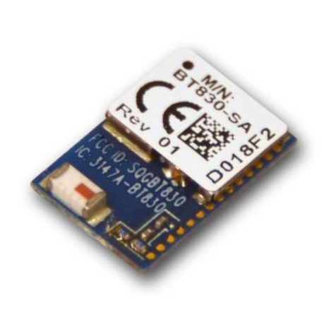
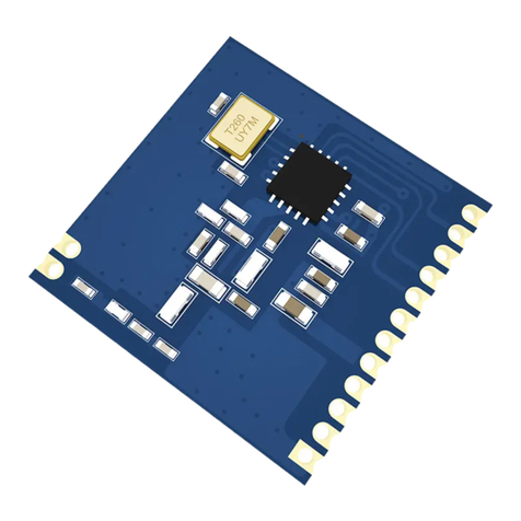
OGEMRAY GWF-3M08 User manual

USB WIRELESS MODULE
GWF-3M08
User’s Manual
(FCC Version 2.0)

User’s Manual Wireless Module
Page 1 of 22
FCC Statement
Federal Communication Commission Interference Statement
This equipment has been tested and found to comply with the limits for a Class B digital device, pursuant to Part
15 of the FCC Rules. These limits are designed to provide reasonable protection against harmful interference in a
residential installation. This equipment generates uses and can radiate radio frequency energy and, if not installed
and used in accordance with the instructions, may cause harmful
Interference to radio communications. However, there is no guarantee that interference will not occur in a particular
installation. If this equipment does cause harmful interference to radio or television reception, which can be
determined by turning the equipment off and on, the user is encouraged to try to correct the interference by one of
the following measures:
- Reorient or relocate the receiving antenna.
- Increase the separation between the equipment and receiver.
- Connect the equipment into an outlet on a circuit different from that to which the receiver is connected.
- Consult the dealer or an experienced radio/TV technician for help.
IMPORTANT NOTE:
Any changes or modification to this unit not expressly approved by the party responsible for
compliance could void the user’s authority to operate the equipment.
FCC RF RADIATION EXPOSURE STATEMENT:
This module must be installed and operated in accordance with provided instructions and the antenna used for this
transmitter must be installed to provied a separation distance of at least 20 cm from all persons and must not be
co-located or operating in conjunction with any other antenna or transmitter. End-uses and installers must be provide
with antenna installation instructions and transmitter operating conditions for satisfying RF exposure compliance.
LABELING REQUIREMENTS:
1. This device complies with Part 15 of the FCC rules. Operation is subject to the following two conditions (1)
this device may not cause harmful interference, and (2) this device must accept any interference received,
including interference that may cause undesired operation.
2. Host device of OEM integrator must be labeled with:
CONTAINS TX FCC ID: QR4WF5370M08
INFORMATION FOR THE OEM INTEGRATORS:
The following statements must be included with all versions of this document supplied to an OEM or integrator,

User’s Manual Wireless Module
Page 2 of 22
but should not be distributed to the end user:
1. This module is intended for OEM integrators only.
2. Please refer to the full Grant of Equipment document for other restrictions.
3. This module must be operated and used with a locally approved access point.
USER’S MANUAL OF THE END PRODUCT:
In the user’s manual of the end product, the following information in a prominent location must include:
1. To comply with FCC RF radiation exposure requirements, the antenna(s) used for this module must not be
co-located or operating in conjunction with any other antenna or transmitter.
2. The end user has to be informed: 1). to keep at least 20 cm separation with the antenna while this end
product is installed and operated. 2). the FCC radio-frequency exposure guidelines for an uncontrolled
environment can be satisfied. 3). any changes or modifications not expressly approved by the manufacturer
could void the user’s authority to operate this equipment.
3. If the size of the end product is smaller than 8x10cm, then additional FCC part 15.19. statement is required
to be available in the user’s manual: this device complies with part 15 of FCC rules. Operation is subject to
the following two conditions: (1) this device may not cause harmful interference and (2) this device must
accept any interference received, including interference that may cause undesired operation.
4. Any changes or modifications not expressly approved by the manufacturer could void the user’s authority to
operate this equipment.

User’s Manual Wireless Module
Page 3 of 22
1. Introduction
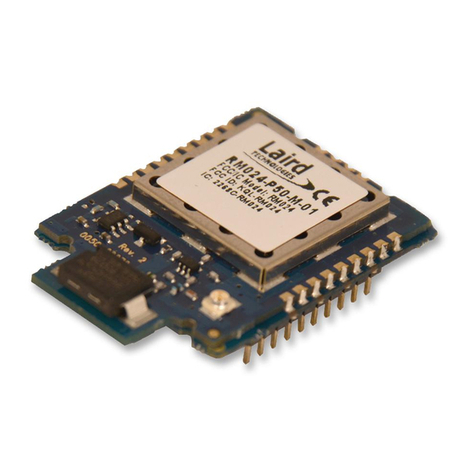
GWF-3M08 is a WLAN module supporting IEEE 802.11 b/g/n standards with max 7-pin
connector supporting USB 2.0 /1.1 interfaces. This is a small form factor and low cost compact
WLAN module designed for the wireless connectivity of products with embedded system.
This module operates in 2.4GHz ISM frequency band, it applies a highly integrated
MAC/BBP and RF single chip RT5370 with 150Mbps PHY rate supporting. This module can be
built-in other embedded applications such as IP Camera, IP set top box, GPS, Internet radio
apparatus, it can be directly soldered on a main PCB.
1.1 Features
802.11b: 1, 2, 5.5, 11Mbps; 802.11g: 6, 9, 12, 24, 36, 48, 54Mbps
802.11n: (20MHz) MCS0-7, Support up to 72Mbps
(40MHz) MCS0-7, Support up to 150Mbps
OFDM, Peak rate 150Mbps, Peak throughput 90Mbps.
Security support for 64/128 WEP, WPA, WPA2, TKIP, AES
Operates in 2.4GHz frequency bands. Power Management
WPS and TX external control, WiFi-direct supported.
2. Product Information
2.1 Typical Specification Overview
Standards IEEE802.11b/g/n (1T1R mode)
Operating Frequency 2.412GHz ~ 2.462GHz.
Protocols 802.11b: CCK, QPSK, BPSK, 802.11g/n: OFDM
Antenna Built-in On Board PCB antenna
Security WPA/WP2/WPAI, 64/128/152-bit WEP, WPS
Transmit Output Power
(Typical value to antenna)
11b: 17±1.0dBm @ 11Mbps; 11g: 14±1dBm @ 54Mbps
802.11n: (HT20), 12+/-1dBm, 802.11n: (HT40), 12+/-1dBm
Receive Sensitivity
(Typical value after
antenna)
11b: -84dBm @ 11Mbps; 11g: -72dBm @ 54Mpbs.
802.11n: (HT20), -68dBm@MSC7, (HT40),-67dBm@MSC7
Operating Voltage 5.0V or 3.3VDV± 5%
Operating Current(OFDM,
54Mbps)5.0V power input,<150mA; 3.3V power input.<250mA
Bus Interface USB 2.0/1.1
USB Interface Max: 7 pins, 2.0 mm pitch pin header. Or Max: 7 pins semi-hole.
User’s Manual Wireless Module
Page 4 of 22
2.2 Hardware Information
2.2.1 General view
Fig 1
2.2.2 Block Diagram
Fig 2. With onboard PCB antenna used
2.2.3 Mechanical Information
A. Physical Dimensions:
a. Semi-holes with 2.0mm pitch (onboard PCB antenna).
Fig 3.
RF
Receiver
RF
Transmitter
Baseband
MAC/
Packet
Buffer/
Encrption
Engine
DATA- USB
Interface
VCC(3.3V)
DATA+
GND
RT5370
RF
Front
End
USB
Interface
USB WiFi Module
TX CONTROL
EXTERNAL LED
3.3V/1.5V5V/3.3V
PCB antenna
2412~2462MHz
WPS CONTROL

User’s Manual Wireless Module
Page 5 of 22
b. Top side 7-pin pin header with 2.0mm pitch
Fig 4
c. Bottom side 7-pin pin header with 2.0mm pitch
Fig 5.

User’s Manual Wireless Module
Page 6 of 22
d. 90 degree 7-pin pin header with 2.0mm pitch
Fig 6.
B. Pin Descriptions:
Notes:
1. TX terminal must be pulled up with an external resistor (4.7K ohm) to high level.
2. LED terminal output 3.3V LED blink signal. To limit LED current, a series 330 ohm or
other value resistor should be connected.
3. WPS terminal is internally pulled up with an onboard 4.7K ohm resistor to 3.3VDC.
Pin Name Descriptions
1 TX RF ON/OFF control; low level activated to OFF
2 VCC 5.0VDC or 3.3VDC, +/-5%
3 UD- USB data-
4 UD+ USB data+
5 GND Ground
6 LED Indicate module working status
7 WPS External to activate WPS function. Low level activated.

User’s Manual Wireless Module
Page 7 of 22
C. RF signal input and output:
on-board PCB antenna.
Fig 7
The onboard antenna is designed with tiny space which affects the signal performance. If
the onboard antenna does not satisfy user’s application, please use other external antenna.
Warning:
Should an external antenna rather than the built-in PCB antenna be used, the
OEM integrator is responsible for testing their end-product for any additional
compliance requirements required with this module installed.
2.3 Software and system Information
Operation System CPU Supplier Driver
Linux 2.4/2.6 ARM, MIPSII Available
Windows XP/Vista/7 X86 Platform Available
Windows CE 5.0/6.0 ARM, MIPSII Available
Mac OS X
10.3/10.4/10.5/10.6/10.7 N/A Available
2.4. Design Concerns:
2.4.1 Power supply:
1) The input power can be 5.0VDC or 3.3VDC, please mentioned it when place an order.
2) The operation current of 5.0VDC power input will be different with that of 3.3V power
input. The external power shall be well designed with enough current capacity.
3) Should 3.3VDC power be selected, please be sure it’s clean with low ripple; otherwise,
the EMI or RF performance might be deteriorated.
2.4.12 Using pin headers:
1) The pins can be less than 7 pins, but at least the VCC, UD-, UD+, GND must be
applied for USB interface communication.
2) Should the pin header connection be applied, please still keep enough metallic clear
space around the antenna end of the module, this gives better signal performance.
2.4.2 Using semi-holes:
1) When the module is designed to be soldered on a main PCB board directly, the area
under the antenna end of the module should be keep clear of metallic components,
connectors, vias, traces and other materials that can interfere with the radio signal. The
recommended clear space requirements are refer to Fig 8 and Fig 9.

User’s Manual Wireless Module
Page 8 of 22
2) The module is not recommended using reflow oven process, hand soldering is
suggested.
2.4.2 Clear place to use the module:
The following drawing shows a recommended footprint which can be a reference for a
main PCB design.
The clear space requirement for onboard antenna is suit for either pin header or
semi-holes connection application.
Fig 8
Fig 9.

User’s Manual Wireless Module
Page 9 of 22
3. Software Installation
Mentioned: The following information just describes the procedures of software installation
under Windows system. As for those under Linux, Android, the OEM integrator must do their
own specific embed system programming, the procedures is entirely different.
To install the driver of the module, please use administrator user account to login before the
following steps:
Tips: the latest original drivers can be down loaded from the website of Ralink chipset
manufacturer. The current website is http://www.ralinktech.com/en/04_support/support.php?sn=500
To find a correct driver, please identify the chipset type applied in the module you have.
For Windows XP:
The system will detect a new hardware has been added, and start the “Found New
Haerdware Wizard”. Click on “Cancel”.
1. Please insert the disc into your CD-ROM drive. The disc should auto start, dispaying
the following window, If it does not start due to the system setting, open the browser
window, find the autorun.exe file in your CD-ROM folder, click to run it.
2. Ralink has integrated all the 54Mbps 802.11b/g ,150Mbps or 300Mbps 802.11n driver
into one file. Click to run the “Driver Installation”
Notes: Because Ralink often updates software, the drivers contained in the disc
might be changed without prior notice.
3. Follow the instructions and prompts of the “InstallShield Wizard” to finish the driver
installation:
a. Select the “I accept the terms of the license agreements”, then click the “Next”.
b. There shows a setup type window, you can select “Install driver only” or “Install driver
and Ralink WLAN utility” and then click the “Next”.

User’s Manual Wireless Module
Page 10 of 22
Tips:
1).The Windows XP utilizes a "Wireless Zero Configuration( WZC)" Service built into
the operating system. Many wireless network module cards utilize this service.
2). Ralink- the chipset manufacturer has developed a utility for setting up wireless
connection. If you select this item, you can switch between the Windows XP’s WZC
service and the Ralink WLAN utility service later.
c. Click the “Install” to confirm the installation, there shows the installation progress.

User’s Manual Wireless Module
Page 11 of 22
d. Click “finish” to finish the driver installation.
For Windows 7:
Once the wireless USB module be plugged into an USB port, the following message will
appear on screen.
The following installation procedures are similar to those of Windows XP. Please
refer to the installation steps for Windows XP.
4. Wireless Connection
For Windows XP:
1. After finishing driver installation, insert the USB module to Notebook or PC that supports

User’s Manual Wireless Module
Page 12 of 22
USB 2.0/1.1 interface.
Remarks: Make sure to connect the module to an USB port on your computer
directly rather than an USB hub. Although it might work when connecting with an
USB hub, the likelihood of configuration problems will be higher.
2. The system shows a wireless utility icon in the Windows system tray, which locates in
the bottom-right corner of your computer screen, and pops up a message that indicates
a new hardware is found and installed, something like this:
Before you begin, ensure WZC is enabled, by right-clicking on the Ralink icon
in the task bar in the bottom right hand corner of your screen.
In the menu that appears, select "Use Zero Configuration as Configuration Utility" to
use Windows' wireless management feature, Windows Zero Configuration (WZC), to
manage your Ralink Wireless Module.
1. Right click the icon and then select “View Available Wireless Networks” to launch the
utility, the Wireless Network Connection window appears and displays your wireless
network listed with the SSID you chose.
Notes: Before configuring your WiFi access, you need to have your network’s SSID
(service set identifier), security key and authentication type handy. Check the
documentation coming with your router, ask your network administrator to get the
information.
2. If you don't see your network, click “Refresh network list” in the upper left corner. If you
are locating within the valid range of hotspots or wireless routers, all available networks
will be recognized and listed automatically. Click your preferred network, and then click
“Connect” in the lower right corner.
Should the service " Wireless Zero Configuration ( WZC)" be applied.

User’s Manual Wireless Module
Page 13 of 22
3. If the network security key hasn’t been inputted before, Windows XP prompts you to
enter the network’s security key to access the wanted SSID. Type the encryption key
that you wrote down earlier in both the Network key and Confirm network key boxes,
and then click “Connect”.
Tips: If there are free hotspots, simply select the network you want from the list
displayed, then click Connecting. It tries to launch your Internet browser—you should
be connected to the Internet.
If there is a pay hotspot, signing in or up will require either to enter your login
information-if you‘re an existing customer, or to enter your credit card information for
payment, it is just decided by you. Then clicking the Connecting, your default Internet
browser will launch and take you to the service provider’s login page. Most providers
have very simple and step-by-step instructions for you to sign up and then to be
connected. Another way to access the service provider’s login page is to simply
launch your Internet browser, if there’s a pay network available, you’ll be taken
directly to the login page.
After the installation of Ralink utility, the system shows a special wireless utility icon in the
Should the service of Ralink wireless connection utility be applied.

User’s Manual Wireless Module
Page 14 of 22
Windows system tray, which locates in the bottom-right corner of your computer screen:
When an USB wireless module is inserted into an USB 2.0/1.1 port of Notebook or PC,
the icon changes colors according to the wireless signal quality.
Double-click the icon or right click the icon and then select “Launch Config Utility” to
launch the utility, the RaUI window appears like:
The Ralink wireless utility starts in compact mode as shown above, provides profile
management, the available networks listing, a statistical counter display, Wi-Fi
multimedia (WMM), protected Wi-Fi setup, Cisco compatible extensions (CCX), call
admission control (CAC), radio controls, Ralink driver/utility information, and help
functions. Clicking the expanding icon can change to the full mode as shown
below:
In this utility, there are two applications can be selected: the Station mode
and AP mode.
Station mode (client Mode) : It is the default access way, the USB wireless
module servers as a client to access Internet through other router or AP.
AP mode: It sets the USB wireless module as an AP, which allows the other
users can connect to Internet through your computer. Before using the mode,
it must be available that an existed Internet connection via wire Ethernet
connection or by 3G wireless connection.

User’s Manual Wireless Module
Page 15 of 22
Tips: Point the cursor to the Ralink icon located on bottom-right corner of your
computer screen, right click the mouse, from the pop up list, you can select the
station mode or AP mode.
Below are the steps to connect to a wireless network using the Ralink Utility.
1. Open the Ralink Utility by double-clicking on the Ralink Utility icon in the taskbar.
2. The Ralink Utility appears, by default connected to an available open wireless
network. Check the name of the network to which you are connected. If this is the
correct network, no further steps are required.
3. To connect to an alternative network, click the Available Networks button.
4. In the Available Networks window that appears, select the name of the network to
which you are connecting. Then click the connect icon and wait several
seconds while the Utility sets up a connection.
5. The Ralink Utility automatically detects and displays the security settings of the
network to which you are connecting in the Profile Settings screens.If the Utility
shows that WPA-PSK or WPA2-PSK security is detected as shown below, click the
right arrow to save your settings.

User’s Manual Wireless Module
Page 16 of 22
In the screen that displays, in the 'WPA Preshared Key' field, type a security key, the
same as that used by the AP or wireless router to which you are connecting. Click the
right arrow to save your settings and connect to the network.
6. Once you are connected the Available Networks screen shows the status of your
connection.
For Windows 7:
Notes: Windows Zero Configuration (WZC) is not necessary in Windows Vista,7,or
higher, as you can use Windows and the Ralink Utility to manage the Module without
switching .
1. Click on the wireless networks icon in the task bar in the bottom right hand corner of

User’s Manual Wireless Module
Page 17 of 22
your screen to display the available wireless networks.
2. Click the "Connect" button to connect to the selected network.
3. If your network has wireless security configured, enter the required settings. The
following is an example only, your network settings may differ.

User’s Manual Wireless Module
Page 18 of 22
4. The success of your connection is indicated by the wireless networks icon.
Notes: The steps above of Connecting to wireless networks using the Ralink utility is the
same as done in Windows XP
In addition to station and AP mode, there is the Client + AP Mode to be selected in
Window 7 as well.
This mode lets you use the module both as an AP and as a member of a wireless
network at the same time. Switching to this mode, you can let computers and devices
connected to the Ralink AP access the Internet.
Another new feature in Window 7 is that you can let devices use your connection to a
traditional wireless network to connect to the Internet using Wi-Fi Direct.
For more details about the RaUI utility, please read the help
information of the utility by clicking the tap.

User’s Manual Wireless Module
Page 19 of 22
5. Tips for Wi-Fi users
With a Wi-Fi connection, you can roam about 150 m around the access point (depends on
different environment), so find a spot where you can work without any interruption. Then see
how much work you can do, such as:
Easily and quickly receive and transmit files within your local network — no problem
for big files.
Access your email and surf the web with the same speed as that connected with
network cables.
Synchronize data between devices.
Take advantage of wireless printing — send files directly from your laptop PC to a
wireless printer over Wi-Fi connection.
6. Warning
Wi-Fi offers greater speed and range than Bluetooth, but it drains your portable device
batteries a lot faster than Bluetooth does. In fact, if you use a Wi-Fi connection regularly on
your laptop PC, you'll undoubtedly notice that you need to recharge more often. If you need to
conserve battery life — on a long trip for example — turn off your Wi-Fi connection when you
don't actually need it.
7. Security
Because wireless networks rely on radio signals to transmit data, they are not as secure as
wire network. Wireless networks are susceptible to viruses and breaches like eavesdropping
and need to be protected in order to be secure.
There are many security measures to safeguard wireless networks, protect the data, and
keep unauthorized users out. Hotspots, on the other hand, are often free of standard security
practices in an effort to make it easy for anyone to connect. It may be found that some pay
hotspots administered by service providers offer have some level of security, however, when
using a hotspot, it’s always a good idea to be proactive and to employ security measures of
your own.
8. Environment
8.1 Temperature
8.1.1 Operating Temperature
Continuous reliable operation in ambient temperature: -10ºC to +60ºC.
8.1.2 Storage Temperature
The product is not damaged or degraded when keeping in -20ºC to +85ºC.
Table of contents