7
www.lairdtech.com
Laird Technologies
LT2510
Wireless Module
HARDWARE
INTERFACE
PIN DESCRIPTIONS
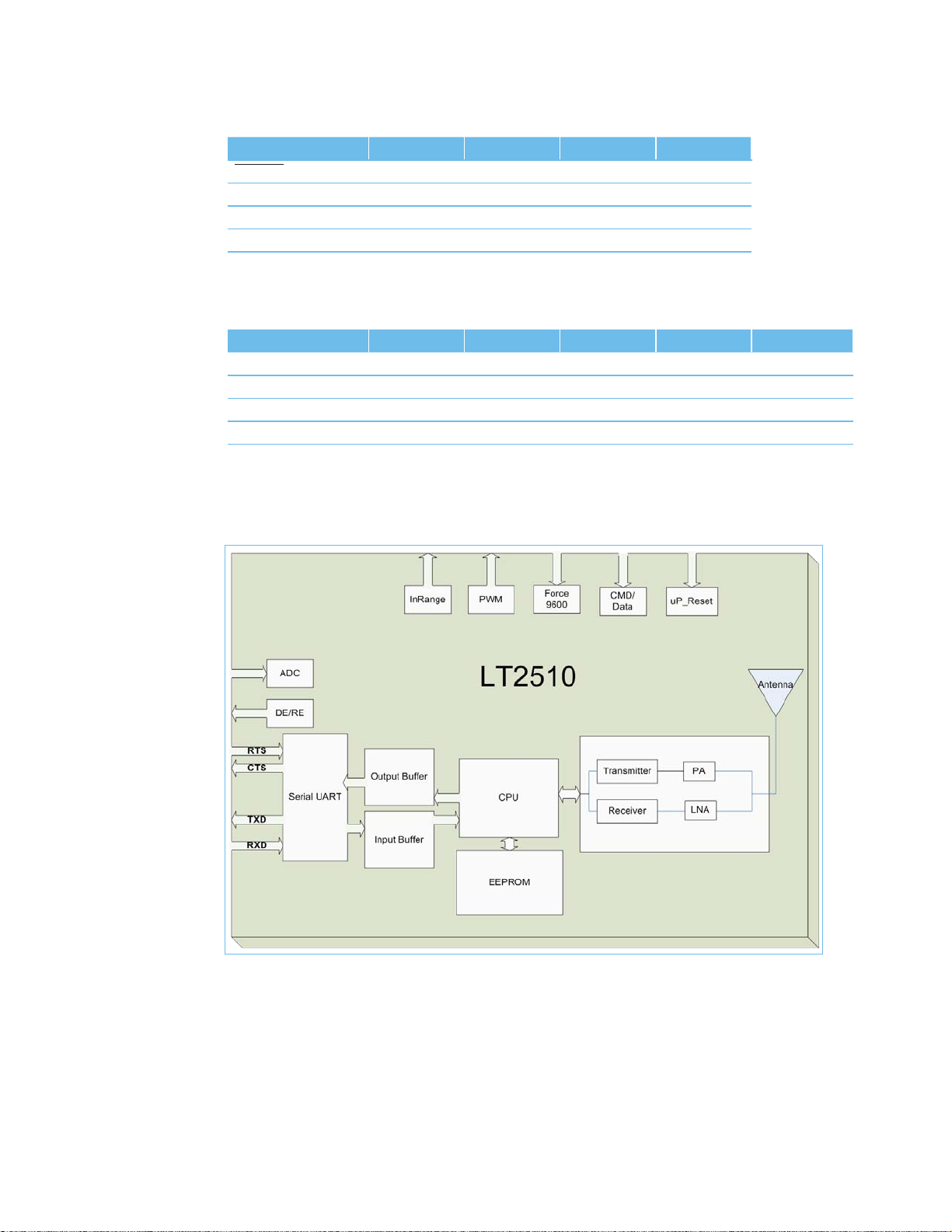
RXD and TXD
The LT2510 accepts 3.3 VDC TTL level asynchronous serial data from the OEM Host via the RXD pin. Data is sent
from the transceiver, at 3.3V levels, to the OEM Host via the TXD pin. Pins should be left oating or high when not in
use. Leaving the RXD tied Low will result in the radio transmitting garbage serial data across the RF.
Force 9600
When pulled logic Low before applying power or resetting, the transceiver’s serial interface is forced to 9600, 8-N-1
(8 data bits, No parity, 1 stop bit): regardless of actual EEPROM setting. The interface timeout is also set to 3 ms and
the RF packet size is set to the default size for the selected RF Data Rate. To exit, the transceiver must be reset or
power-cycled with Test pin logic High or disconnected.
When enabled in the EEPROM, 9600 Boot Option causes the 9600 pin to be ignored on cold boot (power-up),
command boot (0xCC 0xFF) and brown-out conditions. Therefore, the 9600 pin is only observed on warm boots
(reset pin toggled). This can be helpful so that brown-out conditions don’t cause the baud rate to change if the
9600 pin happens to be Low at the time. When 9600 Boot Option is disabled, the 9600 pin will be used for all boot
conditions. 9600 Boot Option is enabled by default.
Force 9600 also is used to wake the radio from sleep. When the pin is taken Low, the radio will wake. The transceiver
will not sleep if the pin is Low when the sleep command is issued.
Note: Because this pin disables some modes of operation, it should not be permanently pulled Low during
normal operation.
μP_RESET
μP_Reset provides a direct connection to the reset pin on the LT2510 microprocessor and is used to force a hard
reset. For a valid reset, reset must be asserted Low for an absolute minimum of 250 ns.
Command/Data
When logic High, the transceiver interprets incoming serial data as transmit data to be sent to other transceivers.
When logic Low, the transceiver interprets incoming serial data as command data. When logic Low, data packets
from the radio will not be transmitted over the RF interface however incoming packets from other radios will still
be received. Enabling CMD/Data RX Disable in the EEPROM will cause incoming RF packets to be queued by the
receiving radio while CMD/Data is Low. When CMD/Data goes High, the data will be sent over the serial interface.
In_Range
The In Range pin will be driven Low when a Client radio’s frequency hopping is synchronized with that of a Server.
In Range will always be driven Low on a server. Following boot, In Range will transition Low in approximately 12ms
on a Server. For a Client the In Range will take an average of 500ms, this time is dependant on the signal strength
of the received beacon, the presence and strength of interference and randomness of the sync function. It can vary
from 150ms to over 1500ms.
GO_0/Hop_Frame
The Hop Frame indicator functionality is disabled by default and controlled by the Control 1, Bit-6 EEPROM Setting.
When enabled this pin will transition logic Low at the start of a hop and transition logic High at the completion of
a hop. The OEM Host is not required to monitor Hop Frame.
RTS Handshaking
With RTS mode disabled, the transceiver will send any received data to the OEM Host as soon as it is received.
However, some OEM Hosts are not able to accept data from the transceiver all of the time. With RTS enabled in
EEPROM, the OEM Host can prevent the transceiver from sending it data by de-asserting RTS (High). Once RTS is
re-asserted (Low), the transceiver will send packets to the OEM Host as they are received.
Note: Leaving RTS de-asserted for too long can cause data loss once the transceiver’s transmit buffer reaches capacity.
CTS Handshaking
If the transceiver buffer lls up and more bytes are sent to it before the buffer can be emptied, data loss will occur.
The transceiver prevents this loss by deasserting CTS High as the buffer lls up and asserting CTS Low as the buffer is
emptied. CTS should be monitored by the Host device and data ow to the radio should be stopped when CTS is High.
DE/RE
When enabled, RS-485 Data Enable, will use the DE/RE pin to control the DE pin on external RS-485 circuitry. When the
transceiver has data to send to the host, it will assert DE/RE High, send the data to the host, and then take DE/RE Low.
PWM Output
PWM ouput can be congured to output on any of three pins (SMT Pins 5, 6 or 7). The PWM Output can optionally
produce a pulse width modulation for RSSI with a period of 315.077uS.