Ohio Lumex RA-915+ User manual


RA-915+ MERCURY ANALYZER
All rights reserved. No part of this publication may be reprinted, recorded or
transferred in any form or by any means, including electronic, mechanical,
photographic, recording, or other, without prior written permission from
OhioLumex Co., Inc.
Neither OhioLumex Co. Inc.,nor its branches shall be liable to the buyer of this
product for damages or losses, which the buyer might suffer as a result of force-
majeure circumstances, abuse of the product, alteration or modification of its
design, which are not provided in the operation and service manuals issued by
OhioLumex Co., Inc.
OhioLumex Co. Inc. shall not be liable for damages or defects, which may arise from
use of additional devices and consumables, which are not mentioned in this
manual.
Information given in this document is subject to change without prior notice.
Distributed by: Air-Met Scientic Pty Ltd
Work with Confidence
Adelaide | Brisbane | Gladstone | Mackay | Melbourne | Perth | Sydney
Air-Met Sales/Service
P: 1800 000 744
F: 1800 000 774
Air-Met Rental
P: 1300 137 067
W: www.airmet.com.au

About this manual
This manual is designed to familiarize you with the principle of operation and
structure of the RA-915+ analyzer (hereinafter referred to as the «analyzer»),
its design, performance characteristics and operating conditions. It contains
information that will provide proper operation and comprehensive utilization of
the analyzer’s capabilities. Please take time to read the manual in order to
attain the best results in operation and to gain the greatest benefit from your
analyzer.
This manual contains:
• List of important safety measures, warnings and precautions, which you
should follow when operating with the analyzer.
• The purpose of the analyzer, its basic performance and analytical char-
acteristics, and operating conditions.
• Brief description of the physical foundations and the principle of opera-
tion of the analyzer, and of its design.
• Functional controls of the analyzer, their purpose and operation.
• Procedures for preparation of the analyzer for operation in different con-
figurations using appropriate operation modes.
• Procedures for handling the analyzer in all of the operation modes using
the display and control unit.
• Brief description of procedures for analyzer operation using a PC.
• Procedures for analyzer maintenance.
• Reference data for correction of results obtained during operation in dif-
ferent modes, as well as instructions for troubleshooting.
i

Safety guidelines
Important safety precautions
Read these rules completely before starting operation with analyzer.
• Carefully study all the sections of this operation manual, analyzer de-
sign and control functions.
• To avoid electrical shock, never work with the analyzer covers taken off.
• Charge the battery on a timely basis. Store the unit with the battery fully
charged.
• Do not put extraneous objects inside the analyzer through its ports.
• Do not allow the ingress of liquids on the case or inside the analyzer.
• Use only the power supply which is provided.
• Never use a defective power supply cable, do not put any objects on the
power supply cable, and locate it in a manner to avoid a trip hazard.
• Do not try to repair the analyzer or adjust its optical units and electronic
boards by yourself, except for cases stipulated in troubleshooting sec-
tion (Appendix 1).
• Call an authorized agent or certified service engineer in the following
cases:
• If the analyzer does not operate properly or its parameters have
noticeably deteriorated.
• If the analyzer has fallen down or if its case is damaged.
• If a liquid has gotten inside the analyzer.
• If you hear unusual sounds or sense unusual smell coming from
the analyzer.
• Keep the analyzer at a minimum distance of 1 meter from heating de-
vices and heat sources. Do not transport analyzer in the trunk of your
car.
• Do not forget to switch the analyzer off when the working day is over and
to disconnect the power supply unit from the mains if the analyzer is not
used for more than 6 hours.
• Never work without absorption and dust filters.
• The analyzer should be switched off before any maintenance operations.
• When measuring mercury concentration, it is necessary to follow in-
structions and documents stating safety regulations for operation in chemi-
cal laboratories and safety rules for operation with electric appliances.
ii

• Observe the following rules during any transportation of the device, as
well as when performing measurements from a moving vehicle (car, heli-
copter, etc.):
• To avoid strong vibration effects, do not place the device on a hard
surface (baggage compartment, floor of a vehicle, etc.).
• Place the device on shock-insulated surfaces (a seat, damping
support, etc.).
• Secure the device on a working surface to prevent its fall or inci-
dental contact with other objects.
• Observe the following safety precautions during outdoor operation:
• Do not work in rainy or foggy weather and avoid precipitation in-
gress inside the analyzer.
• Do not work in dusty ambient air.
Operating personnel should participate in training at OhioLumex Co., Inc. premises
or at a regional service center.
Note symbols
Cautions. Pay attention to these in order to avoid damage of equip-
ment.
Notes. They contain useful information, which will make the opera-
tion with the device easier.
iii

User`s manual RA-915+
Contents
Introduction ....................................................................................................... 2
Application ........................................................................................................ 4
Design and operation of the analyzer .............................................................. 6
Physical foundation and principle of operation ...................................... 6
Design of analyzer ................................................................................. 7
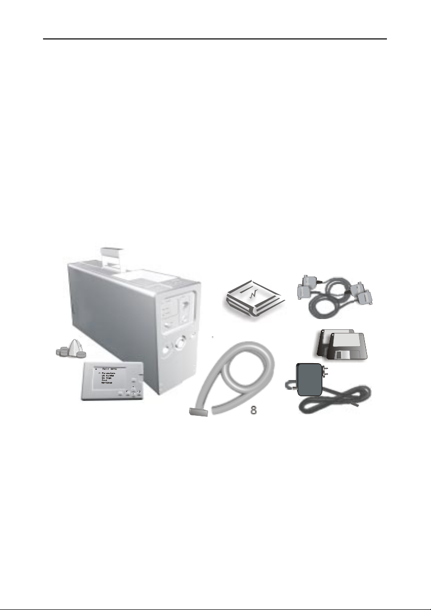
Appearance and functional controls ................................................................. 8
Front panel view ..................................................................................... 8
Back panel view ................................................................................... 10
Right panel view .................................................................................... 11
Left panel view ....................................................................................... 11
Upper panel view .................................................................................. 12
Pre-operational procedures ............................................................................ 12
Operation with the display unit ....................................................................... 15
Description of the MAIN MENU ........................................................... 15
SETTINGS ................................................................................. 15
TEST .......................................................................................... 17
ON STREAM ............................................................................. 19
ON-TIME .................................................................................... 21
HIGH CONCENTRATIONS ........................................................ 24
Operation with a PC ....................................................................................... 24
Serviceability check-up ........................................................................ 25
Measuring procedure ........................................................................... 25
Maintenance ................................................................................................... 25
Charging the battery ............................................................................ 26
Changing of the dust filter .................................................................... 26
Changing of the absorption filter .......................................................... 26
Changing the Pre-filter ......................................................................... 27
Preventive maintenance ....................................................................... 27
Appendix 1 ...................................................................................................... 28
Troubleshooting .................................................................................... 28
Appendix 2 ...................................................................................................... 29
Values of the test number Sk as a function of the temperature of the
test cell ................................................................................................ 29

User`s manual RA-915+
Introduction
Our compliments on the acquisition of the RA-915+ mercury analyzer.
The advanced technologies implemented in the analyzer's production ensure
their extraordinary reliability. The RA-915+ mercury analyzer provides high se-
lectivity of analysis, wide dynamic measurement range, ultra-low mercury de-
tection limits for water and air and, in most cases, enables determination of
mercury content in samples with a complex composition without preliminary
sample preparation. It can be used in the field and in a laboratory as a stand-
alone unit and as part of a computerized analytical system.
The RA-915+ mercury analyzer is a sophisticated high-precision device,
therefore, it should be handled in compliance with operation conditions at all
times to ensure its reliable operation.
2

User`s manual RA-915+
3
2
1
Ent
Esc
5
7,9
8
10
4
3
After taking the device out of the package, make sure that you have
everything necessary for its operation. The complete delivery set includes the
following items:
1 Base unit 1 pc.
2 Display and control unit 1 pc.
3 Power supply unit (for operation from an a.c. mains) 1 pc.
4 Operation manual 1 pc.
5 Kit of spare parts and accessories
(absorption and dust filters) 1 pc. each
6 Canvas shoulder bag (not pictured) 1 pc.
7 Display-unit-connection cable 1 pc.
8 Air intake hose with pre-filter 1 pc.
9 Analyzer-PC interface cable (RS-232 standard) 1 pc.
10 Software for RA-915+ (4 disks) 1 pc.
Options:
• RP-91C attachment for determination of mercury content in solid sam-
ples.
• RP-91 attachment for determination of mercury content in liquid sam-
ples.
• Cable for connection with an external d.c. power supply .
• Cable for analog signal input from a peripheral device.

User`s manual RA-915+
Application
The RA-915+ analyzer (base unit) is intended for measuring mercury
vapor concentration in ambient air and in the air of residential quarters and
production areas, as well as in natural gas and in factory smokestack emis-
sions.
The analyzer can be used for on stream measuring of mercury vapor
concentration in the air both in a stationary mode and in continouous mode
from vehicles (car, helicopter, boat).
The analyzer is used for tackling environmental problems, oil and ore
deposit prospecting, technological processes monitoring, and for industrial sani-
tary and scientific research.
The RA-915+ analyzer is a part of a mercury analytical system, which
enables determination of mercury content in gas, liquid, and solid samples.
The analytical system consists of the RA-915+ analyzer itself, the RP-91 at-
tachment for determination of mercury content in aqueous solutions using the
''cold vapor'' technique, and the RP-91C attachment for measuring mercury con-
centration in liquid and solid samples with a complex composition using the
pyrolysis technique. Basic analytical characteristics of the system are given in
the table below:
Subject Detection
limit
Sample
parameters (flow
rate, volume,
weight)
Detection
technique
Complete
set
Ambient air 2 ng/m320 l/min
Direct RA-915+
Natural and industrial gases 2 - 500 ng/m31 - 20 l/min
Water 0.5 ng/l 20 ml "Cold vapor"
technique
RA-915+
RP-91
Urine 5 ng/l 1 ml
Solid samples (soils, rocks) 0.5 mg/kg 0.2 g
Pyrolysis
technique
RP-91C
RA-915+
Biological samples
(tissues, liver, etc.) 5 mg/kg 0.02 g
Hair 20 mg/kg 0.01 g
Oil and oil products 50 mg/kg 0.01 g
Plants 2 mg/kg 0.05g
Foodstuff 2 - 10 mg/kg 0.005 - 0.05 g
4

User`s manual RA-915+
Detection limit for mercury vapor concentration in air (ng/m3), with the
use of:
Multi-path cell 2
Single-path cell * 500
Maximum mercury vapor concentration under analysis (ng/m3), with the
use of:
Multi-path cell 20 000
Single-path cell * 200 000
(*) in the “High concentration” mode
Accuracy, % ± 20
Main technical data and specifications
Built-it battery 6.3 V
External direct current source 10 – 14 V
A.C. power source, through
external unit 220/110 V, 50/60 Hz
Power consumption 20 W
Dimensions (mm) 460 * 210 * 110
Weight (kg) 7.5
Operating conditions
Ambient air temperature from +1 to 40 0C
Atmospheric pressure 84.0 – 106.7 kPa
Relative humidity under 95 %, at 35 0C
5

User`s manual RA-915+
Design and operation of the analyzer
Physical foundation and principle of operation
The RA-915+ analyzer operation is based on differential Zeeman atomic
absorption spectrometry using high frequency modulation of light polarization (
ZAAS-HFM ).
A radiation source (mercury lamp) is placed in permanent magnetic field
H. The mercury resonance line l=254 nm is split into three polarized Zeeman
components (p, s-and s+, respectively). When radiation propagates along the
direction of the magnetic field, a photodetector detects only the radiation of the
s- components, one of those falling within the absorption line profile and an-
other one lying outside. When mercury vapor is absent in the analytical cell,
the radiation intensities of both s-components are equal. When absorbing at-
oms appear in the cell, the difference between the intensities of the s- compo-
nents increase as the mercury vapor concentration grows.
The s-components are separated by the polarization modulator. The
spectral shift of the s-components is significantly smaller than the widths of
molecular absorption bands and scattering spectra, hence the background ab-
σ-
σ+
H
σ-
σ
-
σ
-
σ+
σ
+
σ
+
π
σ
-σ+
σ
+σ
-
σ
+σ
-
Mercury lamp
Zeeman mercury
triplet
Polarization
modulator
Multi-path cell
Absorption line
envelope
Photodetector
6

User`s manual RA-915+
sorption by interfering components does not affect analyzer’s readings. A multi-
path cell with an effective length about 10 m is used to enhance the sensitivity
of analysis.
Design of analyzer
Block diagram of the analyzer:
1) mercury EDL lamp
2) high-frequency generator
3) polarization modulator
4) modulator control unit
5) multi-path cell
6) photodetector
7) electronic signal-processing unit
8) built-in microprocessor
9) display and control unit
10) gas flow commutation unit
11) absorption filter
12) air pump of the multi-path cell
13) single-path cell or external cell (is part of the RP-91C attachment)
14) air pump of the single-path cell
1
2
35
6
13
7
8
9
4
10
12
13
11
Air
Air Air
Air
14
7

User`s manual RA-915+
Mercury EDL lamp (1), which is placed in the gap between the poles of a
magnet, is excited by high frequency generator (2). The light successively passes
through polarization modulator (3), which is controlled by unit (4), multi-path
cell (5), single-path cell (13) and is detected by photodetector (6). A signal from
the photodetector then arrives at electronic signal-processing unit (7), where
the signal is separated at the modulation frequency and the analytical signal is
formed. After analog-to-digital conversion the signals come to a built-in micro-
processor (8) for the final data processing.
The analyzer can be alternatively controlled as follows:
• From the display and control unit mounted in the base unit of the
analyzer.
• From the display and control unit connected with the base unit via
a signal cable.
• By means of an IBM-compatible computer connected with the
base unit via an interface cable.
Appearance and functional controls
Front panel view
Inlet 2
Absorption filter
Lamp ignition
button
Battery
condition
indicators Power button
Power supply
cable connector
Outlet
Inlet 1 with a dust
filter
8

User`s manual RA-915+
Inlet 1
The analyzer takes air into a multi-path cell with a built-in dust filter.
Inlet 1 (with the dust filter) is used for determination of the mercury
vapor content in the air (or gas)
Inlet 2
This inlet is intended for the air intake into the multi-path cell through the
built-in absorption filter.
Inlet 2 (with the absorption filter) is used only for baseline
measurement.
Absorption filter
The absorption filter excludes mercury from the air/gas being analyzed.
Lamp ignition button
The button ignites the spectral lamp.
Battery condition indicators
CHARGED (green) - the battery charge indicator (does not glow during
operation with the built-in battery). When the battery is being charged,
the indicator flashes at a constant frequency. Duration of flashing indi-
cates level of charge.
DISCHARGED (red) - the battery discharge indicator (does not glow dur-
ing operation with an external power supply source). Duration of flashing
indicates level of discharge.
Power button
The button switches on the analyzer.
Power supply cable connector
It is intended for connection of the power supply cable for operation with
an a.c. transformer.
Outlet
The air duct outlet of the multi-path cell.
9

User`s manual RA-915+
I
II
III
Back panel view
Optical bridge switch
It is used for changing the position of the optical bridge. Light passes
through different analytical cells when the switch is set in different posi-
tions:
Position I - through an external cell (pyrolysis).
Position II - through an accessory single-path cell (auxilary compart-
ment).
Position III - through a built-in multi-path cell.
Position I is used only with the mounted optical unit of the RP-91C
attachment.
Auxilary compartment
This is intended for the single-path analytical cell during operation with
the RP-91 attachment, as well as for analyses of air, natural, or techno-
logical gases in the HIGH CONCENTRATION mode.
Optical bridge
switch
Auxilary
compartment
Retainer
10

User`s manual RA-915+
Retainer
The retention screw is intended for mounting the optical unit of the RP-
91C pyrolytic attachment.
Right panel view
Opening for a pyrolytic attachment
It is used for mounting an optical unit during operation with the RP-91C
attachment.
Left panel view
TEST
handle
Opening for a
pyrolytic
attachment
11

User`s manual RA-915+
TEST handle
The TEST handle is intended for placing a test cell in the optical path to
check the serviceability of the device:
ON position - the test cell is placed into the light beam.
OFF position - the test cell is removed from the light beam.
Upper panel view
Connector
It is intended for connection of the display unit or a PC.
Pre-operational procedures
1 Prior to starting operation, make an external examination of the analyzer
to be sure that there is no physical damage. Do not switch on the analyzer
on your own if your analyzer has a physical damage. Call your regional
dealer for replacement or repair of the analyzer.
2 Place the analyzer on a work-
ing surface so that the display
unit is on top.
3 Select the operating mode
(self-contained operation with
the display unit or operation
with a stand-alone PC). If the
self-contained operation is cho-
sen, install the display and
control unit directly in the base
unit (Fig. A) or connect it to the
base unit with a cable, which
is supplied with the analyzer
(Fig .B).
Connector
Fig.A
12

User`s manual RA-915+
Ent
Esc
Ent
Esc
To operate with a stand-alone PC, it is necessary to connect the analyzer
to the PC by the RS-232 cable, which is included into the basic package*.
To connect the analyzer, do the following:
• Disconnect the analyzer from the a.c. power supply
• Switch off the PC.
• Insert the plug of the connecting cable into the socket of the inter-
face connector on the upper panel of the analyzer.
• Insert the other end of the cable into a socket of the free COM-port
of the PC and secure it.
• If your PC is not equipped with a 9-pin port, it is necessary to use
a special adapter (not included).
* When operating the analyzer as part of a computer system and when
using additional devices (an autosampler, pressure transducers, etc.),
which are connected to a PC, it is necessary to use a double cable, which
is supplied upon request.
Fig. B
13

User`s manual RA-915+
4 Select power supply mode of the analyzer. If the built-in battery is cho-
sen as a power supply, you can directly proceed to the preparation for
measurements, because the analyzer is supplied with a fully charged
battery. If you intend to operate using the transformer, do the following:
• Plug the low-voltage power adapter into the power supply cable
connector on the front panel of the analyzer.
• Use a grounded connection with the appropriate voltage.
5 Prepare your analyzer for measurements. Set the handle of the test cell
on the left panel into the OFF position and the optical bridge handle on
the back panel to position III.
6 Switch the analyzer on with the power button located on the front panel.
Fig. C
14

User`s manual RA-915+
Operation with the display unit
1 Upon switching on the analyzer, the manufacturer's trademark will ap-
pear on the screen of the display and control unit.
2 Press the Ent button on the display and control unit. The MAIN MENU
will be displayed and the sign * (asterisk) will appear in the upper left
corner.
3Рress and hold for several seconds the LAMP IGNITION button on the
front panel of the device. When the spectral lamp turns on, the sign *
(asterisk) will go out.
4 Let the analyzer warm up for at least 20 minutes. Then the device is
ready for measurement.
The presence of the sign * (asterisk) indicates that the spectral lamp
is not glowing or that the lamp radiation intensity is low for
measurements.
Description of the MAIN MENU
SETTINGS
The SETTINGS command is intended for setting the operation parameters.
1 Using the cursor control buttons select the SETTINGS command on the
display unit and press the Ent button. The Settings window will appear.
Display
Asterisk
Enter
Cancel
Buttons for
the cursor
control
15
Table of contents