Page 5 of 127004-00062-A Rev --.indd 8/12/09
Mode d’emploi
Convertisseur de mesure pour tension alternative DVT-XXX(C, CX5, E, E2)
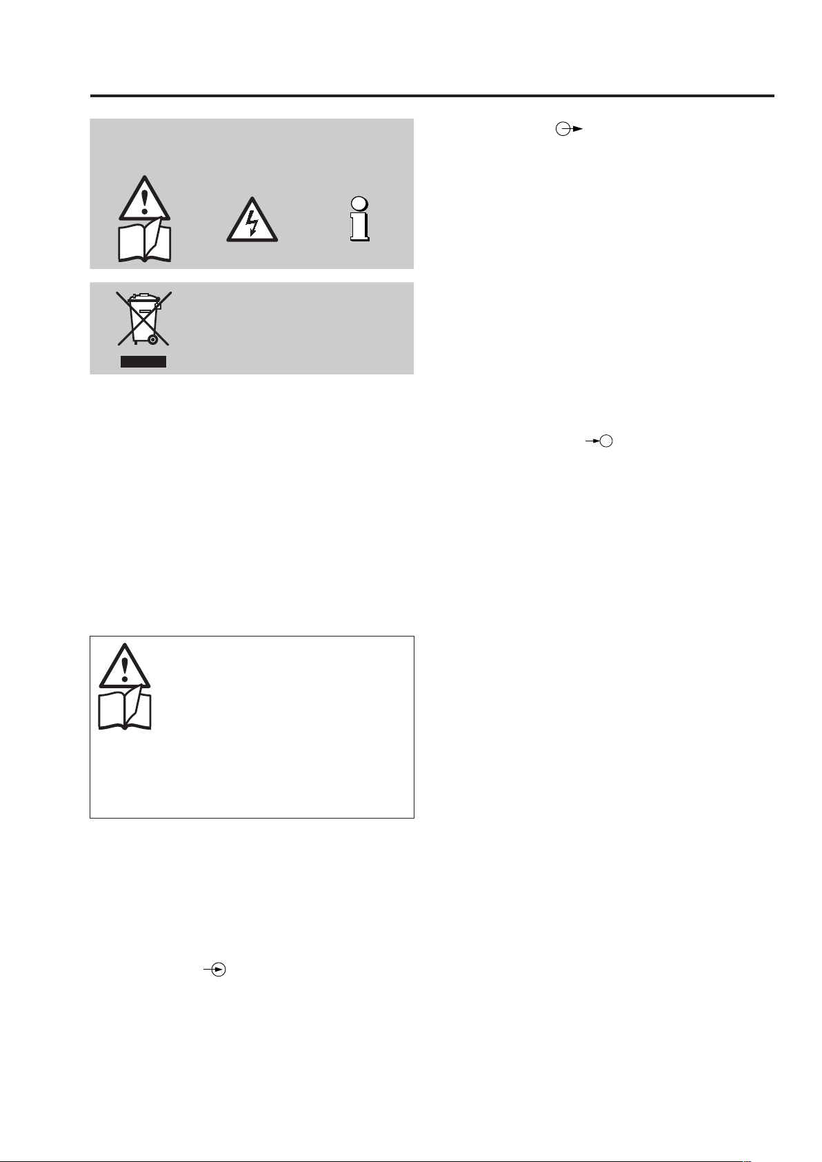
Les conseils de sécurité qui doivent impérativement être
observés sont marqués des symboles ci-contre dans le
présent mode d’emploi:
Les appareils ne peuvent être
éliminés que de façon appropriée!
Sommaire
1. A lire en premier, ensuite ............................................. 5
2. Description brève ........................................................5
3. Caractéristiques techniques........................................5
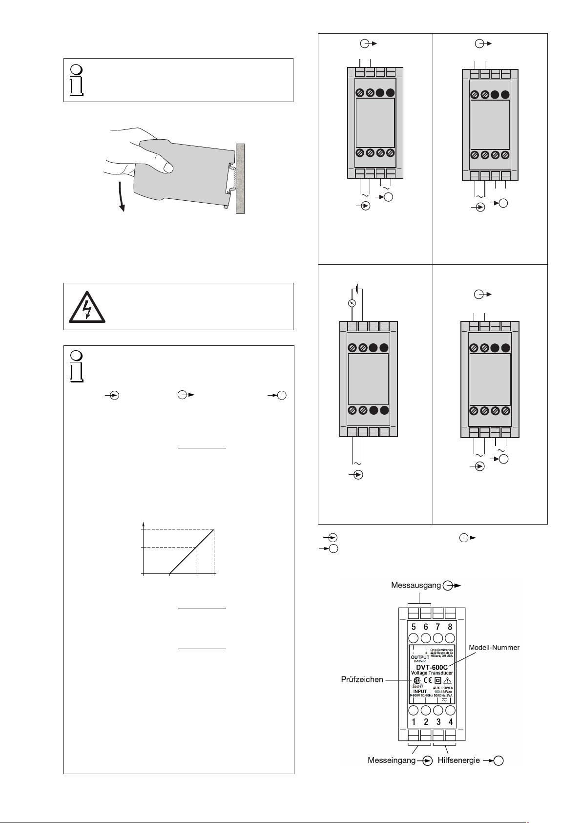
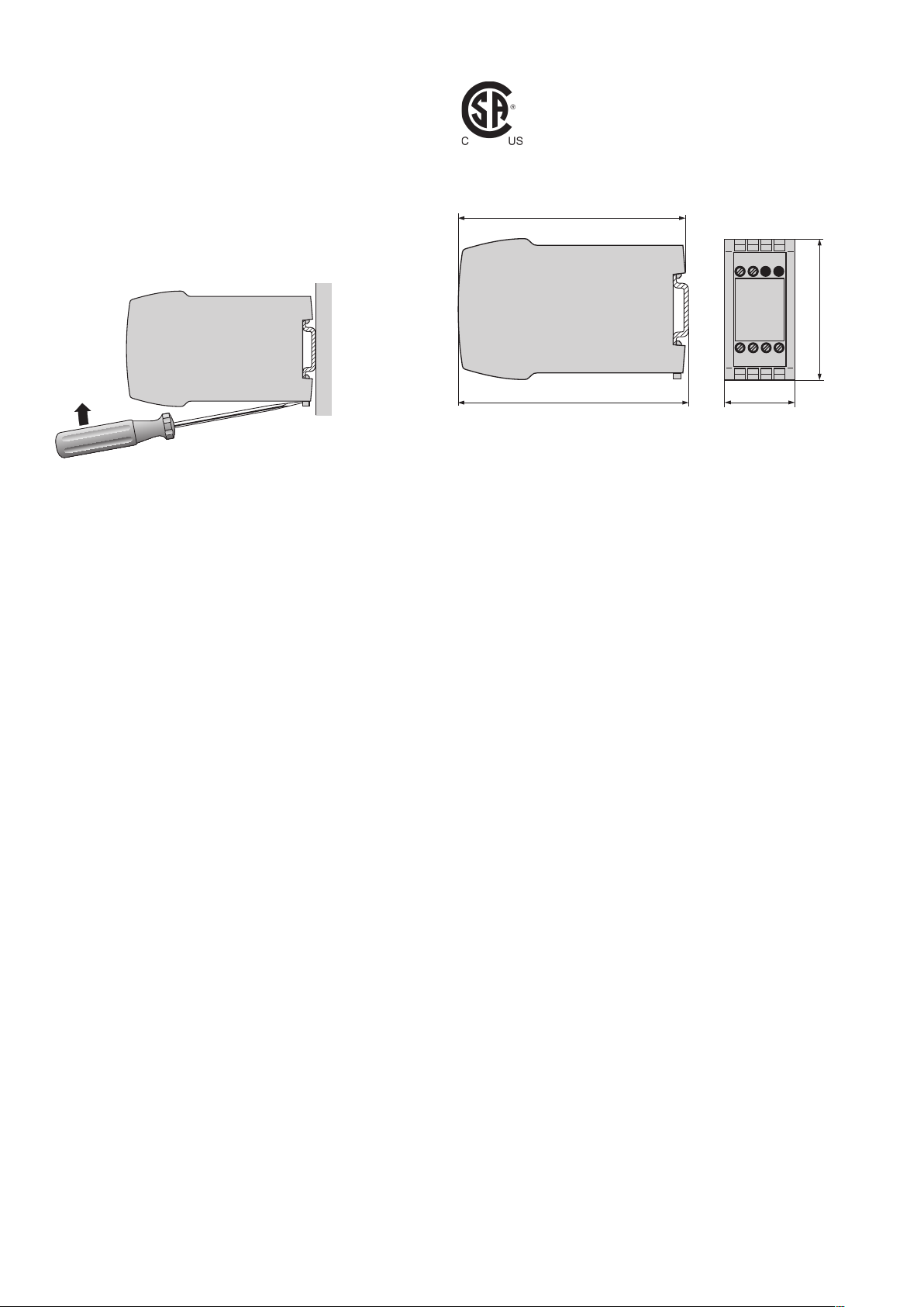
4. Fixation........................................................................6
5. Raccordements électriques.........................................6
6. Mise en service et entretien.........................................7
7. Indication pour le démontage .....................................7
8. Admission d’appareils.................................................7
9. Croquis d’encombrement............................................7
10. Certificats de conformité........................................... 11
1. A lire en premier, ensuite …
Pourunfonctionnementsûretsansdanger,il
estessentielde lirele présentmoded’emploi
et de respecter les recommandations de
sécurité mentionnées dans les rubriques
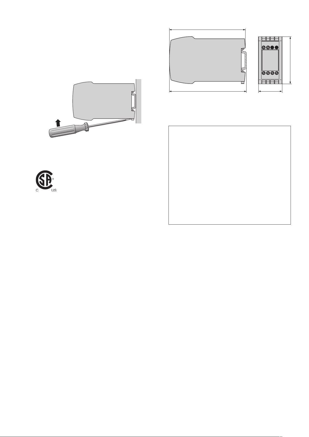
4. Fixation
5. Raccordements électriques.
Ces appareils devraient uniquement être manipulés par
des personnes qui les connaissent et qui sont autorisées
à travailler sur des installations techniques du réglage.
Toute intervention dans l’appareil entraîne l’extinction de
la clause de garantie.
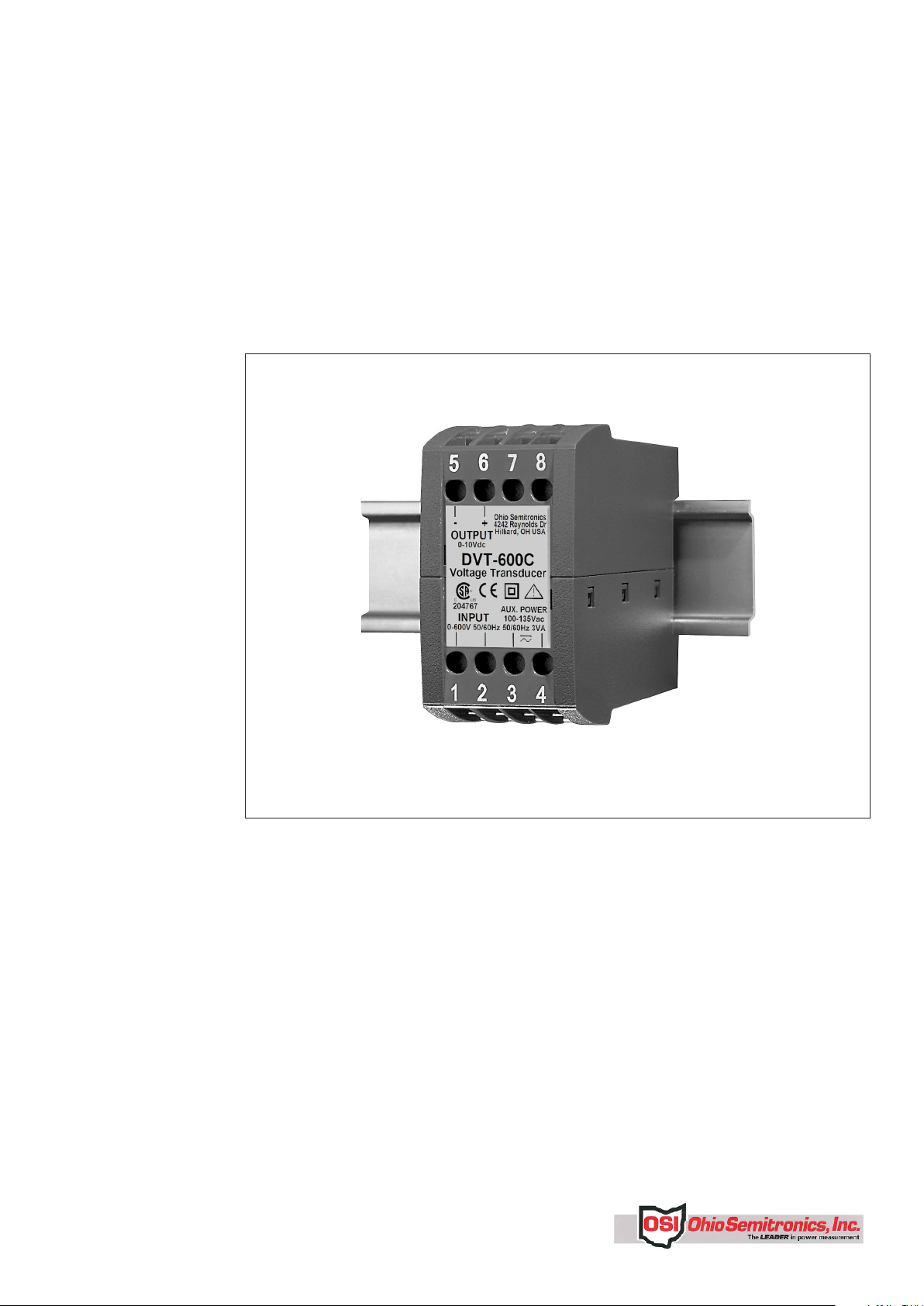
2. Description brève
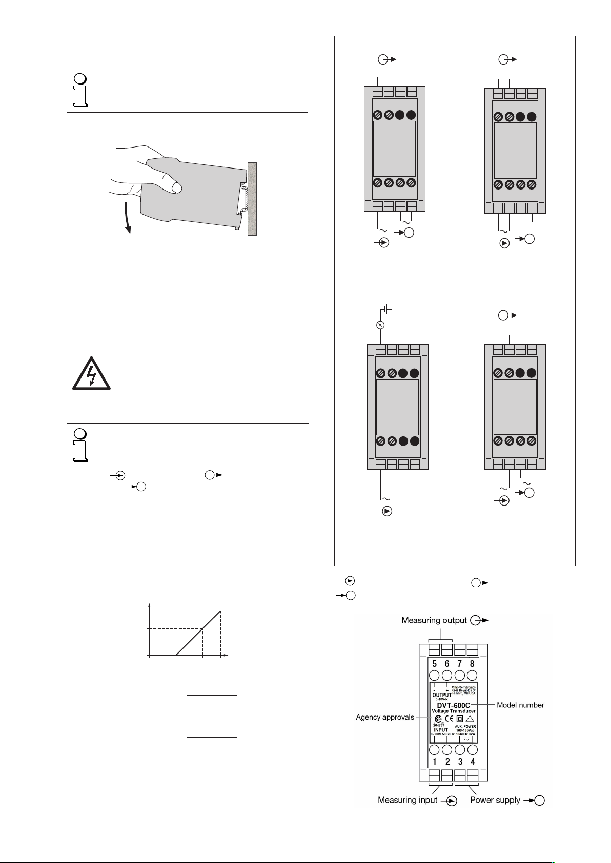
LeconvertisseurdemesureDVT-XXXXtransformeunetension
alternative sinusoïdale en un courant continu ou une tension
continue proportionnel.
3. Caractéristiques techniques
Entrée de mesure
Fréquence nominale: 50/60 Hz
Tension nominale
d’entrée: 0 – 50 à 0 – 600 V
Consommation propre: < UN· 50 µA à UN≤ 150 V
< UN· 20 µA à UN> 150 V,
≤ 400 V
< UN· 5 µA à UN> 400 V
Sortie de mesure
Courant continu: 0 - 1 à 0 - 20 mA resp. live-zéro
0,2 - 1 à 4 - 20 mA
Tension de charge: 15 V
Résistance extérieure: Voir paragraphe«5.Raccordements
électriques»
Pour raccordement
en technique 2 fils: Alimentation à travers le circuit de
sortie 4 - 20 mA, résistance extéri-
eure voir paragraphe «5. Raccorde-
ments électriques»
Tension continue
contrainte: 0 - 1 à 0 - 10 V resp. live-zéro
0,2 - 1 à 2 - 10 V
Résistance extérieure: Voir paragraphe«5.Raccordements
électriques»
Temps de réponse: < 300 ms
Alimentation auxiliaire
Tension alternative
(CA): 24, 110, 115, 120, 230 ou 400 V
± 15%, 50 / 60 Hz
Consommation env. 3 VA,
voir Fig. 2
Options
Tension continue (CC): 24 V, – 15 / + 33 %,
consommation env. 1,5 W,
voir Fig. 3
En technique 2 fils et sortie
4-20 mA, (alimentation à travers le
circuit de sortie) 24 V, – 50/+ 33%,
consommation 1,5 W, voir Fig. 4
Tension continue (CC)
ou tension alternative
(CA): Bloc d’alimentation CC, CA
(CC ou 40 - 400 Hz)
85 - 230 V CC/CA ou
24 - 60 V CC/CA
CC – 15/+ 33%, CA ± 15%
Consommation
≤ 1,5 W resp. ≤ 3 VA, voir Fig. 5
Précision (selon analogie avec EN 60 688)
Valeur conventionnelle: Valeur finale de sortie de mesure
Précision: Classe 0,5
Sécurité
Degré d’encrassement: 2
Catégorie de
surtension: III (à ≤ 300 V)
II (à > 300 V)
Conditions de référence
Température de
fonctionnement: – 10 à + 55 °C
Temp. de stockage: – 40 à + 70 °C
Humidité relative en
moyenne annuelle: ≤ 75 %
Altitude: 2000 m max.
Utiliser seulement dans les intérieurs!