Ohio Steel 100D User manual

READ AND FOLLOW ALL SAFETY RULES AND OPERATING
INSTRUCTIONS BEFORE USING THIS EQUIPMENT
100D
36” DROP SPREADER
6003964 - REV B5/17

18LW
27
23
22
21
26 17
2018N
TOOLS SUGGESTED FOR ASSEMBLY
7/16" wrench and/or socket
large blade screwdriver
pair o pliers
SAFETY INSTRUCTIONS
cordless drill
19LN
19
To stop spreading, return the lever to the closed position.
It is important to clean the spreader a ter each use.
Keep all oreign objects out o the hopper.
Avoid sudden turns or maneuvers.
MAINTENANCE & STORAGE
OPERATION
Operate up and down slopes, never across the ace o slopes.
Never exceed load capacity o 100 pounds.
Never stand, sit or carry passengers on hopper.
Store inside a clean, dry area when not in use.
Oil lever at the pivot screw. Oil wheel bearings.
Periodically check all nuts and bolts or tightness.
Set the adjustment lever to the "close" position.
Re er to the materials application chart with the product
you are using or adjustment setting.
Set adjustment stop to recommended setting by loosening
knob and moving to correct position and tightening knob.
18
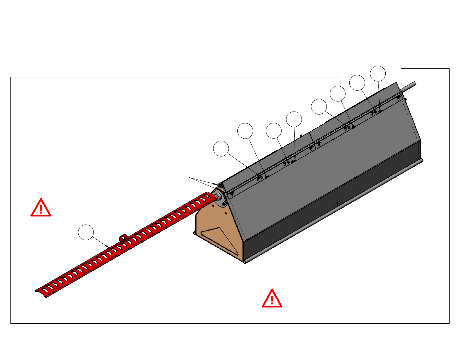
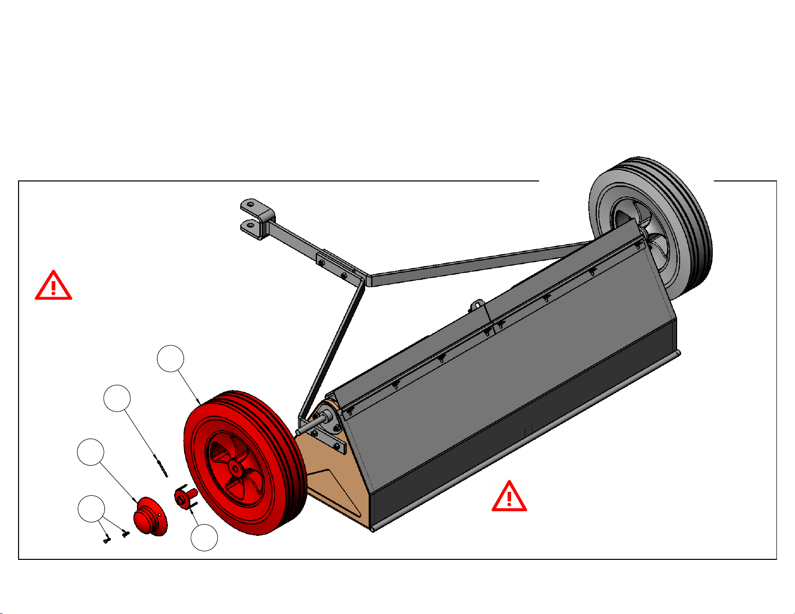
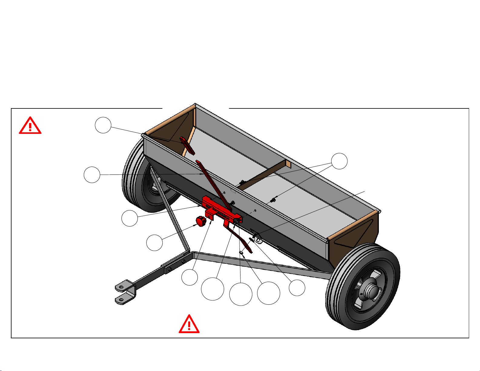
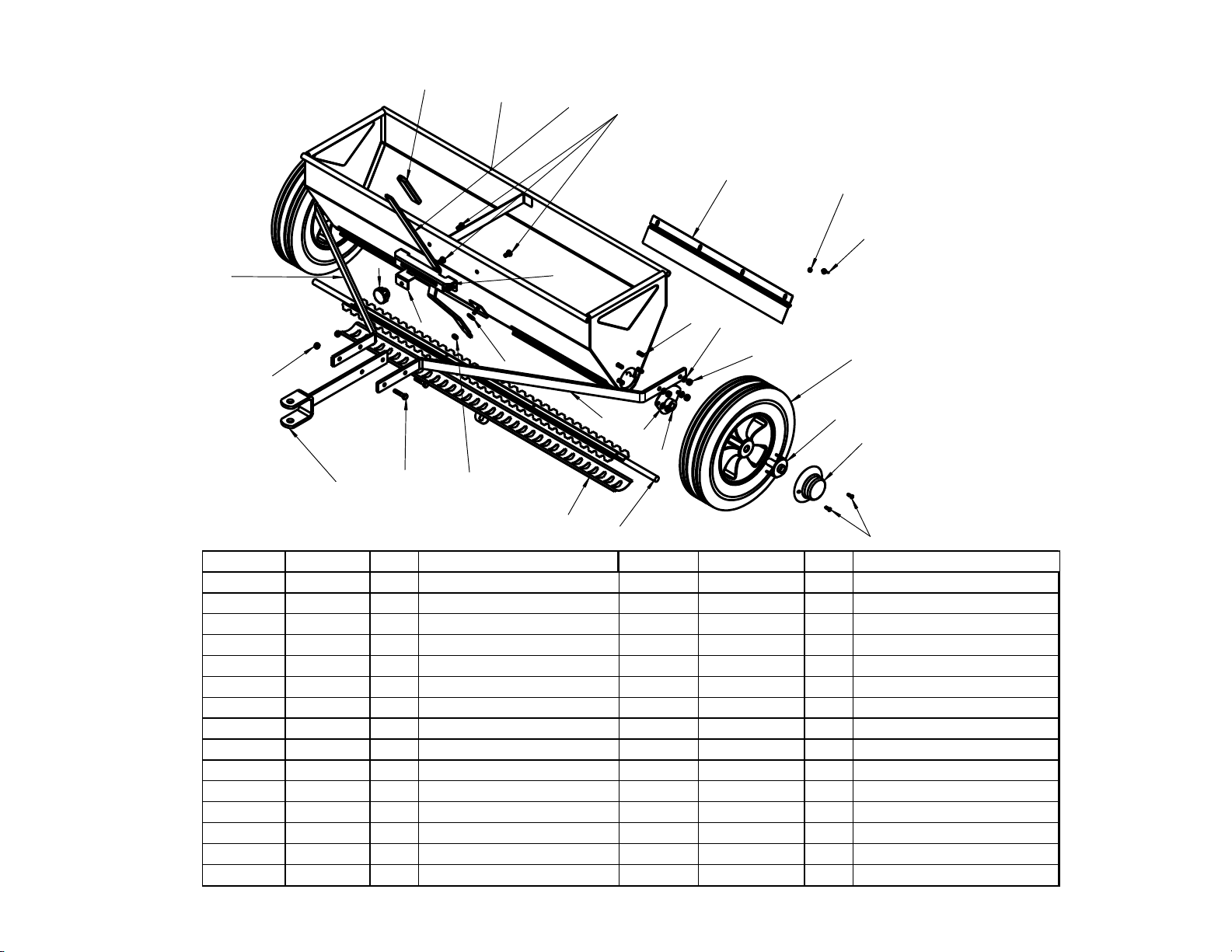
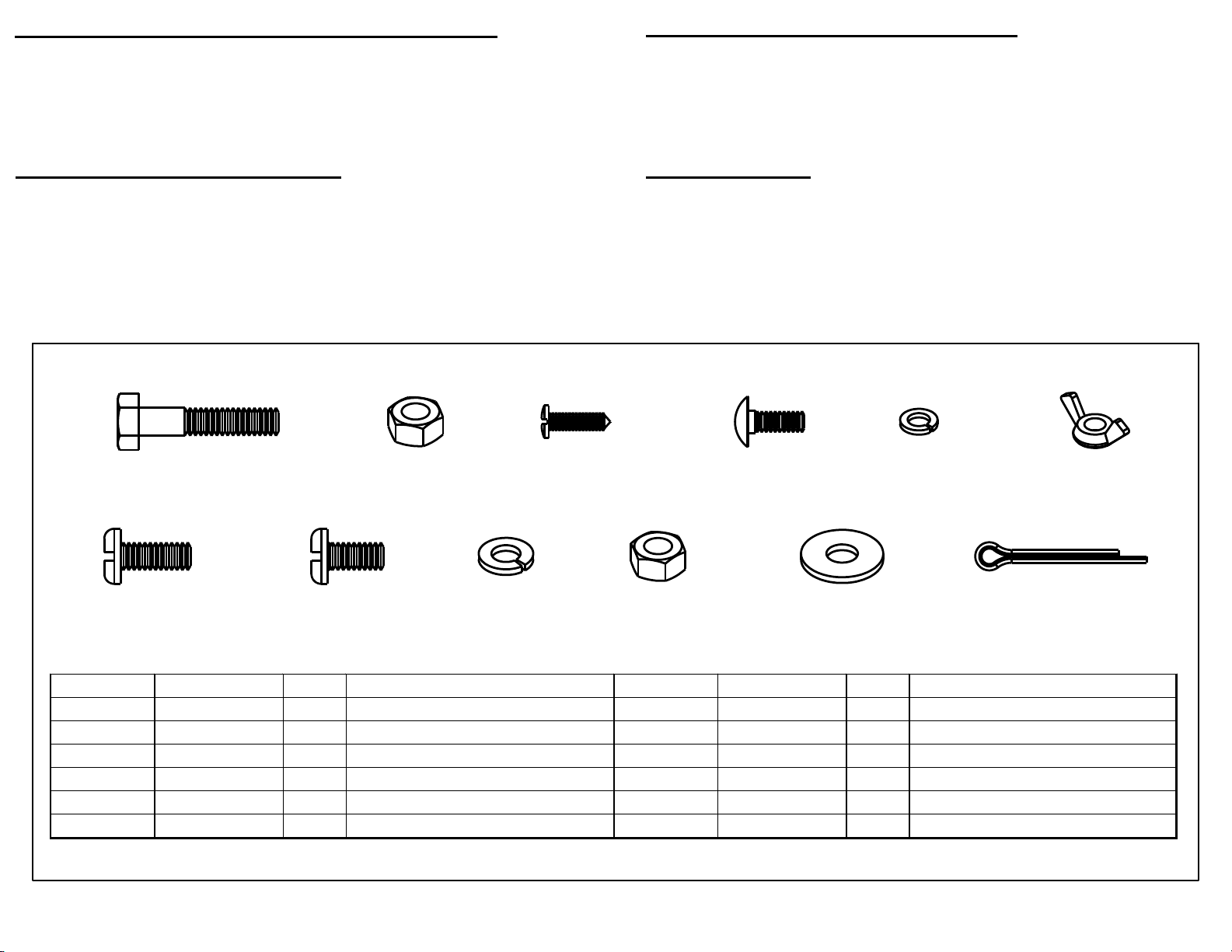
Bolt Bag Contents - 610.241942
FOR MISSING PARTS, Call 1-800-652-2321, Monday - Friday, 8 a.m. - 5 p.m. E.S.T.
Page 2.
REF. NO. PART NO. AMT. DESCRIPTION REF. NO. PART NO. AMT. DESCRIPTION
17 STD541610 8 10-24 wing nut 20 STD551025 1 1/4" lat washer
18 94-18 4 bolt 1/4" x 5/8" pan 21 94-21 3 bolt 1/4" x 1/2" pan
18LW STD551125 6 1/4" lock washer 22 94-22 4 #8 sel tapping screw
18N STD541025 6 1/4" hex nut 23 94-23 2 1/8" x 1" cotter pin
19 STD522512 2 bolt 1/4" x 1 1/4" hex 26 94-26 8 10-24 x 1/2" carriage bolt
19LN STD541425 3 1/4" lock nut 27 STD551110 8 3/16" lock washer

15
12
3
7
8
9
10
11
12
13 14
16
Carton Contents - 610.241942
FOR MISSING PARTS, Call 1-800-652-2321, Monday - F iday, 8 a.m. - 5 p.m. E.S.T.
Page 3.
REF. NO. PART NO. AMT. DESCRIPTION REF. NO. PART NO. AMT. DESCRIPTION
1 94-1 1 hoppe assembly 12 94-12 1 adjustment stop
2 94-2 1 gate 13 94-13 1 adjustment knob
3 94-3 2 scatte plate 14 94-14 2 wheel
7 94-7 2 side plate 15 94-15 1 d ive wheel hub
8 94-8 1 hitch assembly 16 94-16 2 hub cap
9 94-9 1 adjustment leve 24 94-24 1 assembly manual
10 94-10 1 plastic g ip BB 94-BB 1 bolt bag
11 94-11 1 calib ation b acket

Step 1. Take hopper assembly out of carton and remove wheels.
Step 2. Remove parts box, open and verify all parts before beginning to
assemble unit. See pages 2 & 3).
Out of Carton
FOR MISSING PARTS, Call 1-800-652-2321, Monday - Friday, 8 a.m. - 5 p.m. E.S.T.
Page 4.

NOTE: BOLTS ARE TO BE INSERTED
THROUGH INSIDE OF HOPPER ASSEMBLY.
lock washer 27) and wing nut 17).
Step 4. Turn unit over and repeat step 3.
Step 3. Attach scatter plate 3) to hopper assembly 1) by standing
unit upright and inserting carriage bolt 26) through inside of
hopper at each end of scatter plate. Secure "LOOSELY" with
NOTE: POSITION OF
SCATTER PLATE 3).
Add Scatter Plates
FOR MISSING PARTS, Call 1-800-652-2321, Monday - Friday, 8 a.m. - 5 p.m. E.S.T.
Page 5.
27
26
26
3
1
17
17
27

THROUGH INSIDE OF HOPPER ASSEMBLY.
Step 6. Slide gate (2 into grooves of the welded gate retainers and scatter plates (3 , gate can only be inserted as shown.
Step7. Tighten wing nuts at this time.
Step 5. Loosely add the remaining carriage bolts (26 , lock washers (27 and wing nuts (17 in the scatter plates (3 .
NOTE: BOLTS ARE TO BE INSERTED
NOTE: LOCATION OF GATE.
Add Gate
FOR MISSING PARTS, Call 1-800-652-2321, Monday - Friday, 8 a.m. - 5 p.m. E.S.T.
Page 6.
2
17
17
17
17
27
27
27
27
Install gate into grooves

7
18LW
8
19LN
18
19 7
1
18N
THRU INSIDE OF HOPPER.
NOTE: BOLT IS INSERTED
Step 9. Attach hitch asse bly (8) with bolts (19) and lock nuts (19LN).
Step 8. Attach side bars (7) with bolts (18), lock washers (18LW) and nuts (18N), IN DIRECTION SHOWN.
MAKE SURE HITCH IS
INSTALLED TOWARDS
THE FRONT OF UNIT
AS SHOWN.
Add Side Bars and Hitch
FOR MISSING PARTS, Call 1-800-652-2321, Monday - Friday, 8 a. . - 5 p. . E.S.T.
Page 7.

Add Wheels
FOR MISSING PARTS, Call 1-800-652-2321, Monday - Friday, 8 a. . - 5 p. . E.S.T.
Page 8.
16
14
23
15
22
Step 10. Slide wheel (14) on the axle.
Step 11. Add drive wheel hub (15) with legs engaging the the hub of the wheel. Line hole in extruded part of the hub with
ONLY ONE DRIVE WHEEL HUB (15)
IS USED FOR ASSEMBLY.
Step 12. Add hub cap (16) with the two self tapping screws (22).
the hole in the axle and slip cotter pin (23) through these holes and bend to lock in place.
NOTE: IF SCREWS FOR HUB CAP
ARE HARD TO START, DRILL WITH
1/8" BIT OR TAP A NAIL IN ABOUT
A 1/4" TO CREATE A STARTER HOLE.

the adjustment knob (13).
ADJUST LOCK NUT SO THAT
L V R IS ABL TO MOV FR LY.
Step 15. Attach this assembly to the hopper, caging the lever (9). Use two bolts (21) with lock washer and nuts.
Step 16. Add plastic grip (10) to lever (9).
Step 13. Add flat washer (20) over pivot screw, next add the adjustment lever (9) through square hole in tab on the gate
(2) and over pivot screw, secure with lock nut (19LN). NOT : DO NOT OV R TIGHT N, L V R MUST B ABL TO
MOV FR LY.
Step 14. Assemble the adjustment stop (12) to the calibration bracket (11) using bolt (21) through both pieces and into
A LITTL SOAPY WAT R
WILL H LP GRIP SLID
ONTO TH L V R.
Control Assembly
FOR MISSING PARTS, Call 1-800-652-2321, Monday - Friday, 8 a.m. - 5 p.m. .S.T.
Page 9.
20
13
12
11
19LN
18N
9
10
21
18LN
PIVOT SCR W

Repair Parts List - 610.241942
FOR MISSING PARTS, Call 1-800-652-2321, Monday - Friday, 8 a. . - 5 p. . E.S.T.
Page 10.
7
20
22
1
2
3
4
5
6
19LN
7
8
9
10
11
12
13
14
15
16
17
18
27
18LW
18N
19
19LN
21
REF. NO. PART NO. AMT. DESCRIPTION REF. NO. PART NO. AMT. DESCRIPTION
1 94-1 1 hopper asse bly 16 94-16 2 hub cap
2 94-2 1 gate 17 STD541610 8 10-24 wing nut
3 94-3 2 scatter plate 18 94-18 4 bolt 1/4 x 5/8 pan head
4 94-4 1 axle-agitator asse bly 18LW STD551125 6 lock washer 1/4"
5 94-5 2 bearing bracket 18N STD541025 6 hex nut 1/4"
6 94-6 2 nylon bearing 19 STD522512 2 bolt 1/4" x 1 1/4" hex
7 94-7 2 side bar 19LN STD541425 3 lock nut 1/4"
8 94-8 1 hitch asse bly 20 STD551025 1 flat washer 1/4"
9 94-9 1 adjust ent lever 21 94-21 3 bolt 1/4" x 3/4" round
10 94-10 1 plastic grip 22 94-22 4 #8 self thread screw
11 94-11 1 calibration bracket 23 94-23 2 cotter pin 1/8" x 1"
12 94-12 1 adjust ent stop 24 94-24 1 asse bly anual
13 94-13 1 adjust ent knob 25 94-25 1 application chart
14 94-14 2 wheel 26 94-26 8 carriage bolt 1/2"
15 94-15 1 drive wheel hub 27 STD551110 8 3/16" lock washer
Table of contents
Other Ohio Steel Spreader manuals