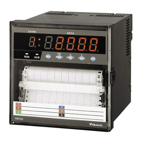
Ohkura VM7000A User manual

VM7000A
YXP627B0104
June 2016 (Second edition)
Copyright © 2009-2016 Ohkura Electric Co., Ltd. All Rights Reserved.
Wideograficzne rejestratory temperatury i procesu VM7000A
http://acse.pl
Wprowadzanie opisów i komentarzy do rejestrowanego procesu
BEZPAPIEROWE REJESTRATORY TEMPERATURY I PROCESU

1
11
1
To use this equipment safely
Thank you for purchasing our VM7000A Paperless Recorder.
Manufacturer
:
Ohkura Electric Co.,Ltd.
Model number
:
It is recorded in marking plate on the main body.
Serial number
:
It is recorded in marking plate on the main body.
Country of manufacture
:
Japan
Note
:
Windows are registered trademarks of Microsoft Corporation.
・
Please installs it, operates it and prepares it, after this manual is often read, and it understands enough.
There is danger where the accident and the trouble occur when handling is mistaken.
・
This specification of Recorder is subject to change without prior notice for product improvement.
・
It is prohibited to remodeling this Paperless Recorder without our permission.
It doesn't assume the responsibility about the accident caused by having remodeled it without our permission.
・
Please keep this manual if you actually use the Recorder.
・
After reading this manual, keep it carefully by the instrument.
・
Please consider this manual to be sure to extend to the final user.
・
Don't use this product in any method not specification by manufacturer. The protective features of this
product may be impaired if it is used in a method not specified in the operation manual.
・
It is prohibited to copy this manual without our permission.
・
This instruction manual is subject to change without prior notice.
[Note]

2
22
2
The symbols below are used on this instrument for the cautioning information.
Be sure to observe the following warnings/cautions and those provided in the text in
order to secure safety in handling the instrument.
WARNING
●
In order to prevent electric shock; be to disconnect this instrument from the main
power source when wiring it.
●
When the effect on the system is expected by the error occurs due to external
factors or failure the instruments, take precautions to ensure the overall safety of
your system.
●
Take precautions to so that an alien substance does not get into the instruments
aperture.
●
In case of damage or failure, contacting serviceman of our company, instruments
should be against unintended operation.
●
In order to prevent an electric shock; be sure to provide protective grounding prior to
turning on this instrument.
●
Do not cut a protective grounding conductor or disconnect protective grounding.
●
Make
sure that the supply voltage for this instrument conforms to the voltage of
the supply source.
Rated power voltage range
:
100-240VAC
Working supply voltage range
:
85-264VAC
Rated power frequency
:
50/60Hz
Power consumption
:
25VA max
Power module that is used in the instruments conform to
EN60950
-
1/A12: 2011.
●
P
lease use in an environment that is shown in the following.
Installation features
:
Indoor
Altitude
:
2000m or less
Ambient temperature
:
0-50
℃
Ambient humidity
:
20-80
%
RH(Non condensing)
Overvoltage category
:
Category
Ⅱ
Allowable pollution degree
:
Pollution degree 2
Vibration
:
10
~
60Hz 0.2m/s2
Impact
:
The impact is not allowed.
●
Do not operate this instrument in the environment where it is exposed to a
combustible / explosive / corrosive gas or water / steam.
●
Do not use in an environment where there is strong Electromagnetic wave.
May cause the operation to become unstable.
●
Provide input and output wiring after turning off the power.
Symbols used on the instrument
This shows “Caution for handling”.
This symbol is used on the parts need to reference the instruction manual for saving human
body and the instrument.
This shows “Protective grounding”.
Be sure to provide protective grounding prior to operate this instrument.
This shows “Risk of electric shock”.
This symbol is used on the parts, which has a risk of electric shock.
CAUTION
General
Protective
Grounding
Power Source
Working
Environment
Input and
Output

3
33
3
●
Do not use empty terminals for other purposes such as relaying, etc.
●
Please confirm the direction to the insertion of SD card.
When forcibly inserting it in a wrong direction, SD card and the terminal on the
main body side might be destroyed.
Please mote that the damage of the equipment by the reverse-insertion becomes off
the subject of amends.
●
Do not replace the main unit or printed circuit boards. When this is neglected, we
cannot guarantee functioning of the instrument. Contact our dealer where you
purchased the instrument, or our sales representative.
[
[[
[Note]
]]
]
●
Deliver this instruction manual to an end user.
●
Prior to handling this instrument, be sure to read this manual.
●
If you have any questions on this manual or find any errors or omissions in this
manual, contact our sales representative.
●
After reading this manual, keep it carefully by the instrument.
●
When the manual is lost or stained, contact our sales representative.
●
It is prohibited to copy or reproduce this manual without our permission.
●
When installing this instrument, put on a protective gear such as safety shoes, helmet,
etc. for your safety.
●
Do not put your foot on the installed instrument or get on it, because it is dangerous.
●
Only our serviceman or persons authorized by OHKURA are allowed to remove
and take the inner module, the main unit and printed circuit boards apart.
●
Use dry cloth to clean the surface of this instrument.
●
Do not use any organic solvent.
●
Cleaning the instrument after turning off the power.
●
This instruction manual is subject to change without prior notice.
Inside of
Instrument
Instruction
Manual
Installation
Maintenance
Cleaning
Revisions
Input and
Output Wiring
Reverse-insertio
n

4
44
4
<
<<
<CONTENTS>
>>
>
1.
Outline
OutlineOutline
Outline
................................
................................................................
................................................................
................................................................
.......................................................
..............................................
.......................
5
55
5
1.1 Modifications ...............................................................................................................................................5
1.2 Software Versions .......................................................................................................................................6
2.
Description of
Description of Description of
Description of Special Main Unit Functions
Special Main Unit FunctionsSpecial Main Unit Functions
Special Main Unit Functions
................................
................................................................
.....................................................
..........................................
.....................
7
77
7
2.1 Manufacturing information display function ............................................................................................7
2.2 Manufacturing information display setting ..............................................................................................9
2.3 Manufacturing Information Comment Data Registration Function......................................................10
2.4 Manufacturing Information Registration Function (Main Unit Operation)...........................................12
2.5 Manufacturing Information Registration Function (Transmission)......................................................14
2.6 Added message function transmission registration function..............................................................16
3.
Special Data Viewer Functions
Special Data Viewer FunctionsSpecial Data Viewer Functions
Special Data Viewer Functions
................................
................................................................
................................................................
................................................................
................................
17
1717
17
3.1 Trend Display .............................................................................................................................................17

5
55
5
1. Outline
This is the operation manual for the model VM7000A paperless recorder, equipped, in addition to its standard
functions, with the ability to register and display manufacturing information compatible with industry 4.0 standards.
This document explains the differences compared to the standard product. Before using the product, you are advised
to read the standard operation manuals (Main Unit Operation Manual: WXPVM7000A0001, Data Viewer Operation
Manual: WXPVM7000A0101, and Parameter Loader Operation Manual: WXPVM7000A0102) to be fully aware of
the standard specifications.
1.1 Modifications
The revisions and changes described in this document are as follows.
Table 1: Main Unit - Modifications
Item
Function
Outline
Remarks
1 Manufacturing
information display
function
Manufacturing information is displayed on the
real-time trend screen and historical trend
screen.
Number of possible recordings: 8
Character limit: 30
See item
2.1.
2 Manufacturing
information display
setting
Functions
The manufacturing information display may
be turned ON or OFF and the name and
number of each piece of registration
information may be turned ON or OFF.
The title may be set as desired.
Title character limit: 8
See item
2.2.
3 Manufacturing
information comment
data registration
function
The registered manufacturing information is
shown as a comment in the measurement
file.
See item
2.3.
4 Manufacturing
information
registration function
(Main unit)
The manufacturing information is registered
using the keys.
See item
2.4.
5 Manufacturing
information
registration function
(Transmission)
Manufacturing information is registered using
Ethernet or RS-485 Modbus transmission.
See item
2.5.
6 Added message
function transmission
registration function
A function was added to enable registration
with Ethernet or RS-485 Modbus
transmission of the message function
previously registered using the Func key, DIs,
or alerts.
See item
2.6.
Table 2: Data Viewer - Modifications
Item
Function
Outline
Remarks
1 Trend display -
Comment display and
print function
expansion
The maximum number of comment columns
for printing trend data has been changed from
3 to 8.
See item
3.1.

6
66
6
1.2 Software Versions
Versions for these specifications are as follows. Please use these version combinations for the main unit,
parameter loader, and data viewer.
Table 3: Versions
Item
Function
Version
Remarks
1 VM7000A main unit Main V12.01
AI V1.50
Standard
2 Data Viewer Ver12.01
3 Parameter loader Ver1.50 Standard

7
77
7
2. Description of Special Main Unit Functions
2.1 Manufacturing information display function
The following manufacturing information is displayed along the vertical and horizontal trends.
Figure 2.1: Trend Display (Real-time)
(1)Title
Displays the information number and title of each registered piece of manufacturing information.
(2)Registration data
Displays manufacturing data sent via transmission.
(1)Title
(2)Registration Data
(1)Title
(2)Registration Data

8
88
8
It can be displayed as a historical trend, but the current manufacturing information is
shown. Past manufacturing information is not displayed. If a measurement file is loaded,
the manufacturing information is hidden.
[
Note
]
Registration data is not saved when the power supply is turned OFF. Be sure to transmit all
the registration information items each time.
[Caution
]

9
99
9
2.2 Manufacturing information display setting
The manufacturing information display may be set by selecting
MENU -> Parameter -> Others -> Products Display.
Item
Name Setting Default
Description
1 Product display
ON/OFF OFF Turns the display of all
manufacturing information
ON or OFF.
2 Information No.
1 to 8 - Select from 8 types of
registration information.
3 Title ASCII
(8 character Max.)
No.1: Model
No.2: Batch
No.3: Serial
No.4: Operator
No.5: Note1
No.6: Note2
No.7: Note3
No.8: Note4
Set the registration
information title.
4 display ON/OFF ALL:ON Choose to show or hide
registration information

1
11
10
00
0
2.3 Manufacturing Information Comment Data Registration Function
The manufacturing information registered via transmission is recorded as a comment in the record file.
Manufacturing information comment registration function
Comments are recorded in the
"Date Time Title: Registration data"
format.
Comments are registered in the file at the following times.
[REC Start]
For ongoing registrations, the comment is recorded at the time of transmission. A piece of data is registered
every second. Numbers that have not been registered through transmission or whose display has been turned
OFF are not recorded.
[REC Stop]
If data is registered when registration is stopped, data that has begun to be registered or that has not yet been
registered will be registered together.
They are
They areThey are
They are
only registered once in the file. Commands that were registered once will not be
registered in the file again unless they are re-registered via transmission. Even registered
information that does not need to be changed every time, such as operator names, must be
transmitted every time.
[Caution]

1
11
11
11
1
RECORD
STOP
RECORD
Batch:002
Batch:002
Model:VM7000A
Batch:005
Serial:150904002
Model:VM7000A
Batch:005
Serial:150904002
STOP
Model:VM7000A
Batch:001
Serial:150904001
Model:VM7000A
Batch:001
Serial:150904001
Batch:003
Batch:004
Batch:004
[ User operation (for HMI) ]
[Measurement file...Comment]
Time
Figure: Relationship between User Operation
through HMI and File

1
11
12
22
2
2.4 Manufacturing Information Registration Function (Main Unit Operation)
Manufacturing information may be registered from the recorder's main unit as described below.
1) Preparation
Assign the manufacturing information function to the Func key to register.
MENU->Setup->Device/Other->Func key
If the Func key has been set to register manufacturing information, other functions, such
as the caption function and message registration function can no longer be accessed
through the
Func key.
[Note
]

1
11
13
33
3
2) Registration
The registration window can be displayed by pressing the Func key on the trend screen.
Touch the text box to display the keyboard and input the information.
The previously registered value is stored, so if there are no changes it does not need to be input.
(If the power supply is turned OFF, the information in the text box will be cleared.)
If there are a number of items to be registered, proceed to the next window by pressing "Back" or "Next" and
enter the information.
When you are finished entering information, tap "Register" to complete registration.

1
11
14
44
4
2.5 Manufacturing Information Registration Function (Transmission)
The manufacturing information is registered using the Modbus transmission (Ethernet, RS-485). The
registration is carried out from the HMI.
(A sample HMI program is attached separately.)
To transmit the manufacturing information via Modbus, batch transmits the 20-word data to the Holder
Register.
One piece of manufacturing information is transmitted at a time. If 8 types of information are used, it will be
transmitted 8 times.
Use Function Code = 10H (Write Multiple Registers) to transmit.
【
Holding register area map
】
Function code: 10H
Function code (continuous writes): 10H
■Example of master transmission (with a start address of 1b58H and a data count of 20)
Component Data length
Data
TCP
RTU
MBAP header (only for Modbus TCP) 7 - -
Slave address - 1 -
Function code 1 1 10H
Data
Relative start address
(high-order) 1 1 1bH
Relative start address (low-order)
1 1 58H
Write data count (high-order) 1 1 00H
Write data count (low-order) 1 1 14H
Number of data bytes 1 1 28H
Data 00 (high-order) 1 1 00H
Data 00 (low-order) 1 1 00H
Data 01 (high-order) 1 1 31H
Data 01 (low-order) 1 1 32H
Data 02 (high-order) 1 1 33H
Data 02 (low-order) 1 1 34H
...
Data 16 (high-order) 1 1 30H
Data 16 (low-order) 1 1 30H
Data 17 (high-order) 1 1 00H
Data 17 (low-order) 1 1 00H
Data 18 (high-order) 1 1 00H
Data 18 (low-order) 1 1 00H
Data 19 (high-order) 1 1 00H
Data 19 (low-order) 1 1 00H
Error check - 2 CRC (16 bits)
Total number of bytes 53 49

1
11
15
55
5
■Example of slave response (with a start address of 1b58H and a data count of 20)
Component Data length
Data
TCP
RTU
MBAP header (only for Modbus TCP) 7 - -
Slave address - 1 -
Function code 1 1 10H
Data
Relative start address
(high-order) 1 1 1bH
Relative start address (low-order)
1 1 58H
Write data count (high-order) 1 1 00H
Write data count (low-order) 1 1 14H
Error check - 2 CRC (16 bits)
Total number of bytes 12 8
【
Holding Register Area
】
Function code : 10H
Corres
pond
Func.
Code
Address
Relative
Address
(HEX)
Name Description Remarks
0x10
47001 1B58 Product data No. 0000H to 0013H
47002 1B59 Reserve Reserve
47003 1B5A Product data
Strings(1/15)
Characters(1/30)
Characters(2/30)
47004 1B5B Product data
Strings(2/15)
Characters(3/30)
Characters(4/30)
47005 1B5C Product data
Strings(3/15)
Characters(5/30)
Characters(6/30)
47006 1B5D Product data
Strings(4/15)
Characters(7/30)
Characters(8/30)
47007 1B5E Product data
Strings(5/15)
Characters(9/30)
Characters(10/30)
47008 1B5F Product data
Strings(6/15)
Characters(11/30)
Characters(12/30)
47009 1B60 Product data
Strings(7/15)
Characters(13/30)
Characters(14/30)
47010 1B61 Product data
Strings(8/15)
Characters(15/30)
Characters(16/30)
47011 1B62 Product data
Strings(9/15)
Characters(17/30)
Characters(18/30)
47012 1B63 Product data
Strings(10/15)
Characters(19/30)
Characters(20/30)
47013 1B64 Product data
Strings(11/15)
Characters(21/30)
Characters(22/30)
47014 1B65 Product data
Strings(12/15)
Characters(23/30)
Characters(24/30)
47015 1B66 Product data
Strings(13/15)
Characters(25/30)
Characters(26/30)
47016 1B67 Product data
Strings(14/15)
Characters(27/30)
Characters(28/30)
47017 1B68 Product data
Strings(15/15)
Characters(29/30)
Characters(30/30)
47018 1B69 Reserve
47019 1B6A Reserve
47020 1B6B Reserve
Ensure you transmit the manufacturing information by writing 20 words sequentially (Func code = 10H). An
error will occur if they are only partially transmitted.

1
11
16
66
6
2.6 Added message function transmission registration function
Messages usually registered with the keys, DIs, and alerts are recorded via Modbus transmission (Ethernet,
RS-485). The registration is carried out from the HMI.
(A sample HMI program is attached separately.)
To transmit the manufacturing information via Modbus, transmit the 1-word data to the Holder Register.
Use the Function Code = 06H (Write Single Register) to transmit.
【
Holding register area map
】
Function code: 06H
Function code (continuous writes): 06H
■Example of master transmission (with a start address of 006bH and a data count of 1)
Component Data length
Data
TCP
RTU
MBAP header (only for Modbus TCP) 7 - -
Slave address - 1 -
Function code 1 1 06H
Data
Relative start address
(high-order) 1 1 00H
Relative start address (low-order)
1 1 6bH
Data(high-order) 1 1 AAH
Data(low-order) 1 1 01H
Error check - 2 CRC (16 bits)
Total number of bytes 12 8
■Example of slave response (with a start address of 006bH and a data count of 1)
Component Data length
Data
TCP
RTU
MBAP header (only for Modbus TCP) 7 - -
Slave address - 1 -
Function code 1 1 06H
Data
Relative start address
(high-order) 1 1 00H
Relative start address (low-order)
1 1 6bH
Data(high-order) 1 1 AAH
Data(low-order) 1 1 01H
Error check - 2 CRC (16 bits)
Total number of bytes 12 8
【
Holding Register Area
】
Function code : 10H
Corres
pond
Func.
Code
Address
Relative
Address
(HEX)
Name Description Remarks
0x06
40108 006B Message Send
AA01H
to
AA14H

1
11
17
77
7
3. Special Data Viewer Functions
3.1 Trend Display
Open a file registered with manufacturing information display function, and manufacturing information is
registered in the comment display area.

1
11
18
88
8
[Print Function]
To display a comment using the data viewer's print function, set the comment item on the print preview screen
as shown below.
Comment data is shown within the trend.
Comment display
Other manuals for VM7000A
3
Table of contents
Other Ohkura Measuring Instrument manuals
Popular Measuring Instrument manuals by other brands

Emerson
Emerson ControlWave Series Site Considerations for Equipment Installation, Grounding, and Wiring Manual

Apera
Apera 2401-C user manual

Murphy
Murphy ATS series installation instructions

IFM Electronic
IFM Electronic ecomot200 FR-2 operating instructions

Heyuan Intelligence
Heyuan Intelligence DZ81-MA3UI5C user manual

Renishaw
Renishaw PH10 PLUS Series Installation and user guide