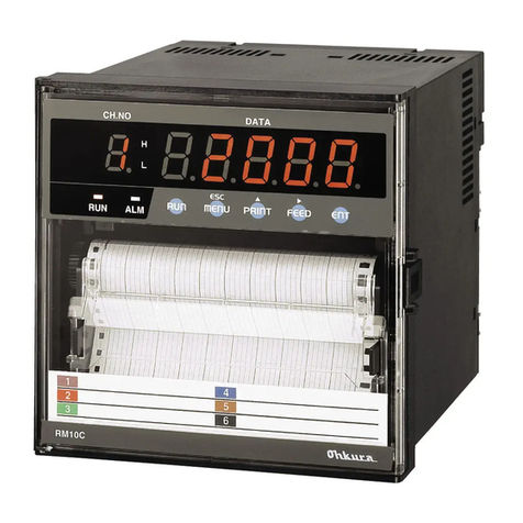
Ohkura RM10C User manual

――HXPRM10mnC0005E
0
RM10C
HYBRID RECORDER
COMMUNICATION COMMAND
INSTRUCTION MANUAL
HXPRM10mnC0005E
Jan. 2016 (2nd Edition)
All Rights Reserved, Copyright © 2004-2016, Ohkura Electric Co., Ltd.

――HXPRM10mnC0005E
1
For safety using
Thank you for purchasing our RM10C Hybrid Recorder.
In order to this instrument to exhibit all of its functions effectively and correctly, read and understand this
instruction manual thoroughly before using the instrument.
The symbols below are used on this instrument for the cautioning information.
Symbols used on the instrument
This shows “Caution for handling”. This symbol is used on the parts need to
reference the instruction manual for saving human body and the instrument.
This shows “Protective grounding”. Be sure to provide protective grounding prior
to operate this instrument.
This shows “Risk of electric shock”. This symbol is used on the parts, which has
a risk of electric shock.
Be sure to observe the following warnings/cautions and those provided in the text
in order to secure safety in handling the instrument.
WARNING
In order to prevent electric shock; be sure to disconnect this instrument from
the main power source when wiring it.
(1) In order to prevent an electric shock; be sure to provide protective
grounding prior to turning on this instrument.
(2) Do not cut a protective grounding conductor or disconnect protective
grounding.
(1) Make sure that the supply voltage for this instrument conforms to the
voltage of the supply source.
(2) Attach a protective cover prior to turning on this instrument.
Do not operate this instrument in the environment where it is exposed to a
combustible/explosive/corrosive gas or water/steam.
Provide input and output wiring after turning off the power.
全般
General
全般
Protective Grounding
全般
Power Source
全般
Working Environment
全般
Input and Output Wiring

――HXPRM10mnC0005E
2
CAUTION
Do not use empty terminals for other purposes such as relaying, etc.
When transporting this instrument or the equipment with this instrument
incorporated in it, take measures to preventopening the door and falling out the
inner module.
Do not touch the switches, etc. inside this instrument. Also, do not replace the
main unit or PRINTed circuit boards. When this is neglected, we cannot
guarantee functioning of the instrument. Contact our dealer where you
purchased the instrument, or our sales representative.
[Note]
(1) Deliver this instruction manual to an end user.
(2) Prior to handling this instrument, be sure to read this manual.
(3) If you have any questions on this manual or find any errors or omissions in
this manual, contact our sales representative.
(4) After reading this manual, keep it carefully by the instrument.
(5) When the manual is lost or stained, contact our sales representative.
(6) It is prohibited to copy or reproduce this manual without our permission.
(1) When installing this instrument, put on a protective gear such as safety
shoes, helmet, etc. for your safety.
(2) Do not put your foot on the installed instrument or get on it, because it is
dangerous.
Only our serviceman or persons authorized by our company are allowed to
remove and take the inner module, the main unit and PRINTed circuit boards
apart.
(1) Dispose the replaced batteries in a correct way.
(2) Do not incinerate plastics of maintenance parts and replacement parts. A
harmful gas may be produced.
(1) Use dry cloth to clean the surface of this instrument.
(2) Do not use any organic solvent.
(3) Cleaning the instrument after turning off the power.
This instruction manual is subject to change without prior notice.
全般
Input and Output Wiring
全般
Transportation
全般
Inside of Instrument
全般
Instruction Manual
全般
Installation
全般
Maintenance
全般
Disposal
全般
Cleaning
全般
Revisions

――HXPRM10mnC0005E
3
Using procedure for this manual
1.Using procedure
This instruction manual consists of “For safety using”, “Contents” and “Chapter 1 to Chapter 6” as bellow.
Read the applying sections for your purpose to use this instrument.
Chapter and TITLE
For purchase
and install
For initial
setting and
change setting
For daily
operation
For using
communication
For
maintenance
and
trouble-shootin
g
For safety using (page 1)
◎
◎
◎
◎
◎
1. INTRODUCTION
◎
◎
Original protocol
2. THE RECEPTION OF
DATA
○
◎
○
3. DATA TRANSMISSION
○
◎
○
4. NOTE OF DATA
COMMUNICATION
○
◎
○
ModbusRTU protocol
5. OVERVIEW
○
◎
○
6. DATA TRANSMISSION
AND RECEPTION
○
◎
○
◎:Be absolutely certain to read this.
○:Be certain to read this if you need.
The symbols below are used on the warning and cautioning information in this manual.
Symbols used on this manual
WARNING
Failure to observe this information could result in death or injury.
Be absolutely certain to read this.
CAUTION
Failure to observe this information could damage the instrument.
Be certain to read it.
[Note]
This is cautionary information for correct use of the instrument.
Be certain to read it.
[Reference]
This is information to help you use the functions of this instrument more
effectively.
2.Guide of Instruction manual
The instruction manuals of this instrument are as the table below.
Name
Part No.
Outline
1
RM10C Hybrid Recorder
instruction manual
HXPRM10mnC0001E
HXPRM10mnC0002E
Explanation for installing, wiring,
standard operation. And setting
or operation for using this
instrument.
2
RM10C Hybrid Recorder
Communication Command
instruction manual
HXPRM10mnC0005E
Explanation for reading and
writing data of the recorder by
communication function.
This
manual

――HXPRM10mnC0005E
4
CONTENTS
1. INTRODUCTION .........................................................................................................................5
1.1 General Description.............................................................................................................5
1.2 Difference in RS-485, RS-232C...........................................................................................5
1.3 Original Protocol - Basic item about the command..............................................................5
1.4 Basic item about the Modbus RTU protocol.........................................................................6
2. ORIGINAL PROTOCOL - THE RECEPTION OF THE DATA .....................................................7
2.1 Setup command...................................................................................................................7
2.1.1 Setup command list..................................................................................................7
2.1.2 Setting of INPUT RANGE/RECORD SPAN..............................................................8
2.1.3 Setting of Alarm......................................................................................................11
2.1.4 Setting of the Unit...................................................................................................11
2.1.5 Setting of the 1st chart speed.................................................................................11
2.1.6 Setting of the date/time...........................................................................................12
2.1.7 Copying the Setting Data of the channel ................................................................12
2.1.8 Setting of the Printing cycle(Multipoint type only)...................................................12
2.1.9 Setting of the Zone Recording...............................................................................12
2.1.10 Setting of the Partial Compression/Expansion........................................................13
2.1.11 Setting of the Digital Print ON/OFF.........................................................................13
2.1.12 Setting of the Tag Character...................................................................................13
2.1.13 Setting of the Comment Character .........................................................................14
2.2 Control command...............................................................................................................15
2.2.1 Control command list..............................................................................................15
2.2.2 Recording Start/Stop ..............................................................................................16
2.2.3 Manual Print Start/Stop...........................................................................................16
2.2.4 List Print Start/Stop.................................................................................................16
2.2.5 Engineering list Print Start/Stop..............................................................................16
2.2.6 Choice of the display contents................................................................................17
2.2.7 Communication comment print out.........................................................................17
3. ORIGINAL PROTOCOL - DATA TRANSMISSION ...................................................................18
3.1 Getting the Set Value.........................................................................................................18
3.2 Data Reception Example...................................................................................................18
4. ORIGINAL PROTOCOL - NOTES OF COMMUNICATION .......................................................19
4.1 Half-Duplex Transmission..................................................................................................19
4.2 Multiple access ..................................................................................................................19
4.3 Continuation of Opening the Link.......................................................................................19
4.4 Outputting the Status.........................................................................................................19
5. MODBUS RTU PROTOCOL - OVERVIEW ...............................................................................20
5.1 Modbus RTU Protocol........................................................................................................20
5.2 Add new items and Map version........................................................................................20
6. MODBUS RTU PROTOCOL - DATA TRANSMISSION AND RECEPTION...............................21
6.1 Communication Protocol....................................................................................................21
6.2 Function codes ..................................................................................................................21
6.3 Error response...................................................................................................................21
6.4 Reading of input register area............................................................................................22
6.4.1 Reading of input register area ................................................................................22
6.4.2 Input Register Area Map.........................................................................................23
6.5 Reading and writing of the holding register area................................................................26
6.5.1 Reading of the holding register area.......................................................................26
6.5.2 Writing of the holding register area (Single)............................................................27
6.5.3 Writing of the holding register area (Continuation) .................................................28
6.5.4 Holding register area map ......................................................................................29
6.5.5 Holding register area setting range detail...............................................................35

――HXPRM10mnC0005E
5
1. INTRODUCTION
1.1 General Description
This instruction manual describes the communication command of the RM10C Recorder. Please refer to the
instruction manual (HXPRM10mnC0001E, HXPRM10mnC0002E) for the transmission of the measurement
data, a setup of communication and wiring.
1.2 Difference in RS-485, RS-232C
There is no difference between RS-232C and RS-485 about the communication command in this Recorder.
But, wiring and signal level are different.
1.3 Original Protocol - Basic item about the command
The communication command consists of a command distinction code, a parameter, delimiter(comma),
and terminator. The format of the command is as follows.
(Example)SR02 VOLT,200mV,0,20000 (terminator)
Command distinction code:
This code is defined by two characters the capital letter. (Exp. SR)
If the command needs a channel number, a channel number is described behind the
distinction code.
Parameter: Each parameter is divided with comma.
All the setting value is shown with the integer. (The plus sign can be omitted.)
The space character in the input parameter is ignored. The other side, the space
character in the unit code, the comment printout code and the tag printout code isn't
ignored. The parameter can be omitted unless the parameter is varied. But, a comma(,)
can't be omitted. Comma which is in front of the terminator can be omitted.
(Example)SR02,VOLT,,,(CR)(LF)
The date parameter, the time parameter and the channel number parameter have fixed
length. When that parameter length is different, these data induce errors.
(1)Date YY/MM/DD (8 characters)
(2)Time HH:MM:SS (8 characters)
(3)Channel Number:CHXX (2characters)
Omission is possible
contents
Wiring and
communication
procedure
Request
measurement
value
Setting of the
recorder
Control of the
recorder
RM10C Hybrid Recorder
instruction manual
(HXPRM10mnC0001E,
HXPRM10mnC0002E)
○
○
RM10C Hybrid Recorder
Communication Command
instruction manual
(HXPRM10mnC0005E)
○
○

――HXPRM10mnC0005E
6
1.4 Basic item about the Modbus RTU protocol
Modbus protocol is a Modicon Inc. (AEG Schneider Automation International SAS) is a communication
protocol that was developed for the PLC, are listed in the protocol specification (PI-MBUS-300 Rev.J).
Please refer to the same specification for the specification of the Modbus protocol.
In this manual, we describe the function code and data content of mainly Modbus protocol that can be used
in the present equipment.

――HXPRM10mnC0005E
7
2. ORIGINAL PROTOCOL - THE RECEPTION OF THE DATA
2.1 Setup command
2.1.1 Setup command list
Table 2.1 Setup command list
Command
Setting item
The number of
the parameters
Contents of a parameter
SR
Setting the range
MAX 7
Channel,Mode,Range(Reference
Channel)
Span lower limit value.
Span higher limit value.
Scaling lower limit value.
Scaling higher limit value
SA
Setting the Alarm
7
Channel,
Alarm level
Alarm on/off
Alarm type,Alarm set point
Relay on/off、Relay No.
SN
Setting the Unit
2
Channel, Unit
SC
Setting
the Chart Speed
1
1st Chart speed
SD
Setting the Date/Time
2
Date, time
SF
Setting
the Digital Print
2
Channel
Digital print on/off
ST
Setting the Tag
2
Channel, Tag characters
SG
Setting the Comment
2
Comment number,
Comment characters
SZ
Setting
the Zone recording
3
Channel, Left position,
Right position
SP
Setting the Partial
Compression/Expansi-
on recording
4
Channel, Partial on/off
Compression
Expansion
SE
Setting
the Chart Speed
1
2nd chart speed
SY
Copying
the Setting data
2
Copy-from channel
Copy-to channel
SS
Setting
the recording cycle
1
Recording Cycle
(Multipoint type only)

――HXPRM10mnC0005E
8
2.1.2 Setting of INPUT RANGE/RECORD SPAN
The input range and record span of each channel is set up as follows.
<Format>
SR(CH),(Mode),(Pr1),(Pr2),(Pr3),(Pr4),(Pr5),(Pr6),(Pr7)(CR)(LF)
CH: Specify the channel number to set.
Mode: The input mode is set up.
PrN: The number of PrNvaries depend on the contents of Mode.
(1) Setting of the record skip.
The record of the channel, which specified with CH is stopped.
(The pen of pen type recorder is fixed on the zero point.)
CH:Setting Channel 01~06(The pen type is 01~02.).
Mode:SKIP
Example)SR05,SKIP(CR)(LF)
The 5th channel doesn't record.
(2) Setting of the Voltage, the Current, the Thermocouple or the RTD input range.
CH:Setting Channel 01~06(The pen type is 01~02.).
Mode:VOLT,TC or RTD
Pr1:Range
Pr2:Left end(Zero Input Value) Refer to table 2.2.
Pr3:Right end(Span Input Value)
Example)SR02,TC,K,0,3000(CR)(LF)
The input of 2nd channel is recorded in Thermocouple type K 0.0-300.0 ℃
(3) The setting of Difference/Sum/Mean operation.
CH:Setting Channel 01~06(The pen type is 01~02.).
Mode:DELT,SIGM or MEAN
Pr1:Refference Channel
・Choose a smaller channel than CH.
・The reference channel must be VOLT, TC, RTD or SCL mode.
Pr2:Left end(Zero Input Value)
Pr3:Right end(Span Input Value)
Example)SR05,02,DELT,0,3000(CR)(LF)
The output of the 5th channel shows a difference between the input of the 5th channel and
the 2nd channel (CH5-CH2). In this case, the input range of 5th channel becomes the
same as 2nd channel.
Refer to table 2.2.

――HXPRM10mnC0005E
9
(4) The setting of Scaling.
CH:Setting Channel 01~06(The pen type is 01~02.).
Mode:SCL
Pr1:VOLT, TC, RTD
Pr2:Scaling Mode
Pr3:Left End(Zero Input Value)
Pr4:Right End(Span Input Value)
Pr5:Scaling Left End
Pr6:Scaling Right End
Pr7: Decimal point position(0~4)
Example)SR04,SCL,RTD,PT,0,3000,0,30000,2(CR)(LF)
[CAUTION]
Pr5 - 7 can be omitted. If you omit the parameters, three parameters must be omitted
simultaneously.
(5) The setting of Square Root
CH:Setting Channel 01~06(The pen type is 01~02.).
Mode:SQRT
Pr1:Range(Only VOLT Input)
Pr2:Left End(Zero Input Value)
Pr3:Right End(Span Input Value)
Pr4:Scaling Left End
Pr5:Scaling Right End
Pr6:Decimal point position(0~4)
Example)SR03,SQRT,mA,400,2000,0,10000,2(CR)(LF)
※Pr5 - 7 can be omitted. If you omit the parameters, three parameters must be omitted
simultaneously.
(6) The setting of Decade
CH:Setting Channel 01~06(A pen type is 01~02.).
Mode:DECAD
Pr1:Range(Only VOLT Input)
Pr2:Left End(Zero Input Value)
Pr3:Right End(Span Input Value)
Pr4:Scaling Left End
Pr5:Scaling Right End
Example)SR01,DECAD,10mV,0,1000,10E+01,10E+06(CR)(LF)
[CAUTION]
Pr5 - 7 can be omitted. If you omit the parameters, three parameters must be omitted
simultaneously.
[CAUTION]
Pr5 - 7 can be omitted. If you omit the parameters, three parameters must be omitted
simultaneously.
Refer to table 2.2.
Refer to table 2.2.
Refer to table 2.2.

――HXPRM10mnC0005E
10
Table 2.2 Setting range
Input
Range
Range or
Scaling
Mode
Zero Input
Value
(Left End)
Span Input
Value
(Right End)
Decimal
Point
(Fixation)
Note
VOLT
10mV
-1000
1000
2
±10mV
20mV
0
2000
2
0~20mV
50mV
0
5000
2
0~50mV
200mV
-2000
2000
1
±200mV
1V
-1000
1000
3
±1V
5V
0
5000
3
0~5V
10V
-10000
10000
2
±10V
mA
400
2000
2
4~20mA
TC
B
0
18200
1
0~1820℃
320
33080
1
32~3308゚F
R
0
17600
1
0~1760℃
320
32000
1
32~3200゚F
S
0
17600
1
0~1760℃
320
32000
1
32~3200゚F
K
-2000
13700
1
-200~1370℃
-3280
24980
1
-328~2498゚F
E
-2000
8000
1
-200~800℃
-3280
14720
1
-328~1472゚F
J
-2000
11000
1
-200~1100℃
-3280
20120
1
-328~2012゚F
T
-2000
4000
1
-200~400℃
-3280
7520
1
-328~752゚F
C
0
23200
1
0~2320℃
320
42080
1
32~4208゚F
Au-Fe
10
3000
1
1~300K
N
0
13000
1
0~1300℃
320
23720
1
32~2372゚F
PR40-20
0
18800
1
0~1880℃
320
34160
1
32~3416゚F
PLII
0
13900
1
0~1390℃
320
25340
1
32~2534゚F
U
-2000
4000
1
-200~400℃
-3280
7520
1
-328~752゚F
L
-2000
9000
1
-200~900℃
-3280
16520
1
-328~1652゚F
RTD
Pt100
-2000
6500
1
-200~650℃
-3280
12020
1
-328~1202゚F
JPt100
-2000
6300
1
-200~630℃
-3280
11660
1
-328~1166゚F
Example)When decimal point position is "1", the input value "1000" is recognized as "100.0".

――HXPRM10mnC0005E
11
2.1.3 Setting of Alarm
The Alarm of each channel is set up as follows.
<Format>
SA(CH),(LEVEL),(ON/OFF),(TYPE),(VALUE),(RLY ON/OFF),(RLY No.)(CR)(LF)
Part of underline can be omitted.
2.1.4 Setting of the Unit
The Unit of each channel is set up as follows.
<Format>
SN(CH),(UNIT)(CR)(LF)
CH:Setting Channel 01~06(The Pen type is 01~02.).
UNIT:The Unit is set up with the code as shown in table 2.3.( Within 6 characters.)
When you use the code beyond 7FHEX, the data length must be used as 8 bit.
Please refer to the chapter 7.2.7 of the instruction manual (HXPRM10mnC0001E,
HXPRM10mnC0002E) for the data length setting.
2.1.5 Setting of the 1st chart speed
The 1st chart speed is set up as follows.
<Format>
SC(CHART SPEED)(CR)(LF)
The chart speed is chosen from the following table.
CHART SPEED (Multipoint type)
CHART SPEED (Pen type)
Item
Contents
Setting Range
Note
CH
Channel number
01~06(multi)
01~02(pen)
LEVEL
Alarm Level
1~4
ON/OFF
Alarm ON/OFF
ON or OFF
It can be omitted.
TYPE
Alarm Type
H:Upper-limit
L:Lower-limit
It can be omitted.
VALUE
Set Value
It can be omitted.
RLY ON/OFF
Relay ON/OFF
ON or OFF
It can be omitted.
RLY No.
Relay No.
I01~I06(multi)
I01~I03(pen)
It can be omitted.
0
1
2
3
4
5
10
15
20
25
30
40
50
60
75
80
90
100
120
150
160
180
200
240
300
360
375
450
600
720
750
900
1200
1500
5
10
15
20
25
30
40
50
60
75
80
90
100
120
150
160
180
200
240
300
360
375
450
600
720
750
900
1200
1500
1800
2400
3000
3600
4500
4800
5400
6000
7200
9000
10800
12000

――HXPRM10mnC0005E
12
2.1.6 Setting of the date/time
The date/time of the internal watch of the recorder is set up as follows.
<Format>
SD(DATE),(TIME)(CR)(LF)
DATE:YY/MM/DD
(YY)Year 00~99
(MM)Month 01~12
(DD)Day 01~31
TIME:HH:MM:SS
(HH)Hour 00~23
(MM)Minute 00~59
(SS)Second 00~59
2.1.7 Copying the Setting Data of the channel
The setup data of the channel can be copied on other channels.
<Format>
SY(CHS),(CHD)(CR)(LF)
CHS:Copy-from Channel 01~05(The Pen type is 01 only.)
CHD:Copy-to Channel ( CHS< CHD)
The copy-to channel must set larger value than copy-from channel.
2.1.8 Setting of the Printing cycle(Multipoint type only)
The Printing cycle of the recorder is set up as follows.
<Format>
SS(PRINTING CYCLE)(CR)(LF)
PRINTING CYCLE: 10,20,30 and 60 (sec)
2.1.9 Setting of the Zone Recording
The Zone Recording of each channel is set up as follows.
<Format>
SZ(CH),(LEFTPOSITION),(RIGHTPOSITION)(CR)(LF)
CH:Setting Channel 01~06(The Pen type is 01~02.).
LEFTPOSITION:0~95%
RIGHTPOSITION:5~100%
Part of underline can be omitted. The original setup is inherited when it omits.

――HXPRM10mnC0005E
13
2.1.10 Setting of the Partial Compression/Expansion
The Partial Compression/Expansion recording of each channel is set up as follows.
<Format>
SP(CH),(ON/OFF),(BOUNDARY POSITION),(BOUNDARY VALUE)(CR)(LF)
CH:Setting Channel 01~06(The Pen type is 01~02.).
ON/OFF:Partial Compression/Expansion function ON or OFF
BOUNDARY POSITION: 1~99%
BOUNDARY VALUE:
CH is VOLT,TC,RTD,DELT,SIGM or MEAN mode: In the span data
CH is SCALE,SQRT,DECAD mode: In the scale data
Part of underline can be omitted. The original setup is inherited when it omits.
2.1.11 Setting of the Digital Print ON/OFF
The Digital Print ON/OFF of each channel is set up as follows.
<Format>
SF(CH),(ON/OFF)(CR)(LF)
CH:Setting Channel 01~06(The Pen type is 01~02.).
ON/OFF:ON or OFF
2.1.12 Setting of the Tag Character
The Tag Character of each channel is set up.
<Format>
ST(CH),(TAG)(CR)(LF)
CH:Setting Channel 01~06(The Pen type is 01~02.).
TAG:The Tag Character is set up with the character code shown by the table 2.3.
( Multipoint type is within 7 characters. Pen type is within 5 characters.)
When you use the character code beyond 7FHEX, the data length of communication
function must be used as 8 bit. Please refer to the chapter 7.2.7 of the instruction manual
(HXPRM10mnC0001E, HXPRM10mnC0002E) for the data length setting.

――HXPRM10mnC0005E
14
2.1.13 Setting of the Comment Character
The Comment Character to print by the Digital Input is set up.
<Format>
SG(Cn),(COMMENT)(CR)(LF)
Cn:Comment Number(1~3)
COMMENT:A Comment Character is set up with the character code shown by the table 2.3.
(Multipoint type is within 16 characters. Pen type is within 12 characters.)
When you use the character code beyond 7FHEX, the data length of communication
function must be used as 8 bit. Please refer to the chapter 7.2.7 of the instruction
manual (HXPRM10mnC0001E, HXPRM10mnC0002E ) for the data length setting.
Character Code Table Table 2.3 Character Code Table
2*
3*
4*
5*
6*
7*
A*
B*
C*
D*
E*
F*
*0
SP
0
@
P
p
0
0
Π
π
*1
!
1
A
Q
a
q
1
1
Α
Ρ
α
ρ
*2
″
2
B
R
b
r
2
2
Β
Σ
β
σ
*3
#
3
C
S
c
s
3
3
Γ
Τ
γ
τ
*4
$
4
D
T
d
t
4
4
Δ
Υ
δ
υ
*5
%
5
E
U
e
u
5
5
Ε
Φ
ε
φ
*6
&
6
F
V
f
v
6
6
Ζ
Χ
ζ
χ
*7
′
7
G
W
g
w
7
7
Η
Ψ
η
ψ
*8
(
8
H
X
h
x
8
8
Θ
Ω
θ
ω
*9
)
9
I
Y
i
y
9
9
Ι
ι
*A
*
:
J
Z
j
z
Κ
κ
*B
+
;
K
[
k
{
+
+
Λ
λ
*C
,
<
L
¥
l
|
±
Μ
μ
*D
-
=
M
]
m
}
Ν
ν
*E
.
>
N
^
n
 ̄
-
-
Ξ
ξ
*F
/
?
O
_
o
o
o
Ο
ο
Example)The character code "43HEX" represents as the character "C".

――HXPRM10mnC0005E
15
2.2 Control command
2.2.1 Control command list
Table 2.4 Control command list
Command
Control Item
The number of
parameter
The explanation of operation
PS0
Recording Start
-
This command is the same as RUN key.
PS1
Recording Stop
-
MP0
Manual Print starting
-
This command is the same as key
operation of "Manual Print".
MP1
Manual Print stop
-
LS0
List Print starting
-
This command is the same as key
operation of "List Print".
LS1
List Print stop
-
SU0
Engineering List Print starting
-
This command is the same as key
operation of "Engineering List Print".
SU1
Engineering List Print stop
-
UD0
Chooses an Auto Display
-
When choosing the manual display,
channel number can be set.
But, the channel number can be omitted.
Exp.)Display the measurement value of
5th channel.
UD
1,05
(CR)(LF)
UD1
Chooses a Manual Display
1
UD2
Chooses a Date Display
-
UD3
Chooses a Time Display
-
UD4
Chooses a Display OFF
-
PR0
Communication comment print
out (Sync printout)
2
The printout of characters which is
received by the communication.
The parameter consist of printout colors
and the printout characters.
PR1
Communication comment print
out (Async printout)
2
BO0
Byte output order
(High byte earlier)
2
This command only affects the binary
mode.
(Please refer to the chapter 8 of the
instruction manual for details.)
(HXPRM10mnC0001E,
HXPRM10mnC0002E)
BO1
Byte output order
(Low byte earlier)
2
TS0
Chooses of the measurement
value output
-
This command chooses send data.
The send data actually uses
LF command, FM command.
(Please refer to the chapter 8 of the
instruction manual for details.)
(HXPRM10mnC0001E,
HXPRM10mnC0002E)
TS1
Chooses of the setting value
output.(Refer to Chapter 3)
-
TS2
Chooses of the decimal point
position and the unit character
output.
-
FM0
The ASCII output of the
measurement data.
2
This command outputs a measure-ment
value. The parameter consists of the
output starting channel and output
ending channel.
(Please refer to the chapter 8 of the
instruction manual for details.)
(HXPRM10mnC0001E,
HXPRM10mnC0002E)
FM1
The Binary output of the
measurement data.
2
LF
The output of the setting value,
the unit character and the
decimal point position.
2
This command outputs a setting value.
The parameter consists of the output
starting channel and output ending
channel.
(Please refer to the chapter 8 of the
instruction manual for details.)
(HXPRM10mnC0001E,
HXPRM10mnC0002E)

――HXPRM10mnC0005E
16
2.2.2 Recording Start/Stop
This command starts or stops recording of the recorder.
<Format>
PS0(CR)(LF) ・・・The recorder starts the record.
PS1(CR)(LF) ・・・The recorder stops the record.
2.2.3 Manual Print Start/Stop
This command starts or stops printing of the "Manual print".
<Format>
MP0(CR)(LF) ・・・The manual print is started.
MP1(CR)(LF) ・・・The manual print is stopped.
2.2.4 List Print Start/Stop
This command starts or stops printing of the "List print".
<Format>
LS0(CR)(LF) ・・・The list print is started.
LS1(CR)(LF) ・・・The list print is stopped.
2.2.5 Engineering list Print Start/Stop
This command starts or stops printing of the "Engineering list print".
<Format>
SU0(CR)(LF) ・・・The Engineering list print is started.
SU1(CR)(LF) ・・・The Engineering list print is stopped.

――HXPRM10mnC0005E
17
2.2.6 Choice of the display contents.
This command chooses the display mode of the recorder.
The Auto Display, the Manual Display, the Date Display, the Time Display and Display OFF can be chosen.
When receiving this command, the display of recorder changes automatically.
<Format>
UD0(CR)(LF) ・・・・・Auto Display
UD1,(CH)(CR)(LF) ・・・・・Manual Display
UD2(CR)(LF) ・・・・・Date Display
UD3(CR)(LF) ・・・・・Time Display
UD4(CR)(LF) ・・・・・Display OFF
CH:The manual display channel 01~06(The Pen type is 01~02.).
The underline part can be omitted.
2.2.7 Communication comment print out
This command prints the character strings, which is received by the communication.
Please refer to table 2.3 for the character code. When you use the character code beyond 7FHEX,
the data length of communication function must be used as 8 bit. Please refer to the chapter 7.2.7
of the instruction manual (HXPRM10mnC0001E, HXPRM10mnC0002E ) for the data length setting.
<Format>
PR0,(COLOR),(TEXT)(CR)(LF) ・・・・・The Sync printout.
PR1,(COLOR),(TEXT)(CR)(LF) ・・・・・The Async printout.
COLOR:Choose a printout color. (The Pen type is only PRP.)
PRP:Purple RED:Red BLK:Black GRN:Green BRN:Brown BLU:Blue
TEXT:Maximum character number of Multipoint type is 47.
Maximum character number of Pen type is 21.

――HXPRM10mnC0005E
18
3. ORIGINAL PROTOCOL - DATA TRANSMISSION
3.1 Getting the Set Value
When the recorder receives "(TS1)+(ESC T)+(LF)", the recorder sends the setting value continuously
according to the following table 3.1.
The output formats of each command are as same as that of format when it set up.
Table 3.1 Order of the set value transmission
Order
Command
Description
1
PS
Recording/Stop
2
SR
Input range, recording span
3
SN
Unit
4
SA
Alarm
5
SC
1st chart speed
6
SS
Analog printing period
7
SZ
Zone recording
8
SP
Partial compression/expansion recording
9
SF
Digital printing
10
ST
Tag character
11
SG
Comment character
12
SE
2nd chart speed
13
UD
Display indication mode
14
EN
End
3.2 Data Reception Example
Send the set value in this order
Open command
Open the link
Set value data output
designation
command(TS1)
Prepares for
the set value
data output
Data update
command(ESC T)
Prepares for
the update
data
Data output request
command(LF)
Sends the
update data
Close command
Close the link
Send the command to the
recorder to which you want to
start data transmission.
When you want to get the set
value from same recorder
continuously, this is
unnecessary.
Send the command to the
recorder each time.
Send the command when you
want to send to other recorder.

――HXPRM10mnC0005E
19
4. ORIGINAL PROTOCOL - NOTES OF COMMUNICATION
4.1 Half-Duplex Transmission
The recorder side is the half-duplex transmission. The recorder cannot receive the data while sending
the data. When the host computer sends the next data, all the receiving data must be completed.
4.2 Multiple access
Don't open another recorder when one recorder is opened on the same line.
4.3 Continuation of Opening the Link
Don't take interval for a long time, after sending the open command.
The syntax error may occur when not sending data some time.
Be sure to send the close command "ESC C" when you do not use the communication.
If the syntax error occurs, send the status output command "ESC S" to reset the error.
(※The close command cannot reset the syntax error.)
4.4 Outputting the Status
When the open-link recorder has a data error on its link, the recorder saves the error in the internal status
area as a communication error. The "ESC S" command can reads this status.
Issuing this command clears the on-going error. Refer to chapter 8.5 in the instruction manual.
(HXPRM10mnC0001E, HXPRM10mnC0002E)
Be sure to reset the error when data set to recorder. When no error reset, you may not be able to judge
command, which the error specify.
Other manuals for RM10C
1
Table of contents
Other Ohkura Measuring Instrument manuals