RLS Wacon SYCON 2702 User manual

Operating manual
SYCON 2702
Analyzer for automated monitoring
of total hardness, residual hardness or carbonate hardness in process water

© RLS Wacon GmbH ∙ +49 (0)5121 28126 0 ∙ i[email protected] 2
General notes......................................................................................................................................................................... 4
Safety instructions and used symbols .................................................................................................................... 4
Transport............................................................................................................................................................................ 5
Storage ............................................................................................................................................................................... 5
Instruction on disposal................................................................................................................................................. 5
SYCON 2702 in detail.......................................................................................................................................................... 6
Scope of supply............................................................................................................................................................... 6
Device description.......................................................................................................................................................... 8
Principle of function ...................................................................................................................................................... 9
General specification..................................................................................................................................................... 9
Technical data................................................................................................................................................................10
Analysis properties.......................................................................................................................................................10
Inputs/outputs...............................................................................................................................................................11
Maintenance interval...................................................................................................................................................11
Reagents for monitoring total hardness..............................................................................................................12
Reagents for monitoring carbonate hardness...................................................................................................12
Installation.............................................................................................................................................................................13
Wall mounting without housing.............................................................................................................................14
Wall mounting with housing....................................................................................................................................15
Work on pressurised water lines.............................................................................................................................16
Operation with unpressurised sample water .....................................................................................................17
Electrical installation..........................................................................................................................................................18
Connection of supply voltage..................................................................................................................................19
Connection of the relay outputs.............................................................................................................................20
Current interface contact...........................................................................................................................................21
Input contact..................................................................................................................................................................22
Connection of external components...........................................................................................................................23
Switch for starting the analysis externally...........................................................................................................24
Flow switch......................................................................................................................................................................25
Intervall reset..................................................................................................................................................................26
Reagent light / horn ....................................................................................................................................................27
Regeneration system for demand-controlled regeneration triggering...................................................28
Analogue measuring device.....................................................................................................................................28
Operating status via analogue current interface..............................................................................................29
Operation...............................................................................................................................................................................30
Display and keypad......................................................................................................................................................31
Display menu..................................................................................................................................................................32
Menu languages ...........................................................................................................................................................32
Display during a measurement ...............................................................................................................................33
Display of measured value history (history) .......................................................................................................34
Display of selection menu.........................................................................................................................................34
Content

© RLS Wacon GmbH ∙ +49 (0)5121 28126 0 ∙ info@rls-wacon.de 3
Display of selection list...............................................................................................................................................34
Display with value entry.............................................................................................................................................35
Configuration.......................................................................................................................................................................36
Factory settings .............................................................................................................................................................36
Configuration assistant...............................................................................................................................................37
Menu structure..............................................................................................................................................................50
Mode.......................................................................................................................................................................................51
Manual and automatic mode...................................................................................................................................51
Main menu......................................................................................................................................................................51
Info display......................................................................................................................................................................52
Behaviour in the event of power failure...............................................................................................................52
SD-card.............................................................................................................................................................................53
Maintenance and service.................................................................................................................................................55
Cleaning the measuring chamber ..........................................................................................................................56
Inserting the "Maintenance set for SYCON 2702" ...........................................................................................58
Reset the maintenance counter..............................................................................................................................60
Changing the reagent bottle....................................................................................................................................61
Good- and bad counter .............................................................................................................................................62
Calibrating the device.................................................................................................................................................63
Changing the battery..................................................................................................................................................64
Software update............................................................................................................................................................64
Diagnosis functions ...........................................................................................................................................................65
Display ..............................................................................................................................................................................65
Sensor ...............................................................................................................................................................................65
Solenoid valve................................................................................................................................................................65
Reagent pump...............................................................................................................................................................65
Agitator blade................................................................................................................................................................66
Relay 1 and 2..................................................................................................................................................................66
Current interface...........................................................................................................................................................66
Input ..................................................................................................................................................................................66
Error analysis ........................................................................................................................................................................67
Analysis does not start................................................................................................................................................67
Zero sample is faulty ...................................................................................................................................................67
Titration is not carried out correctly......................................................................................................................67
Measurement deviates ...............................................................................................................................................67
Annex ......................................................................................................................................................................................68
Spare parts......................................................................................................................................................................68
Maintenance sets..........................................................................................................................................................70
Accessories......................................................................................................................................................................71
Declaration of conformity .........................................................................................................................................72

© RLS Wacon GmbH ∙ +49 (0)5121 28126 0 ∙ i[email protected] 4
General notes
This operating manual describes the installation and operation of the online Analyzer SYCON 2702.
The installation and commissioning are to be carried out by an authorised specialist.
The device may only be operated under the conditions described in this operating manual. The
device may be used only for the specified purpose of use. For the installation and operation of the
Analyzer, all the provisions applicable on site (such as EN, DIN, VDE, UVV) are to be followed.
The Analyzer is used for automatic determination of total water hardness or carbonate water
hardness in process water. Proper operation can only be guaranteed if the reagents and spare parts
recommended by us are used.
Modifications to the electrical wiring and the programming may only be made by a trained
specialist.
The water connection pipes to the device should be kept as short as possible and should not be
laid together with network lines or in their immediate vicinity. In the vicinity of strong
electromagnetic emitters, the analysis can become disturbed. In this case, separate interference
suppression measures are to be taken; in particular the EMC directives are to be followed.
It is recommended to always have access to the analyzer when familiarising oneself with these
operating instructions in order to understand the described relationships and functions
immediately. Since certain areas are built upon one another, it is advisable to work through the
chapter in the specified order.
If there are any questions when using the analyzer, you will receive support from our partners or us.
You can reach us by phone during normal business hours or by email. You will find complete
contact details of our technicians and our partners on our website.
Safety instructions and used symbols
This operating manual contain various safety instructions that indicate possible risks when using
the analyzer. This specifically concerns hazards for
•people,
•this product or related devices and installations,
•the working environment.

© RLS Wacon GmbH ∙ +49 (0)5121 28126 0 ∙ info@rls-wacon.de 5
Various symbols in this manual indicate special hazards in order to avoid personal injury and
equipment damage. Please read the entire text in full before starting work.
This symbol indicates useful tips for a better understanding of the device.
This symbol is a general warning that indicates circumstances that need to be
considered.
Pressure
This symbol is a warning that you must expect lines under pressure.
Voltage
This symbol indicates the risk of electric current and the endangerment of
people and electronic components and assemblies.
Transport
Check immediately after receipt that the device is complete and free from
transport damage. The analyzer is shipped in a manner safe for transport.
Nevertheless, damage may occur during transport. Instruct the deliverer
immediately about damage during transport.
Protect the analyzer from possible damage during transport. If necessary,
remove any liquids still in it in advance. Remove the reagent bottle and close
it to prevent the reagent from leaking.
Storage
Store the analyzer in a dry place at temperatures between 0 - 45° C and
without direct sunlight.
Instruction on disposal
The device must not be disposed of as residual waste. Bring the device to a collection point. The
battery should be disposed of separately.
Alternatively, you can return the analyzer to your dealer or us for disposal.
General notes

© RLS Wacon GmbH ∙ +49 (0)5121 28126 0 ∙ info@rls-wacon.de 6
SYCON 2702 in detail
The SYCON 2702 online analyzer has the following features:
•reliable, accurate and fully automatic analyzer
•monitoring of a programmable limit value
•total hardness or carbonate hardness can be measured with the same analyzer
•simple commissioning via configuration wizard
•BOB operation (72 hours)
•self-calibrating and self-monitoring
•easy maintenance and cleaning
•compact design
•multicoloured, multilingual graphic display
•relay output for limit value
•relay output for error message
•analogue output 0/4 - 20 mA for measured value or status message
•digital input for start analysis, flow switch or interval reset
•Measurement data memory and measurement data protocol on SD card
•no condensation in the optics
•Software updates via SD card
The SYCON 2702 is not a system that prevents hardness irruption.
Scope of supply
The SYCON 2702 is available in two versions:
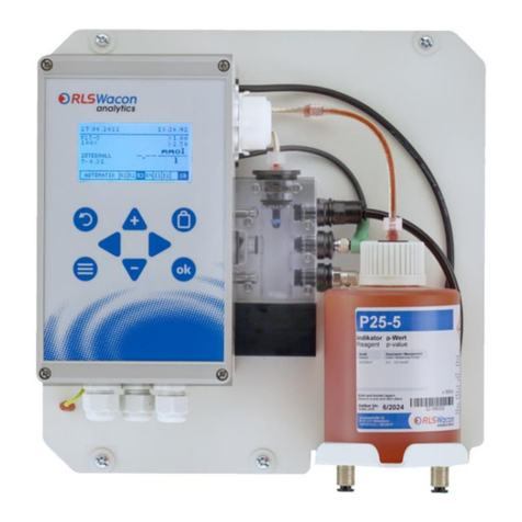
1. Wall-mounted analyzer
The analyzer consists of a controller and the measuring chamber. Both are mounted on a
wall bracket. This version is fully functional and includes connections for the water inlet and
-outlet and a holder for holding an reagent bottle (Figure 1).
Article name
Article no.
Analyzer SYCON 2702 with wall mounting
230 V version
30-010 162
Operating manual (English)
33-099 723

© RLS Wacon GmbH ∙ +49 (0)5121 28126 0 ∙ info@rls-wacon.de 7
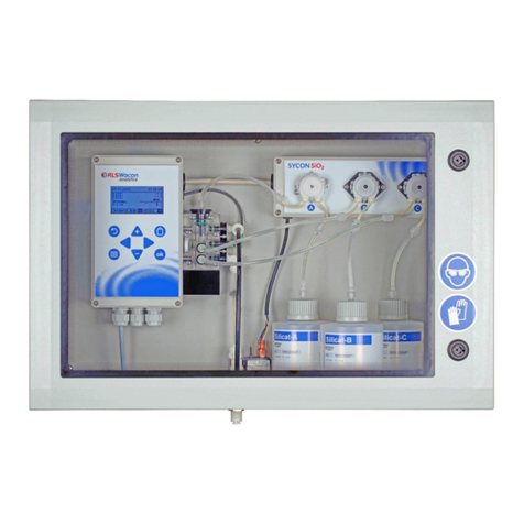
2. Analyzer in housing
Optionally for wall-mounted analyzer, a plastic housing is available in order to use the
analyzer in locations where more severe contamination is expected (Figure 2). The analyzer
on the wall mount can be quickly mounted in the housing with 4 screws. If the analyzer and
the housing are ordered together, the device is already mounted in the housing.
Article name
Article no.
Analyzer SYCON 2702 with wall mounting
230 V version
30-010 162
Operating manual (German)
33-099 722
Housing for SYCON 2702 including wall mounting straps
33-099 005
The analyzer can be operated intuitively via menu using the graphic display and 8 keys on the
controller housing.
Figure 1:
Wall mounted SYCON 2702
Figure 2:
Wall mounted SYCON 2702 in housing
The wall mounted SYCON 2702 analyzer is mounted in the housing with 4
supplied screws.
SYCON 2702 in detail

© RLS Wacon GmbH ∙ +49 (0)5121 28126 0 ∙ info@rls-wacon.de 8
Device description
The analyzer consists of the following components: The controller with graphic display and control
panel is on the left side of the device. 4 cable bushings are provided on the lower controller
housing. The dosing pump is on the right side and the measuring chamber is below the dosing
pump.
The dosing pump is plugged onto the motor shaft of the motor and snaps into the receptacle. It
can be removed without tools. The measuring chamber is attached to 2 guide pins on the
controller housing. This can also be removed without tools and is undone with 2 captive locking
pins. Dosing plugs, actuator plugs, inlet- and outlet plugs are attached to the measuring chamber
in the same way and can be quickly undone.
The measuring chamber, which is always depressurised and always filled to prevent germs, is in the
middle. The actuator plug with a white high-power LED is in the middle of the measuring chamber.
The sensor system is located in the housing. The agitator (magnetic agitator), which is firmly
connected to the housing, is below the measuring chamber.
The water connections for hoses with an outer diameter of 6 mm are below the reagent bottle.
Inlet with sample water (left) and outlet (right). Both are firmly bolted to the wall bracket.
There is a solenoid valve in the supply line behind the reagent bottle.
Figure: View of the solenoid valve (no reagent bottle installed)
For a more detailed description of the components, see page 30.
SYCON 2702 in detail

© RLS Wacon GmbH ∙ +49 (0)5121 28126 0 ∙ info@rls-wacon.de 9
Principle of function
The SYCON 2702 based on the SYCON series is an online analyzer for the automatic determination
of water parameters according to the colorimetric titration method. By adding an reagent to the
water sample, a colour reaction is produced. Depending on the reagent used, the device evaluates
the colour intensity. By changing the colour of the sample during the addition of the reagent, the
SYCON 2702 calculates the concentration of the substances in water. The device can only
determine one parameter at a time. Parameters and measuring range are determined by the
reagent used.
General specification
Parameter
Value/range
Voltage supply
(230 V version)
85 - 305 VAC (47...440 Hz)
Power consumption
25 VA (in operation)
3.5 VA (standby)
Load capacity
Load capacity of the relays with internal current supply of 1 A
from terminals 5 to 8
Load capacity of the relays with external current supply of 2.5 A
Protection class
open wall mounting IP43
Installation in the housing IP54
Storage temperature
0 °C –45 °C
Ambient temperature
10 °C –45 °C
Measuring water
temperature
5 °C –40 °C
Air humidity
20 –90 % RH (without ice or condensate)
Pressure of inlet water
min: 0.5 bar - max: 5 bar - recommendation 1 - 2 bar
General inlet water
clear, colourless, free of solids, without gas bubbles
Requirements for the water
quality when measuring the
water hardness
pH:
4 - 10
Iron:
< 3 ppm
Copper:
< 0.2 ppm
Aluminium:
< 0.1 ppm
Manganese:
< 0.2 ppm
Acid capacity:
KS 4.3 < 5 mmol/l
Note on oxidizing agents:
Oxidizing agents, e.g. calcium hypochlorite, chlorine, chlorine dioxide, sodium hypochlorite or
ozone beyond the limits permitted in "TrinkwV 2012" attack the dye contained in the reagent and
interfere with the measurement. An exact determination of the water hardness is no longer
guaranteed. An activated carbon filter upstream of the analyzer can remove these oxidants from
the sample water and thus allow the correct determination of the water hardness.
The capacity of an activated carbon filter consumes during operation. Therefore, the activated
carbon filter must be replaced at regular intervals. The effectiveness of the charcoal filter can be
checked using Caldur® test kits.
SYCON 2702 in detail

© RLS Wacon GmbH ∙ +49 (0)5121 28126 0 ∙ info@rls-wacon.de 10
SYCON 2702 in detail
Technical data
Parameter
Value/range
Installation
Wall mounting in closed rooms
Dimensions
without housing:
274 x 275 x 129 mm (W x H x D)
with housing:
332 x 345 x 190 mm (W x H x D)
Weight
without housing:
approx. 1.9 kg
with housing:
approx. 3.8 kg
Analysis properties
Parameter
Value/range
Measurement
method
Titration with colour change
Measurement
range
Total hardness
Carbonate hardness
°dH
0.012 …30
0.3 …22.5
°f
0.021 …53.6
0.5 …40.2
ppm CaCO3
0.21 …535.7
5.4 …401.8
mmol/l
0.0021 …5.36
0.11 … 8.04
°e
0.015 …38.6
0.39 …28.9
°Ж
0.0043 … 10.7
0.21 … 16.1
The measuring range is defined by the reagent used. The entire measuring
range of the total hardness is achieved by using different reagents. (The
following units are available for the analysis value: °dH, °f, ppm CaCO3,
mmol/l, °e, °Ж these are shown in the display).
Accuracy
Measuring accuracy: ± 5% of the maximum reading of the respectively used
reagent.
Repeat accuracy: ± 2.5% of the maximum reading of the reagent used
Please note: Depending on the substances in the water, there may be shifts
in the reading that affect the measurement accuracy. In such cases, we
recommend performing a hardness measurement by hand titration and
calibrating the analyzer to this reading.
Current interface
± 0.3 mA
Reagent
consumption
approx. 0.05 - 0.5 ml/analysis, depending on the measured water hardness
Measuring duration
approx. 3 min, depending on the water hardness and the set flushing time
Number of
analyses
max. approx. 10,000 analyses / 500 ml of reagent at low water hardness. The
consumption depends on the measured water hardness and the reagent
used.
Shelf life of the
reagents
at least 2 years with proper storage (<25° C, dark)
Water
consumption
approx. 1 l/analysis with 2 bar
The water consumption varies depending on the inlet pressure and the set
flushing time.

© RLS Wacon GmbH ∙ +49 (0)5121 28126 0 ∙ info@rls-wacon.de 11
Inputs/outputs
Parameter
Value/range
2 relay outputs
max. 250 VAC / VDC 1 A (For more information, see page 9)
as potential-free outputs NC/NO
The relays provide the following functions:
•Limit alarm
•Device error
•Standby
Signal input
electrically separated contact input
•Start analysis
•Flow switch
•Interval reset
Analogue output
0 –20 mA / 4 –20 mA
Resolution: < 100 μA
max. load: 750 Ω
Maintenance interval
Interval
Maintenance works
every 6 months
Cleaning of measurement chamber
At high ambient- and water temperatures or water with high organic
load, the cleaning intervals may need to be shortened.
every 30,000 analyses or
after 2 years of
operation
Cleaning of measurement chamber (as above),
Installation of maintenance kit: Changing the peristaltic pump
cartridge and the gaskets
SYCON 2702 in detail

© RLS Wacon GmbH ∙ +49 (0)5121 28126 0 ∙ info@rls-wacon.de 12
SYCON 2702 in detail
Reagents for monitoring total hardness
Name
Reagent
Measurement ranges
Art.-no.
500 ml bottle
Art.-no.
4 x 500 ml
bottles
°dH
ppm CaCO3
°f
H25-0,02
0.012 ... 0.12
0.21 ... 2.14
0.021 ... 0.214
32-084 115
32-484 115
H25-0,05
0.02 ... 0.2
0.36 ... 3.57
0.036 ... 0.357
32-084 125
32-484 125
H25-0,1
0.03 ... 0.3
0.54 ... 5.36
0.054 ... 0.536
32-084 135
32-484 135
H25-0,2
0.06 ... 0.6
1.1 ... 10.7
0.11 ... 1.07
32-084 145
32-484 145
H25-0,3
0.09 ... 0.9
1.6 ... 16.1
0.16 ... 1.61
32-084 155
32-484 155
H25-0,5
0.15 ... 1.5
2.7 ... 26.8
0.27 ... 2.68
32-084 165
32-484 165
H25-1
0.3 ... 3.0
5.4 ... 53.6
0.54 ... 5.36
32-084 175
32-484 175
H25-2
0.6 ... 6.0
10.7 ... 107.1
1.1 ... 10.7
32-084 185
32-484 185
H25-3
0.9 ... 9.0
16.1 ... 160.7
1.6 ... 16.1
32-084 195
32-484 195
H25-5
1.5 ... 15
26.8 ... 267.9
2.7 ... 26.8
32-084 205
32-484 205
H25-10
3 ... 30
53.6 ... 535.7
5.4 ... 53.6
32-084 215
32-484 215
(The following units are available for the analysis value: °dH, °f, ppm CaCO3, mmol/l, °e, °Ж these
are shown in the display).
Reagents for monitoring carbonate hardness
Name
Reagent
Measurement range
Art.-no.
500 ml bottle
Art.-no.
4 x 500 ml
bottles
°dH
mmol/l
°f
C25-1
0.3 ... 7.5
0.11 ... 2.68
0.5 ... 13.4
32-086 125
32-486 125
C25-1,5
0.5 ... 11.5
0.16 ... 4.11
0.8 ... 20.5
32-086 135
32-486 135
C25-2
0.6 ... 15.0
0.21 ... 5.36
1.1 ... 26.8
32-086 145
32-486 145
C25-3
0.9 ... 22.5
0.32 ... 8.04
1.6 ... 40.2
32-086 155
32-486 155
(The following units are available for the analysis value: °dH, °f, ppm CaCO3, mmol/l, °e, °Ж these
are shown in the display).
The measured value to be monitored should be as close to the middle of the
measuring range of the reagent as possible.
One bottle of reagent suffices for at least 10,000 analyses if the measurement point is in the lower
range of the reagent type used.
The exact number of possible analyses with an reagent bottle depends on the respective degree of
hardness and the reagent used.

© RLS Wacon GmbH ∙ +49 (0)5121 28126 0 ∙ info@rls-wacon.de 13
Installation
The installation should be done in the following steps to avoid errors:
•Install the analyzer in a dry, easily accessible and easily visible location.
•Fix the analyzer or housing stably with screws according to the manual.
•Connect the device electrically and pay attention to the correct input voltage. Ensure this
using the nameplate.
•Connect inlets and outlets according to the installation manual. Pay attention to a correct
inlet pressure and free, short outlet.
•Insert the reagent and connect it to the dosing pump. Make sure that the connecting hoses
are not twisted.
•Do not switch on the device until all preliminary works have been completed and the
housing is closed.
•Now set the device settings on the device.
The sample water must be clear and free of solids. Otherwise, a filter should
be provided in front of the analyzer. Solids in the water can damage the
solenoid valve or prevent it from closing. If the solenoid valve blocks or does
not open or close any longer, the measuring chamber will not be flown-
through properly. This leads to incorrect measurements.
Temperature of the sample water must be between 5 and 40 °C.
If the sample water has a higher temperature, a sample cooler should be
used. This is available as an accessory.

© RLS Wacon GmbH ∙ +49 (0)5121 28126 0 ∙ info@rls-wacon.de 14
Installation
Wall mounting without housing
The SYCON 2702 must be installed upright. The wall bracket has four 6 mm holes for attaching the
analyzer.
Figure: Drill guide for attaching the analyzer without housing
Position
Description
A
Cable glands for electrical connection
B
Water inlet connection for hose with 6 mm outer diameter
C
Water outlet connection for hose with 6 mm outer diameter

© RLS Wacon GmbH ∙ +49 (0)5121 28126 0 ∙ info@rls-wacon.de 15
Wall mounting with housing
The analyzer is optionally supplied with a matching housing. As accessories kit you will receive 4
mounting lugs with 6.5 mm holes, which are attached to the rear side of the housing.
To open the device, the available free space should be at least 450 x 350 mm (W x H).
Figure: Drill guide for attaching the analyzer in the housing
Position
Description
A
Cable glands for electrical connection
B
Water inlet connection for hose with 6 mm outer diameter
C
Water outlet connection for hose with 6 mm outer diameter
D
Door stop
E
Door locks
Installation

© RLS Wacon GmbH ∙ +49 (0)5121 28126 0 ∙ info@rls-wacon.de 16
Installation
The mounting lugs can be attached perpendicularly, as shown in the picture, or as rotated by 45° or
90°.
Figure: Rear view of the housing with vertically
mounted mounting lugs
Work on pressurised water lines
Pressure
Maintenance and repair works should only be carried out by qualified
personnel.
•Before starting work, make sure that all lines are depressurised.
•Hoses, connections and gaskets must be regularly checked and, if necessary, preventively
replaced, even if they show no visible damage. Maintenance intervals must be complied
with.
•Before commissioning after maintenance, make sure all connections, threaded fittings, and
gaskets are properly installed. Check that all housing parts are closed and filters or other
parts connected to the device are installed correctly.
•Remove all tools, spare parts or other materials required for maintenance prior to
commissioning.
•Clean the device, take any leaked fluids and leave the device in a clean condition.
•Check that all safety devices are present and ready for operation.

© RLS Wacon GmbH ∙ +49 (0)5121 28126 0 ∙ info@rls-wacon.de 17
The analyzer has 2 connections with bulkhead fittings for plastic hoses with
an external diameter of 6 mm for the water inlet (left) and water outlet
(right). These are only inserted into the screwed connections.
Figure: Connection of water inlet and -outlet
Pressure
The inlet pressure of the water sample must be between 0.5 and 5.0 bar.
The recommended inlet pressure of the water sample should be between 1
and 2 bar.
The hose length of the water outlet must not be longer than 2 m and must
lead away vertically downwards. The system must be able to relax freely
against the atmospheric pressure. There must be no back pressure greater
than the inlet pressure. The water is drained without pressure in an open
funnel or drain.
Operation with unpressurised sample water
If the sample water is depressurised, a pressure-controlled membrane or submersible pump is
required to transport the sample water into the measuring chamber of the analyzer.
Installation
Water inlet
Open funnel
Manual valve
(to be installed by customer)
Softening
Water outlet

© RLS Wacon GmbH ∙ +49 (0)5121 28126 0 ∙ info@rls-wacon.de 18
Electrical installation
Voltage
Work on electrical connections may only be carried out by authorised
specialist personnel in compliance with the current regulations. All lines must
be de-energised. The permissible supply voltage is 85 - 305 VAC (47 –440
Hz).
Open the lid of the controller by loosening the four screws in the corners of the lid.
Figure: Back cover of the lid (left side), circuit board (right side)
Position
Description
A
Wi-Fi (optional)
B
Battery holder
C
Solenoid valve port
D
Reagent pump port
E
Display port
F
Actuator plug LED port
G
Main switch port
H
2 x relay
I
RGB sensor
K
Agitator port
L
Fuse (5 x 20 mm ) 1 A time-lag
M
SD card base
N
Sound emitting device

© RLS Wacon GmbH ∙ +49 (0)5121 28126 0 ∙ info@rls-wacon.de 19
Connection of supply voltage
Figure: Terminals for the connection of the supply voltage (blue border)
Connection of supply voltage
Terminal designation
Description
1 PE
Earthing
2 PE
Earthing
3 L (power in)
Supply voltage between L and N 85 - 305 VAC (47 –440 Hz).
4 N (power in)
Output terminals which are connected via the device switch
Terminal designation
Description
5 L power out
Switched supply voltage
between L and N 85 - 305 VAC (47 –440 Hz).
6 L power out
7 N power out
8 N power out
Voltage
The maximum connected capacity of all loads must not exceed
250 VAC / 1 A.
Electrical installation

© RLS Wacon GmbH ∙ +49 (0)5121 28126 0 ∙ info@rls-wacon.de 20
Connection of the relay outputs
Figure: Terminals for connecting the relay outputs (blue border)
The relays are designed as change-over contacts, with a common connection and the switching
outputs NC and NO.
Output 1 water (relay 1): Water hardness notification
Terminal designation
Description
Connection
9 COM
Relay 1 COM common connection
see page 9
“Load capacity”
10 NC
Relay 1 NC normally closed
11 NO
Relay 1 NO normally open
Output 1 / relay 1 function (notification of water hardness):
If the measured value of the sample falls below the limit set in the SYCON, relay 1 is deenergised
and a connection from COM to NC is established. In addition, the symbol R1 is not marked in the
display.
If the measured value of the sample exceeds the limit set in the SYCON, relay 1 is energised and a
connection from COM to NO is established. In addition, the symbol R1 is highlighted in black on
the display.
Output 2 alarm (relay 2): Device error notification
Terminal designation
Description
Connection
12 COM
Relay 2 COM common connection
see page 9
“Load capacity”
13 NC
Relay 2 NC normally closed
14 NO
Relay 2 NO normally open
Output 2 / relay 2 function (device error notification):
If a device error occurs or the device is switched off, the relay 2 is deenergised (connection from
COM to NC). In addition, the symbol R2 is not marked in the display.
The relay 2 is energised in the error-free state of the device (connection from COM to NO), this
serves the wire break safety. In addition, the symbol R2 is highlighted in black on the display.
Electrical installation
Table of contents
Other RLS Wacon Measuring Instrument manuals
